
Abstract
The theoretical modeling, numerical simulation, and experimental verification for the impact dynamics of a flexible beam with large overall motion are researched. Based on the rigid-flexible coupling dynamic theory of flexible multibody system, the rigid-flexible coupling dynamic equations of the beam are established. On the use of the continuous contact force method (CCFM) and the contact constraint method (CCM), the respective global impact dynamic equations of the system are derived to achieve dynamic transformation and solution in different stages including impact and unimpact status. The experimental study on the impact dynamics of the flexible beam is investigated, and the dynamic response in the impact process is obtained. The experimental results are compared with the results of the impact dynamic simulation and the finite element method (FEM) simulation. The system's dynamic behaviors in the impact process are analyzed, and the accuracy of the two impact dynamic theories is verified.
1. Introduction
In engineering fields, there are a lot of noncontinuous dynamic problems between complex multibody systems represented by contact and impact, such as landing impact of an aeroplane and wheel/rail contact problem [1, 2]. The impact process will make a great effect on the system's dynamic behavior due to its short duration of time and strong intensity of force. Impact has become an important factor that cannot be ignored in system analysis and control, and it brings great difficulties for the dynamic modeling and numerical simulation of multibody systems [3, 4].
A reasonable dynamic modeling approach is the research foundation for the impact dynamics of flexible multibody systems. According to different assumptions on the impact process, the impact dynamic modeling methods for flexible multibody systems can be summarized as the following three types as discussed by [5, 6]: the impulse-momentum method (IMM), the continuous contact force method (CCFM), and the contact constraint method (CCM).
The impulse-momentum method is an approximate approach which is based on the classic impact theory for rigid bodies, and the impact is considered to finish instantaneously. The state of motion of the system after impact is acquired by calculating the generalized impulse-momentum equations and the coefficient of restitution equations, however, the dynamic responses in the impact process cannot be obtained [7, 8]. The continuous contact force method assumes that the impact force is caused by the local contact deformation, and it is an approximate method that replaces the complex deformation of the contact region by the contact force element. Researchers have made a series of studies on the impact dynamics of multibody systems by using different continuous contact force models [9–11]. The contact constraint method considers the contact effect as the contact constraints which are based on the kinematic conditions of the impact process. The kinematic variables of the system and the contact force are obtained by calculating the dynamic equations within the constraint equations. And the contact constraint method has also been widely used as discussed by [12–14].
Only limited experimental researches on the impact dynamics of flexible multibody systems can be found, because the impact process is a transient dynamic behavior with very short duration of time and it raises greater requirements for the response speed of the experimental instruments and the design of the experimental scheme. Seifried et al. [15] investigated the radial impact of a steel sphere impacting with a half-circular aluminum plate both numerically and experimentally, and Louge and Adams [16] observed oblique impacts of a hard aluminum oxide sphere on a thick elastoplastic polycarbonate plate by recording stroboscopic photographs of the sphere trajectory and spin.
In order to describe the global rigid-flexible coupling impact dynamic behaviors of a flexible beam with large overall motion accurately, the dynamics of the flexible beam impacting the fixed-rigid surface will be studied. The unimpact dynamic equations of the beam will be established by using the rigid-flexible coupling theory. The impact dynamic equations will be derived on the use of the continuous contact force model and the contact constraint model, respectively, and the characteristics of the two models will be analyzed. The experimental research of the impact dynamics of the flexible beam will be investigated. And the simulation results using the two impact models will be compared with the experimental results and the FEM results to verify the accuracy of the impact modeling methods.
2. Equations of Motion
The impact dynamics of a flexible cantilever beam rotating about joint O are studied, as shown in Figure 1. A point P on the beam impacts with a point Q on the rigid O-XZ plane. The beam is with the length L, Young's modulus E, the cross-sectional moment of inertia I, the cross-sectional area S, and the volume density ρ. The driving torque at the rotating joint is τ. An inertial coordinate system OXY is established over the shaft O of the flexible beam, with the base vectors
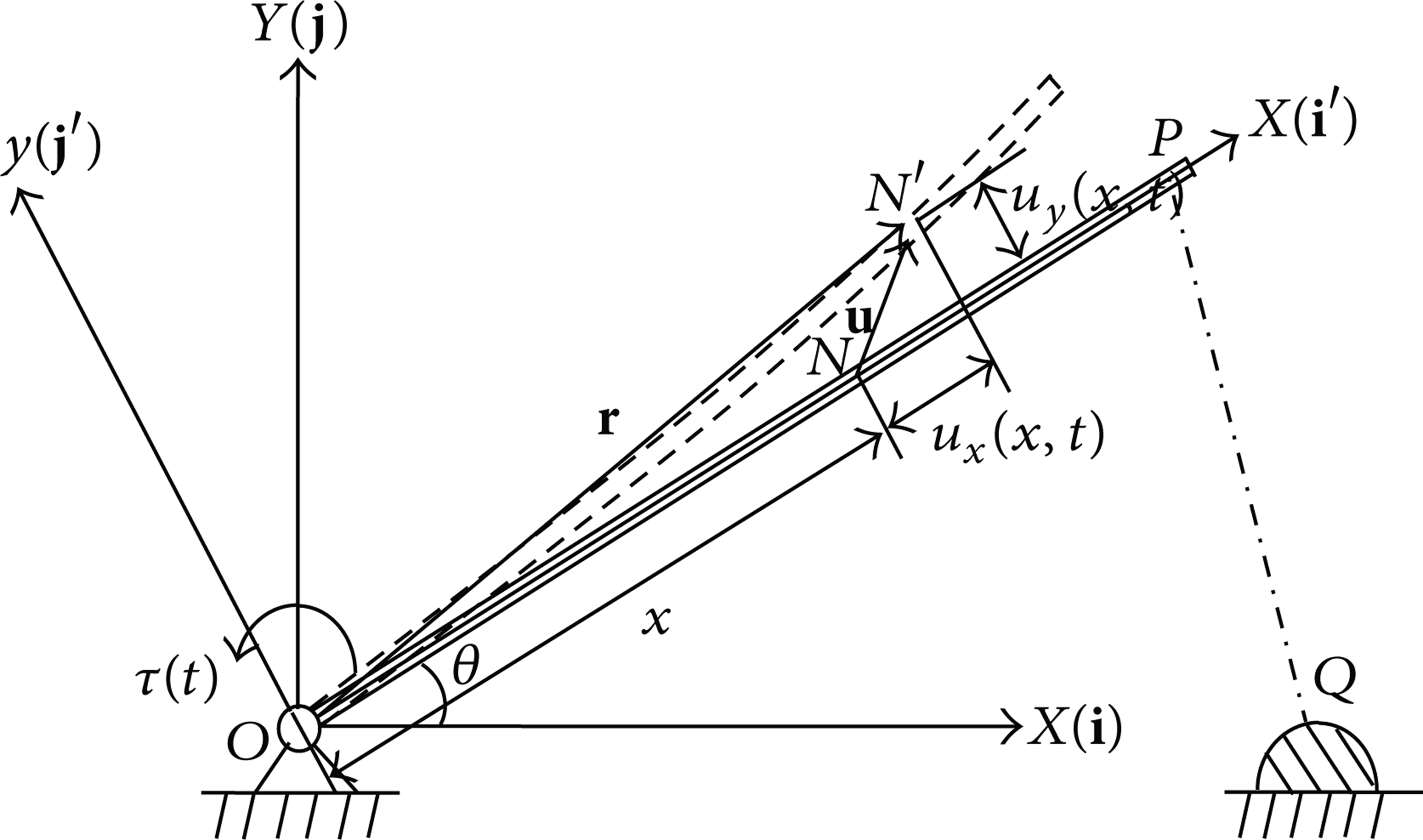
Flexible beam with large overall motion.
The flexible beam is assumed to be a slender Euler-Bernoulli beam. The description of the beam's deformation is shown in Figure 1. In the floating coordinate system, a point N(x, 0) on the beam when undeformed moves to N′(x′, y′), then, the vector of the relative deformation of N in the floating coordinate system is

The transverse bending deformation and the longitudinal shortening caused by transverse deformation which is also called the coupling deformation item are considered, while the axial tension and compression deformation are ignored. In (1),u y (x, t) is the transverse deformation and u x (x, t) is the coupling deformation of point N. The assumed mode method is used to describe the beam's deformation, and the deformation can be expressed as

In (2) and (3), Φ
y
(x) is the row vector of the transverse modal functions,
u x in (3) is the nonlinear second-order coupling item of the deformation [17], which is ignored in the traditional zeroth-order dynamic model. When the large overall motion is at high speed, the coupling deformation will have a significant effect on the system's dynamic behavior. By considering the coupling deformation item, the rigid-flexible coupling dynamic model mentioned here is a more accurate model.
The position vector of point N in the inertial coordinate system after deformation is

where
And the velocity vector of point N in the floating coordinate system is as follows:

Then, the energy status and the state of motion of the entire beam can be calculated. The kinetic energy T of the system is

And the potential energy V of the system can be expressed as

where V E is the elastic potential energy and V G is the gravitational potential energy, considered as the following:

In which
The system is holonomic and
After complex derivation, as discussed by [18], the unimpact rigid-flexible coupling dynamic equations of the system can be obtained as

where
3. Impact Dynamic Modeling
For the impact dynamics of a flexible beam with large overall motion, the large overall motion, the small deformation motion, the impact process, and the coupling effect of them need to be fully considered. The continuous contact force method and the contact constraint method are used, respectively, in the impact dynamic modeling of the system. For both methods, the corresponding impact solving part can be added to the unimpact dynamic equations of the system programmatically and conveniently. The following assumptions for the impact models are introduced: the impact is point-to-point impact, and the size and inertia of the local impacting area do not change during the impact process.
3.1. Continuous Contact Force Method (CCFM)
For CCFM, it is assumed that the small deformation of flexible bodies is within the range of linear elasticity, and the impact force is caused by the local contact deformation. The penetrating displacement and velocity between the impacting bodies are chosen as the calculating parameters for the impact force. It is an approximation method that replaces the complex deformation of the contact area with elastic or elastic-plastic force elements. The advantage of the continuous contact force method is that the impact force in the entire impact process can be calculated, and the conversion from unimpact process to impact process is continuous and smooth. Thus, the method is widely used in engineering fields, especially in elastic impact at low speed. However, the contact parameters of CCFM do not have a unified form and are difficult to obtain. The method is mostly based on the quasistatic contact theories, and the influence of the large overall motion and the stress wave is not considered. Meanwhile, the assumption that the impacting bodies penetrate into each other does not meet the physical reality.
In this paper, the nonlinear spring damper model is selected as the CCFM model. The elastic contact force is used to reflect the restoring force, and the nonlinear damping force is used to reflect the energy loss in the impact process, as shown in Figure 2. The elastic contact force is along with the normal direction of impact and is always a compression force. The direction of the nonlinear damping force is opposite to the direction of the relative velocity of the impacting bodies.

Nonlinear spring damper model.
The nonlinear spring damper model describes the contact-impact process based on the Hertz contact theory, and the nonlinear damping force is added artificially. The expression of the total normal impact force is
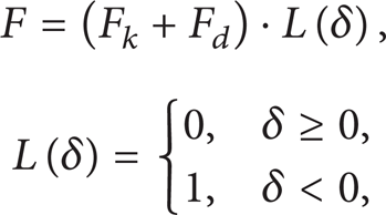
where δ is the penetrating capacity between the impacting bodies which is negative when the impacting bodies penetrate into each other, L(δ) is a logic function judging contact due to δ, F k is the normal elastic contact force, and F d is the nonlinear damping force. As discussed by [10], the concrete expressions are selected as follows:
In (12),
The concept of the impact force potential energy is introduced [19], and it is used to calculate the generalized force corresponding with the impact force. As a result, the influence of the impact force on the system's dynamics exists only on the generalized force item. Thus, the impact dynamic equations of the system are established by adding the generalized impact force item to the unimpact dynamic equations (10), while the original generalized mass matrix

In which,
The impact dynamic equations of the system can be established as follows:

In (14), the expressions of the generalized coordinate array

where
3.2. Contact Constraint Method (CCM)
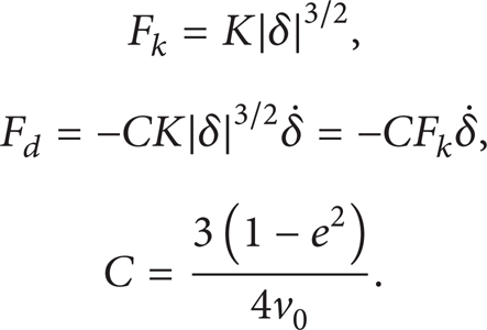
For CCM, contact-impact related constraint equations are added to the system's dynamic equations in the impact process to solve the impact dynamic problem, which means that the two impacting points P and Q on the two impacting bodies keep the same position in the impact process, as shown in Figure 3. Then the impact dynamics are solved by adding the unilateral contact constraint equations to the original unimpact dynamic equations, and the impact dynamic equations of the system turn from ordinary differential equations (ODEs) into differential algebraic equations (DAEs). The assumptions that the impact finishes instantaneously and the impacting bodies penetrate into each other are not needed for CCM. The essence of the method is that the contact constraints are imposed on the system according to the kinematic conditions of the impact process, and the impact force and the system's dynamic response are obtained by calculating the global dynamic equations rather than given artificially before impact. With respect to IMM which cannot calculate the impact force as well as CCFM which has difficulties in obtaining the contact parameters, the CCM has the advantages in that the entire impact process can be calculated and the contact-related parameters by adding artificially are not needed. However, the state of motion of the system mutates at the initial impact moment due to the fact that the system turns from unconstraint status into constraint status instantaneously. And it brings difficulties to the numerical calculation as a result of the jump and discontinuity phenomenon.

Contact constraint model.
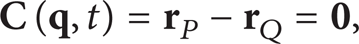
The system's degree of freedom is n and the number of contact constraint equations in the impact process is s. Then, the contact constraint equations in the form of position, velocity, and acceleration can be written as

In (16) to (18), the position constraint equation
The contact constraint equation in the acceleration form (18) can also be written as
Then, the impact dynamic equations of the system are

where
The numerical violation and calculation difficulty may occur at the initial impact moment due to the uncoordination of motion by adding contact constraints directly. Therefore, a method is needed to achieve kinematic conversion from unimpact status to impact status at the initial impact moment, to realize motion coordination and to get the initial impact conditions by adding contact constraints [14]. It is difficult to obtain the initial impact conditions, and scholars do not have a unified opinion on them by far. Some methods for obtaining the initial impact conditions have been reported, such as getting the mutated value of velocity according to the first-order discontinuity in an elastic continuum in the stress wave propagation of flexible bodies, and getting the coordination conditions of velocity using the local assumption in the substructure method.
The IMM is chosen to obtain the initial impact conditions in this paper. The IMM is used once on the system at the initial impact moment, and the coefficient of restitution e is set to be 0. Then, the initial impact conditions are obtained, and the kinematic conversion from unimpact status to impact status is achieved. After IMM is used, the impacting point P at the beam bonds to the impact surface naturally after the normal velocity mutates, and the conditions for adding contact constraints are met.
The impact dynamic equations of IMM are shown in [8] as follows:

where
At the initial impact moment, (21) is used once for calculation and e is set to be 0. Then, the kinematic conversion from unimpact status to impact status and the motion coordination are achieved without other assumptions. After the calculation, the generalized coordinates of the system do not change, and the generalized velocities of the system mutate at the moment. And the initial conditions for using CCM can be established as

4. Experimental Verification
The experiment that a flexible beam with large rotary motion impacts with a rigid hemisphere is carried out to verify the accuracy of the above two impact dynamic modeling theories.
The impact of flexible bodies is completed in a very short time; therefore, the response measurement on the impact process raises high requirements for the performance of the experimental platform and the accuracy of the measuring instruments. The experimental testing system of the impact of flexible multibody system consists of the test bench, laser vibrometer, quartz piezoelectric force sensor, conditioning amplifiers, calibrator of vibration sensor, electric power, Polytec Scanning Vibrometer (PSV) software system, and LABIVIEW processing software system. As shown in Figure 4, the laser vibrometer is used to acquire the velocity signal and the piezoelectric force sensor is used to acquire the force signal during impact. The beginning and ending of the impact is determined by the sign of the impact force. The experimental system does not need additional equipment, which reduces the interference in the experimental system. As shown in Figure 5, the test bench consists of the aluminum frame, flexible beam, cast iron base, sensors fixed standoffs, clamping devices, position-limit beam, auxiliary wires, and fixing equipment. The initial angle and the impact velocity of the beam are controlled by the position of the position-limit beam.
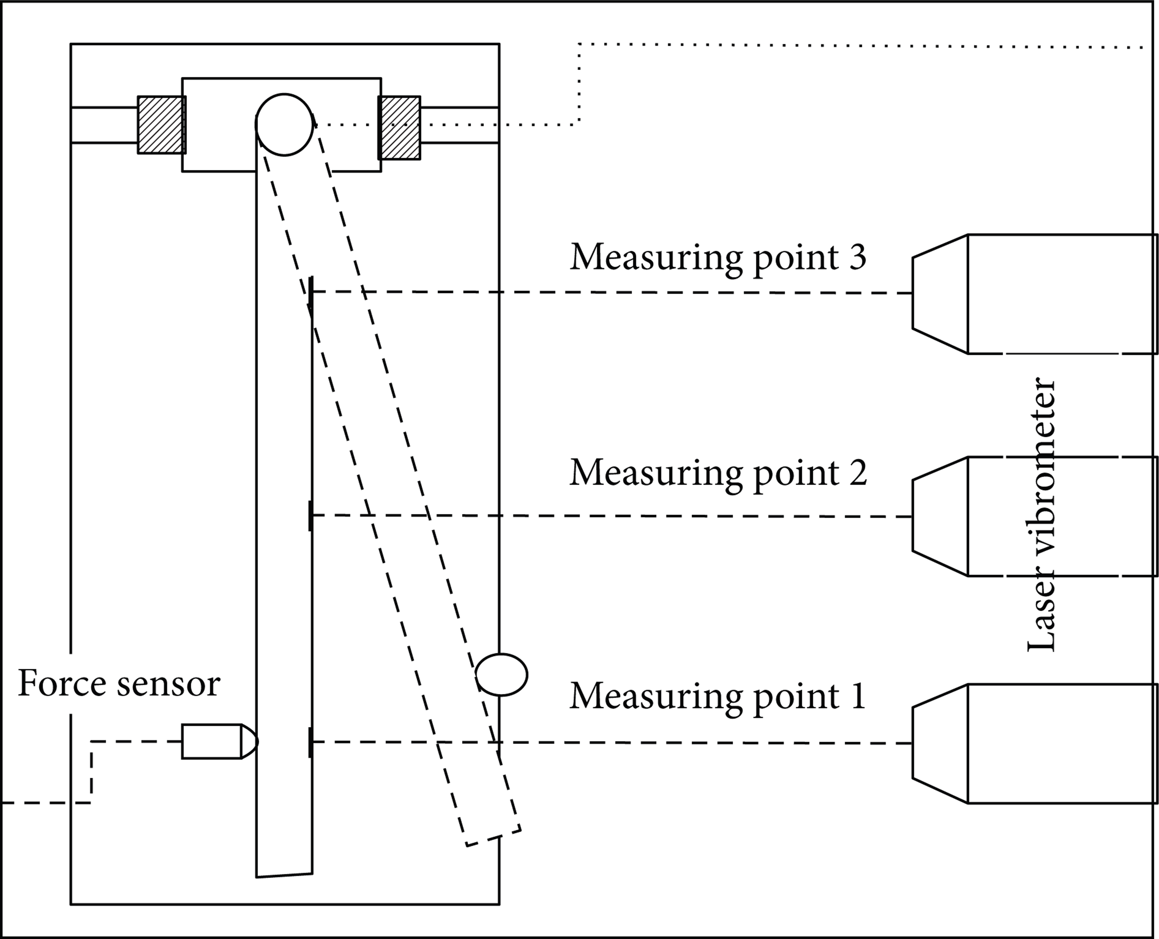
Experimental schematic diagram.
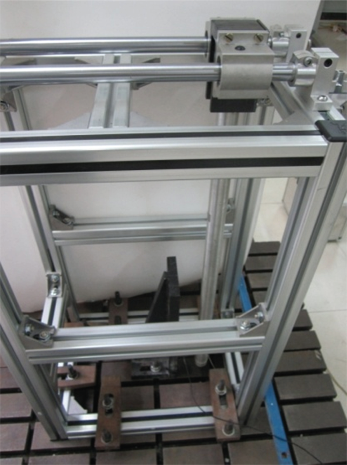
Test bench.
The experimental subject is a flexible beam with large rotary motion, and the free-fall flexible beam impacts with the aluminum hemisphere of the force sensor. The impact force response at the impacting position and the normal velocity response of three points on the beam are measured. The aluminum beam with cylinder cross-section has the length L = 0.7 m, cross-sectional radius R = 0.0145 m, area moment of inertia I = 3.47e – 8 m4, mass density ρ = 2767 kg/m3, Young's modulus E = 68.95 GPa, and Poisson's ratio μ = 0.3. The impacting position L p = 0.585 m and the normal velocity of the impacting point at the initial impact moment v0 = – 0.4 m/s.
5. Simulation and Results Comparison
The impact dynamic simulation of a flexible beam corresponding to the experiment is carried out by using CCFM and CCM, respectively. The simulation results are compared with the experimental results and the FEM results by LS-DYNA which is widely used on calculating transient dynamic problems such as impact, to verify the accuracy and credibility of the impact dynamic solving methods.
When the simulation time is set to be 0.1 s and the time step is set to be1.0 e – 6 s, the CPU solving time is 19.9 s by using CCFM and 22.4 s by using CCM. It is the larger number of dynamic equations of CCM and the longer calculating time for DAEs which lead to the longer solving time for CCM.
The impact force and the normal velocity of the impacting point which is the measuring point 1 in Figure 4, obtained by CCFM, experiment, and LS-DYNA are compared, as shown in Figures 6 and 7. As seen from Figure 6, the impact force calculated by CCFM is closer to the experimental result, and the changing trends of the impact force are basically identical. However, the impact force calculated by FEM has a larger difference with the experimental result. The impact force increases from 0 at the start of impact and reduces to 0 at the end of impact, and the entire impact process lasts for 0.6 ms approximately. The impact force has two peaks: the maximum peak is 689 N (CCFM) and 584 N (experiment), and the second peak is 524 N (CCFM) and 297 N (experiment). The error of the maximum peak of the impact force is about 17.98% for CCFM and experiment.

Comparison of impact force (CCFM).

Comparison of normal velocity (CCFM).
In Figure 7, the normal velocity response of the impacting point calculated by CCFM after impact has some difference with the experimental result, but the overall changing trend is basically identical. The normal velocity of the impacting point changes immediately at the start of impact, and it reduces to 0 then increases reversely. The flexible beam is at the maximum compression state when the impact force reaches its maximum and the normal velocity of the impacting point becomes 0, which agrees with the actual situation of CCFM.
The impact force and the normal velocity of the impacting point obtained by CCM, experiment, and LS-DYNA are compared, as shown in Figures 8 and 9. As seen from Figure 8, the impact force calculated by CCM is closer to the experimental result, and the changing trends of the impact force are basically identical. The maximum peak of the impact force is 625 N (CCM) and 584 N (experiment), and the error of the maximum peak is about 7.02% for CCM and experiment, which is smaller than the CCFM. However, the number of the peak of the impact force obtained by CCM is more than that of the experimental result. It means that the impact force changes more dramatically, and the impact duration of time is a little shorter for CCM.
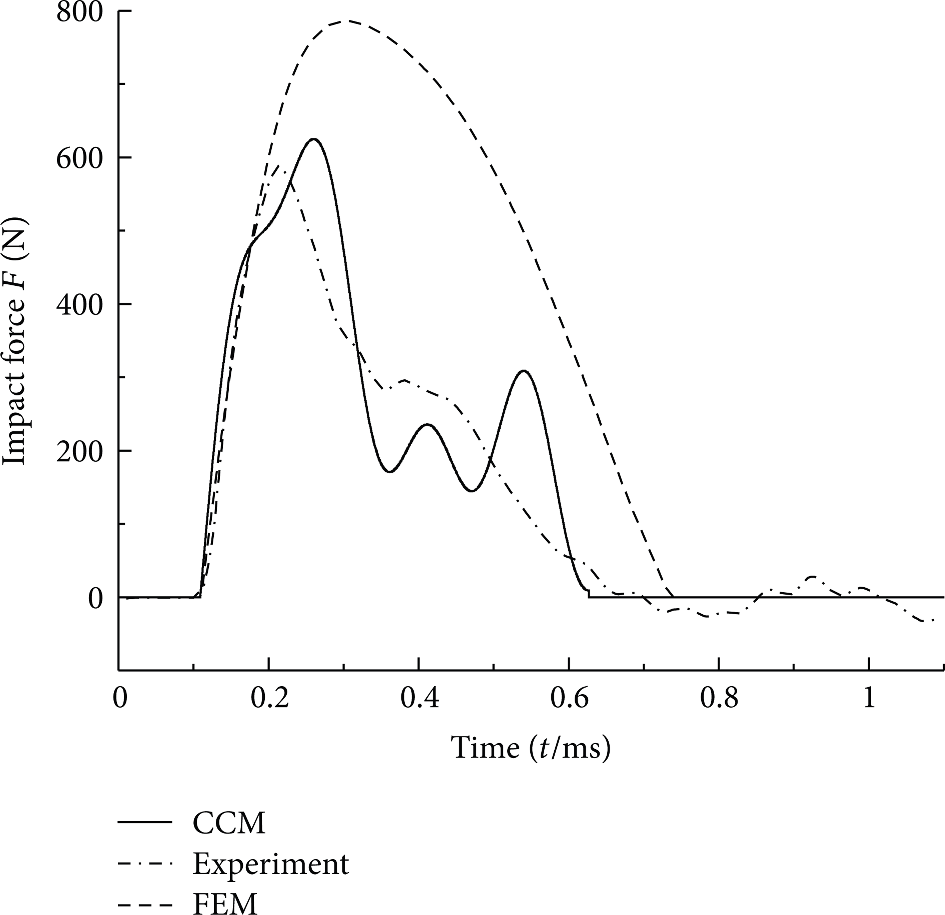
Comparison of impact force (CCM).

Comparison of normal velocity (CCM).
In Figure 9, the normal velocity response of the impacting point calculated by CCM after impact has some difference with the experimental result, but the overall changing trend is basically the same. The normal velocity of the impacting point mutates to 0 at the initial impact moment when establishing the initial impact conditions by using IMM, which agrees with the actual situation of CCM.
From Figures 6 to 9, it is known that CCFM and CCM are credible for solving the impact dynamics of flexible multibody system. The reasons which lead to the differences between numerical simulation and experimental results may include but not limited to that the force sensor is not an ideal rigid body and the damping influence is not considered. In the commercial FEM software, it is that the rigid-flexible coupling effect is ignored which makes an important role in the impact dynamics and there are some accuracy problems in the penalty function contact algorithm which leads to the huge difference of FEM.
6. Conclusion
In this paper, the theoretical modeling, numerical simulation, and experimental verification for the impact dynamics of a flexible beam with large overall motion are studied. Firstly, the effect of the coupling deformation on the dynamics of the system is considered, and the unimpact rigid-flexible coupling dynamic equations of the system are established. The CCFM based on the nonlinear spring damper model, and the CCM based on the impact kinematic constraints are selected to be the impact dynamic solving methods. The impact dynamic equations of the system are derived, respectively, and advantages and weaknesses of the two types of impact dynamic solving methods are analyzed. Based on the theoretical modeling, the impact experimental verification of the flexible beam is carried out and the simulation results are compared with the experimental results and the FEM simulation results. The variation of the dynamic behavior of the system is revealed during the impact process, and the accuracy and credibility of two impact dynamic solving methods are verified.
Footnotes
Acknowledgments
The paper is supported by the National Science Foundations of China (nos. 11132007, 11272155) and the 333 Project of Jiangsu Province (no. BRA2011172).