
Abstract
We suggest an enhanced approach for reliable bulk data transmission of image files, multimedia video files, and successive log files for monitoring systems over wireless sensor networks. Recently, some approaches have been proposed that use multiple blocks in a frame. These approaches simply drop the block that contains the error and the error-free blocks are transmitted to other nodes. This paper proposes an enhanced FEC scheme, called M-FEC, which reduces the overhead and the total number of transmissions. M-FEC fragments bulk data into many small blocks and these blocks are encoded using rateless codes. Only the erroneous blocks that are detected in a frame are dropped and a relay node waits for other incoming blocks in order to construct a full-sized frame. This simple approach can improve the performance of the FEC scheme over WSNs. Our experiments show that M-FEC reduces the number of received frames at the sink node by almost half compared to the previous approach. We compared our results for different degrees of Wi-Fi interference by choosing particular IEEE 802.15.4 channels and running our experiments for three different types of Wi-Fi interference.
1. Introduction
Wireless sensor nodes with real-time monitoring and multimedia capabilities can collect and transmit large images, videos, and successive log files from the environment to a sink [1–4]. Bulk data transmissions require reliable transmission from a source node to a sink node. The Automatic Repeat reQuest (ARQ) and Forward Error Correction (FEC) schemes are the most widely used error control techniques. The ARQ error recovery scheme requires retransmissions that increase cost and overhead even if improved retransmission algorithms are adapted. Two types of FEC (bit-level and packet-level FEC) have been proposed to guarantee reliability. While the bit-level FEC recovers from bit errors within a frame by including redundancy within each frame, the packet-level FEC recovers from packet loss through the use of redundancy packets.
In the bit-level FEC method, a proper amount of redundancy has to be added because excessive redundancy wastes resources over a good quality channel and insufficient redundancy does not allow for recovery from errors over a low-quality channel. Owing to the unpredictable changes in wireless channel quality, it is very difficult to gauge the FEC encoding redundancy to match the current channel error rate. In the packet-level FEC method, the sender takes the original contents (i.e., the original symbols) as input, generates the encoded symbols, and then transmits the original and encoded symbols to the receiver. The original and encoded symbols are treated equally in terms of the decoding process. The receiver does not have to receive all of the symbols. Instead, it only needs any k number of symbols to perform the decoding process, where k is the number of original symbols. Thus, the lost packets do not need to be retransmitted.
The Data Link Layer (DLL) usually deals with the trade-off between maximum channel utilization and effective error recovery. Given the frame overhead, such as frame headers, larger frame sizes are preferred in order to achieve high utilization. Smaller frame sizes are desirable for reducing the Frame Error Rate (FER) for a given Bit Error Rate (BER). It is very difficult to decide the appropriate frame size for a dramatically fluctuating wireless channel due to the conflict between high utilization and low FER that is described above. Multiple-blocks-in-a-frame approaches have been proposed to solve the dilemma above [5, 6]. These techniques package multiple blocks into a frame and the receiver checks whether there is an error block in the frame. In Seda [5], only error blocks are retransmitted to the receiver, rather than the whole frame. In the REFC method in [6], only blocks with errors are dropped. The other error-free blocks are transmitted to the next node. The receiver does not have to receive the dropped error block because reliability is guaranteed by packet-level FEC. The receiver can perform the decoding process after receiving any k number of blocks, where k is the number of original symbols. Seda [5] investigated the proper block size for optimal throughput under various channel conditions. The REFC method in [6] measures the channel utilization with four different block sizes. A TinyOS wireless sensor node can maximize a transmitting frame size up to 127 bytes, including 20 bytes for the header and 107 bytes of payload through CC2420 radio per transmission. Based on previous studies, it appears that 20–25 bytes is the ideal size for a block and four blocks can be packaged into a frame to be transmitted to neighboring nodes.
In this paper, we propose an enhanced multiple-block, packet-level type of FEC that is optimized for high channel utilization, low traffic load, and low overhead. Our approach, which is called M-FEC, inherits the multiple blocks in a frame scheme from REFC to resolve the trade-off between high utilization and efficient error recovery. By using packet-level FEC, such as Luby Transform (LT) codes [2], the sink and relay nodes do not have to worry about the dropped blocks since the sink needs additional blocks to decode and recover the original contents.
In contrast to REFC, M-FEC determines the transmission frame size to minimize the total number of frame transmissions. In REFC, the number of blocks in a frame is dependent on the number of error blocks. If there are no block errors, then REFC transmits four blocks in a frame. If block errors exist, then the number of blocks in the frame will be less than four because error blocks are dropped. The number of blocks in a frame will decrease as the frame travels through multiple paths to the sink. Only one block of a frame could be sent along the paths to the sink, but this transmission is not efficient due to high per-frame overhead, such as the frame header.
Our approach tries to transmit frames using the maximum available frame size. In M-FEC, if there is an error in a frame, only the block that contains the error is dropped, just as it is in REFC. However, this frame is not sent immediately to the next node. Instead, it is buffered until the current frame fills up to the full frame size. Thus, M-FEC reduces the number of transmissions and also maintains reliability for bulk data transmission applications, such as transmissions of large-size images, videos, and successive log files. Even though our approach is simple, it can cut the total number of transmissions in half, as compared to REFC, in a typical environment.
The rest of this paper is organized as follows. In Section 2, we describe efficient and reliable data transmission and error-correction methods for WSNs from related studies. In Section 3, we describe our proposed reliable block transmission method, M-FEC, in more detail and compare it to the original FEC system architecture. The M-FEC method increases the energy efficiency of wireless sensor nodes and decreases network traffic loads and overhead. In Section 4, we present various experiments using TinyOS Simulator (TOSSIM) [7] and a real testbed with 20 UBee430 wireless sensor motes that include ubiquitous sensor network RF modules with CC2420 radio chips and MSP430 microcontrollers. Experimental results show that the performance of the M-FEC method is better than the original FEC block transmission method in situations where there are higher BERs and Wi-Fi interference. We also show that the M-FEC method is more efficient than typical ARQ methods.
2. Related Works
Deployments of wireless networks are increasing rapidly. Interference from WSNs that are deployed in overlapping areas and unstable BERs are becoming a major problem for applications that require complete reliability. Many studies have focused on reliable transport protocols and optimization for packet error control in wireless networks. In this section, we describe reliable protocols that use the ARQ or FEC scheme.
However, these previous approaches face problems when they are used in WSNs. Reliable transport protocols are not efficient when the quality of wireless links is changing in real time. FEC schemes are often used in WSNs in order to improve error resiliency and lower transmission costs as compared to ARQ schemes.
2.1. Reliable/Congestion Transport Protocols
Related previous studies on reliable transport protocols are found in [8–13]. The Pump Slowly Fetch Quickly (PSFQ) method was proposed in [12]. It uses a hop-by-hop error recovery method, based on Negative ACKnowledgement (NACK), for reliable transport protocol. Source nodes inject messages, and relay nodes buffer and transmit the messages using three kinds of functions (pump, fetch, and report operation). Congestion control is required when the occurrence of NACKs rises because of lost packets. One of the congestion control methods for WSNs is COngestion Detection and Avoidance (CODA) [13], which includes an open loop hop-by-hop backpressure mechanism and a closed-loop multisource regulation mechanism. The CODA protocol first estimates network congestion by comparing the current throughput at intermediate nodes with the maximum throughput threshold for Carrier Sense Multiple Access (CSMA). Secondly, a sink controls the source using a closed-loop mechanism. However, there is still an issue with high energy consumption for channel loading with mathematical modeling. The Event-To-Sink Reliable Transport (ESRT) protocol [8] is another transport protocol that is used for congestion control. It assumes that every node has the same reporting rate and also has a problem with excessive energy consumption. ESRT monitors the local buffer level of sensor nodes and sets a congestion notification bit in the packets it forwards to sinks if the buffer overflows. If a sink receives a packet with the congestion notification bit set it infers congestion and broadcasts a control signal informing all source nodes to reduce their common reporting frequency according to some function.
2.2. Erasure-Resilient Codes
Erasure-resilient codes are closely related to error-correcting codes, which provide resilience to bit errors. On the other hand, erasure-resilient codes also provide resilience to packet-level losses. FEC is often used, rather than ARQ, for error recovery from high Bit Error Rates on asynchronous wireless channels, because high Frame Error Rates (FERs) can cause large delays for frames in ARQ-based data transmissions. Thus, we use the family of erasure-resilient codes related to error correcting codes.
2.2.1. Traditional (Basic) Block Codes
Reed-Solomon and Tornado codes are typical block codes with a fixed rate for reliable data distribution applications. In these codes, k input symbols are used to generate limited redundant symbols for a total of n encoding symbols. The values of k and n should be small and fixed before the encoding process starts.
The FEC encoder generates a sequence of encoding symbols
2.2.2. Rateless Codes
Rateless codes can overcome the limitation of encoding symbols and generate potentially unbounded numbers of encoding symbols from the FEC encoder. Luby et al. [14] described a particular class of foundation codes, called LT codes, which optimize the degree of distribution and guarantee the lowest overheads. There is another rateless code [15] that has a strong probability of correction encoding and decoding symbols. Unlike traditional block codes, rateless codes do not consider which encoding symbols have to be retransmitted to the receiver. The sender additionally transmits the required number of new encoding symbols from the receiver, and both of these rateless codes strongly guarantee probabilistic decoding along with low decoding overheads. Therefore, we apply rateless codes for M-FEC implementation.
3. System Architecture of M-FEC versus REFC
In this section, we discuss the system architecture, message format, and method for enhancing the multiple-block FEC scheme by reducing the total number of the frame transmissions. Fundamentally, M-FEC, in conjunction with REFC, is designed to recover from packet transmission errors on wireless links with low channel quality. M-FEC operates the same way as REFC at the source nodes and the sink nodes. However, at the relay nodes, M-FEC operates differently from REFC when it detects an error block in a frame.
3.1. Overview
We now briefly describe our FEC system architecture. FEC codes are employed to ensure reliable delivery in situations where there are unpredictable link loss rates. Compared with ARQ-based error control, FEC has the potential to decrease transmission overheads.
We use a block transmission method with FEC, so erroneous blocks do not have to be retransmitted. Only the error-free blocks in the frames will be transmitted. First, assume that a source node generates and transmits a frame toward a destination via relay nodes.
Figure 1 shows how operations proceed when a relay node receives a frame that includes error blocks in REFC. We will compare the M-FEC protocol to the FEC protocol in the following sections.
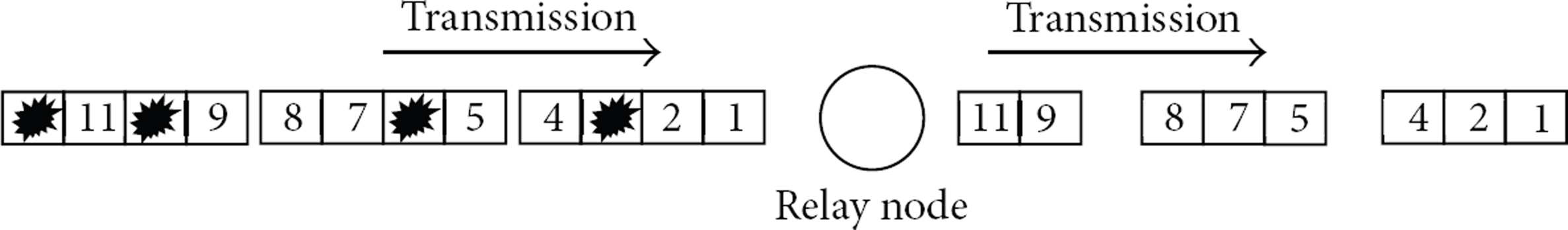
REFC block transmission protocol.
3.1.1. REFC Steps at the Relay Node
The relay node checks for erroneous blocks in a received frame. If no erroneous block is detected, the relay node transmits the received frame to the neighboring node. If an erroneous block is detected, then the relay node transmits a frame that does not include the erroneous blocks. (Erroneous blocks are simply dropped.) Thus, a transmission frame may include only one, two, or three blocks.
3.1.2. M-FEC Steps at the Relay Node
The relay node checks for erroneous blocks in a received frame. If no erroneous block is detected, the relay node transmits the received frame to the neighboring node. If an erroneous block is detected, then M-FEC does not transmit the frame to the neighboring node immediately. Instead, it waits until the next incoming blocks are available in order to fill the four blocks of frame that is about to be sent. The relay maintains a buffer for storing the remaining blocks after filling the previous frame.
The key idea of M-FEC is to reassemble the error-free blocks into full-sized frames at the relay nodes. Thus, four error-free blocks will be always included in a frame when a relay node tries to transmit.
In Figure 2, the M-FEC transmission protocol flows are depicted for three kinds of nodes. The source node, using erasure-resilient code, divides the contents into k blocks and generates n output symbols for packaging four blocks into a frame. The intermediate (relay) nodes check the blocks in a received frame in the next step of the data transmission. Finally, the sink node checks the blocks in a received frame to decode n blocks and reassemble the blocks. If the sink node receives enough blocks for the decoding process, it will reassemble the original data contents after the decoding process.

FEC communication protocol flows for source node, intermediate (relay) node, and sink node.
3.2. Basic FEC Message Format
Table 1 depicts the basic frame format proposed in REFC [6]. The original file is divided into k blocks, and then n blocks are generated from them through a channel encoder. Each block includes a block sequence number, block data, and 1 byte for the Cyclic Redundancy Check (CRC-8) data for error checking. If the block size is about 20–25 bytes, a transmission frame can have a maximum frame size with four blocks for optimal channel utilization. The number of blocks and the size of the blocks are optimized for high channel utilization [6]. The Media Access Control (MAC) layer for data transmission will receive a frame from the upper layer where blocks are packaged into a frame. We assume that sources transmit data to destination sink nodes via intermediate nodes that relay the data. An intermediate (relay) node will simply drop a block if an error is detected; only error-free blocks from the buffer are transmitted after being packaged into a frame.
FEC message formats for block transmission.

4. Experiments
For our experiments, we used two kinds of topologies. Figures 3 and 4 represent the basic structure of a single topology and a tree topology that were used for our experimental evaluation. Intermediate nodes include one or more relay nodes that deliver data to neighbors in the direction of the sink.

Single topology.
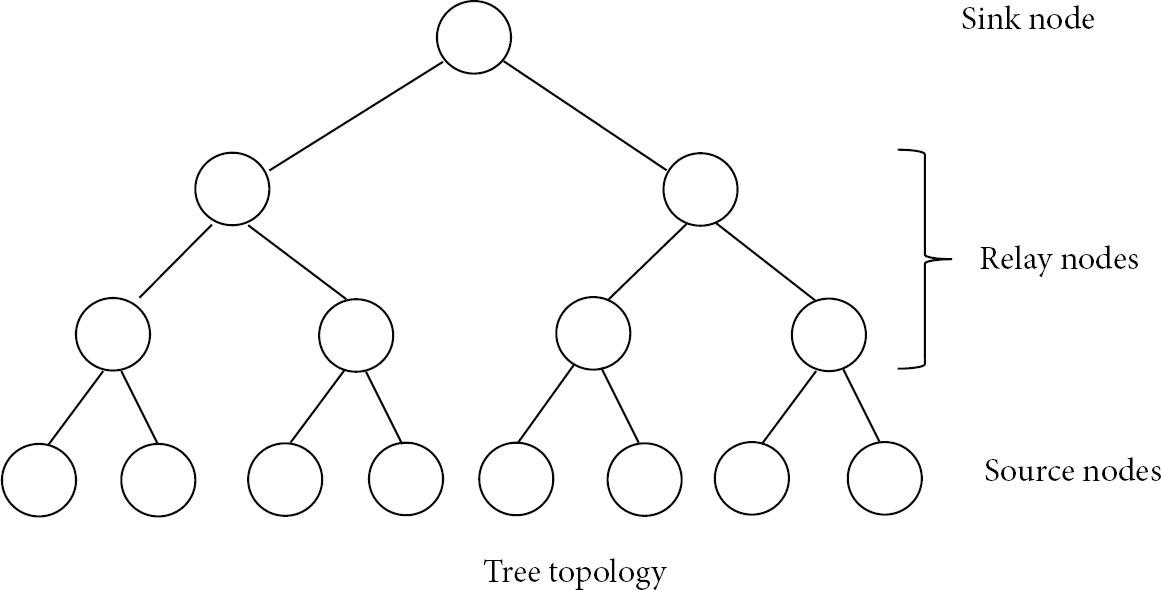
Basic topology models for experiments.
We implemented and ran ARQ, REFC, and M-FEC on TinyOS. TinyOS motes consist of three kinds of nodes: sink, relay, and source. We ran experiments using two schemes simultaneously at a given time. The combinations that we used were (a) REFC and M-FEC and (b) ARQ and M-FEC. The experiments used XubunTOS 2.0, which combines the Ubuntu and TinyOS operating systems. Additionally, all TinyOS-2.x motes in the outdoor experiments were operated at a height of 1 foot from the ground.
4.1. TinyOS-2.x Node
We used TinyOS UBee430 motes. These motes include Chipcon SmartRF CC2420 wireless transceivers, Texas Instruments MSP430 ultra-low power, Reduced Instruction Set Computing (RISC) mixed-signal microprocessor microcontrollers, 48 Kb of internal flash memory, and 10 Kb of internal random access memory (RAM). The Chipcon SmartRF CC2420 wireless transceiver is a 2.4 GHz, IEEE 802.15.4 compliant RF transceiver that is designed for low-power and low-voltage wireless applications. It has an effective data rate of 250 kbps.
4.2. Performance Evaluation
As shown in Figure 5, we measured the success/fail ratio for one hop of FEC data transmission based on a single-type topology for the TinyOS simulator (TOSSIM). A parameter space in TOSSIM is not a physical distance but rather a virtual distance between nodes. Large space values lead to high rates of transmission errors. The source node generates data frames every 250 ms in Figures 5 and 6. Many of the received blocks may be influenced by background noise or multipath fading of wireless signals.

One-hop data transmission success/fail ratio.

Comparison of the total number of received frames (TOSSIM, three-hop).
We controlled the channel error rate artificially using space in a TinyOS-1.x TOSSIM to develop various wireless channel environments. Figure 5 represents the frame error rate based on the space parameter.
In Figure 6, we compared the total number of received frames between REFC and M-FEC at the sink node. The simulation experiments were stopped if the receiver received the predetermined number of blocks. In REFC, the relay node transmits a received frame to its neighbor node even if there is only one error-free block in the received frame. In M-FEC, the relay node does not transmit a frame to the neighbor immediately. It waits until four blocks are accumulated into a frame. Thus, the number of frame transmissions will certainly be reduced by M-FEC. For a space value of 9, M-FEC reduces the number of received frames at the sink node by almost half. The lower the number of transmissions is, the lower the overhead for a given frame transmission method will be, as long as the same level of reliability is maintained.
We conducted an indoor experiment with four hops and a 250 ms frame interval. Figure 7 depicts the Frame Error Ratio (FER) and the total number of received frames based on the number of blocks in the frame. The number of received frames was measured for the four types of frames using four-hop transmissions over a single multihop path until the sink node received the predetermined numbers of blocks. The FER is defined here as the ratio of the number of nonreceived frames to the number of frames that were sent. We see that the average FER is about 25%. Among the received frames, the percentage of frames that contain four blocks is about 67% and the percentage of frames with three or fewer blocks is about 33%. This number increases as the level of channel errors and the number of hops increase.

FER and the total number of received frame using four-hop frame transmission.
We compared the number of frame transmissions between REFC and M-FEC for various channel error rates and transmission speeds in Figure 8 and we varied the frame transmission interval (1024, 768, 512, and 256 ms). For this simulation, experiments were marked as completed if the sink nodes received the predetermined numbers of blocks. Figure 8 shows that the difference between REFC and M-FEC for the number of frame transmissions increases as the channel error and transmission rate increase.

Comparison of the total number of frame transmissions (TOSSIM).
4.2.1. Wi-Fi Interference
Wireless local area networks, often referred to as Wi-Fi, can interfere with IEEE 802.15.4 networks, and the interference can cause critical performance degradation in WSNs. Because most of the IEEE 802.15.4 channels overlap with Wi-Fi network channels, data transmission can be affected [16]. Thus, we investigated how many Wi-Fi channels were being used while we were performing our experiments. Most Wi-Fi channel users were using channel 1, 6, or 11. Therefore, we were able to compare our results for different degrees of interference by choosing particular IEEE 802.15.4 channels and running our experiments for three different types of interference. We next describe throughput at the sink when M-FEC transmissions are influenced by Wi-Fi interference. Figure 9 shows how these wireless networks interfere with each other.
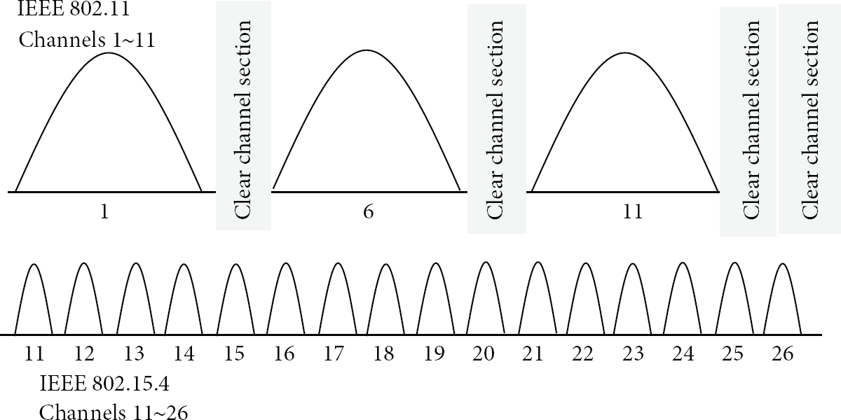
Channel interference between IEEE 802.15.4 and Wi-Fi.
We calculated the throughput (defined in (1)) in each of the following three cases with the same topology as seen in Figure 3.
Consider the following:
Noninterference case: nodes use a clear channel (e.g., 26) in order to avoid Wi-Fi interference. There are no overlaps between Wi-Fi channels and IEEE 802.15.4 channels 25 and 26. We continue to check Wi-Fi channels during the experiment in order to keep track of the number of Wi-Fi users. Normal interference case: the sensor nodes use IEEE 802.15.4 channel 11, which overlaps with Wi-Fi channel 1. Therefore, transmissions can be disturbed by a medium level of interference. Strong interference case: the sensor nodes use IEEE 802.15.4 channel 22, which overlaps heavily with Wi-Fi channel 11. This can cause many erroneous blocks to occur during the experiment.
The results from the three cases for Wi-Fi interference are shown in Figures 10, 11, and 12. The source node generates a frame every 250 ms and these generated frames are sent via relay nodes using multihop paths. The distance between nodes is about a half meter in Figure 10 and we also apply the same distance in Figures 11 and 12. We first confirmed that both M-FEC and REFC showed similar performances in Figure 10. The average throughput and the number of received frames were almost the same for both REFC and M-FEC because erroneous blocks were rarely detected. Second, we attempted an experiment for the normal interference case. The result for average throughput was similar to the noninterference case. However, the total number of received frames decreased by 10% as compared to the noninterference case. Third, we conducted another experiment for the strong interference case. We selected IEEE 802.15.4 channel 22, which overlaps with Wi-Fi channels from 9 to 12, in order to introduce strong interference with the data transmissions. In cases where many erroneous blocks occurred, the transmission overhead increased more for REFC than it did for M-FEC, because the erroneous blocks caused many non-full-sized frames in REFC. The difference in the total number of received frames between REFC and M-FEC was larger than in the previous two interference cases. Moreover, we found that transmission frame loss occurred more commonly in the strong interference case. As a result, in this case, the average throughput for RFEC was higher than the average throughput for M-FEC, because the packet losses for full-sized frames in M-FEC would degrade the throughput more than the packet losses for non-full-sized frames in REFC.

Noninterference case.

Normal interference case.
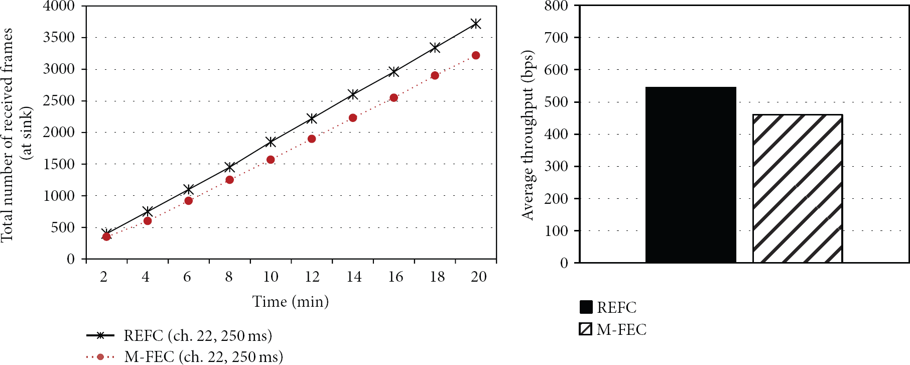
Strong interference case.
4.2.2. Overhead per Hop (Overall Network)
In REFC, non-full-sized frame transmission clearly causes additional overhead, such as MAC header data and metadata on TinyOS, when a receiver detects error blocks and immediately retransmits the frame after dropping the blocks that contain the errors. The sizes of the frames in REFC shrink as the frames are transmitted toward the sink due to the wireless channel errors.
We measured the overhead for each hop. The same number of transmitted frames, which include healthy frames with four blocks in both REFC and M-FEC, was not considered when we calculated the overhead values. We defined REFC and M-FEC overhead using

Figures 13 and 14 show additional overhead experiments. First, we performed an experiment for overhead using five hops with a single topology in Figure 13(a). The average overhead for REFC was about 2.2. The average overhead for M-FEC, on the other hand, was 1.45, as shown in Figure 13(b).

(a) Experiment for a single topology. (b) Overhead in accordance with error in each hop (left) at a relay node and average overhead (right).

(a) Experiment for a tree topology. (b) Overhead based on errors in each hop (left) at a relay node and average overhead (right).
We used tree topology in Figure 14(a) to consider more dynamic network environments. The topology includes five sources, which generate data every 250 ms, relay nodes, and the sink as a base station. The total average overhead for REFC was about 27% higher than for M-FEC, as shown in Figure 14(b).
In Figure 15, we experimented with a single topology again. However, the number of hops to the sink was increased. The average overhead for REFC average overhead was about 45% higher than it was for M-FEC.
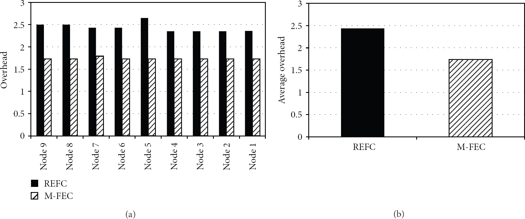
Overhead based on errors in each hop (a) at a relay node and average overhead (b).
4.2.3. Buffering Overhead (REFC versus M-FEC)
In M-FEC, each relay node has to buffer the frame until the next frame comes up to reorganize the full size of frame. This buffering and waiting the frame may increase the time for a node to receive all required blocks. We consider the increase of completion time as delay overhead and we measured the time to receive a certain number of blocks. We used the single topology with six hops in normal Wi-Fi interference. The source transmits the frame every 1 second.
Figure 16 shows the difference between the completion time of M-FEC and REFC. The cumulative block error rate at the sink node is 44% in M-FEC and 43% in REFC. While there is a buffering overhead in M-FEC, the delay overhead in M-FEC is not considerable. We have conducted many indoor experiments with normal Wi-Fi interference and the results are very similar. We also conducted the experiment in strong Wi-Fi interference and the completion time for M-FEC is 10% longer than REFC completion time. We consider the strong Wi-Fi interference case as the worst cast for the delay overhead. As we mentioned earlier, the frame loss is more common than block error in strong Wi-Fi interference. The packet losses for full-sized frames in M-FEC would increase the completion time more than the packet losses for non-full-sized frames in REFC.

Completion time to receive a certain number of blocks.
In TCP, queuing delay is crucial to the performance since TCP's performance is controlled by self-clocking. Queuing delay will increase the delay of ACK reception and this will affect the transmission rate. Both REFC and M-FEC's target application is a reliable bulk data transmission in WSN and their design goal is to provide the protocol which maximizes the usage of partially received bits and reduces the number of transmissions. While the small number of frame transmissions will reduce the network congestion, REFC and M-FEC did not consider the transmission rate control for the congestion yet. Since M-FEC uses constant bit rate for transmitting the frame and it does not use self-clocking, the delay at relay node for reorganize does not degrade the performance considerably. In our future work, we would like to propose the reliable congestion control using multiblock FEC.
5. Conclusions
Transmission errors occur dynamically in Wireless Sensor Networks based on varying environmental factors. Thus, an efficient reliability scheme is needed for WSNs in order to support bulk data transmission applications that require 100% reliability. In this paper, we proposed an enhanced FEC scheme that reduces the total number of frame transmissions. M-FEC uses multiple blocks in a frame and it reassembles error-free blocks in order to construct a full-sized frame. This multiple-block scheme makes it possible to achieve high utilization and to reduce transmission overhead at the same time. When the relay node detects an error in a received frame, it drops the blocks that contain the error and buffers the error-free blocks instead of transmitting the frame immediately to the next node. We showed that our M-FEC method reduces both traffic load and transmission overhead and also extends network lifetime. We performed extensive experiments for various network conditions and showed that M-FEC consumes fewer resources than REFC and ARQ in large WSNs. We found that M-FEC reduced transmission overhead by about 40% as compared to REFC.
Footnotes
Conflict of Interests
The author do not have a direct financial relation with the commercial identities mentioned in the paper.
Acknowledgment
This work was supported by Inha University, Republic of Korea.