
Abstract
The fatigue tests were carried out on door frame containing single-side design and double-side design to assess the effect of different designs on fatigue life. By contrast, the finite element method (FEM) was also used to analyze the stress distribution of the two frames. At last, the fracture morphologies of the specimens after fatigue test were examined by scanning electron microscopy. The results revealed that the double-side design could elevate about 18∼21 times of fatigue life. The direction of crack propagation is transverse in single-side frame, while it is longitudinal in double-side frame.
1. Introduction
The door is an important part of the airplane, and the reliability of opening the door has a great effect on flight safety. The inadvertent opening could lead to terrible consequence during flight. The inadvertent opening probability is 10−9 per flying hour, which is provided in civil airworthy literatures [1, 2].
The design of aircraft door has been studied by a number of researchers, using mainly two methods. In the first method, the reliability analysis model was applied into the door designing, based on the principle of structure reliability, containing structural motion function [3, 4], motion accuracy [5], and abrasion [6, 7], and so forth. In the second method, a mechanism considering the value and dispersion of wear volume of sealing belts was set up for the door design [8].
Another way to make the door more reliable is to improve its fatigue performance. The fatigue lives of key components are mainly determined by the geometrical design details. In the structural design of commercial aircraft, the sketches of doors and door frames are important.
However, these studies on structural design were all based on experiments, which are very expensive. Hence, the finite element method (FEM) was employed to analyze the distribution of stress and strain of doorframes' sketch with different metrics.
In this paper, a series of fatigue tests were conducted on Aluminum alloy 2024 door frames with two different designs to investigate their fatigue behaviors. The stress distributions of the door frames with different designs were shown by referring to the finite element results, and the Mises stresses were also compared. Then the basic test data were processed based on the principle of statistics. Finally, the optical microscope was used to analyze the fracture surface of the specimen.
2. Material Property
The material used in this study was Aluminum alloy 2024, with chemical composition, 92.49% Al, 4.77% Cu, 1.52% Mg, 0.59% Mn, 0.18% Si, 0.3% Fe, and 0.03% Ti. The stress-strain curve of the aluminum alloy 2024 was plotted in Figure 1, generating Young's modulus E = 73 GPa and yield stress y = 322 MPa, respectively. Poisson's ratio was measured to be ν = 0.33. According to reference [9], fatigue strength coefficientσ f ′ = 103 MPa, fatigue ductility factor ∊ f ′ = 0.22, and fatigue strength index b = – 0.124, fatigue ductility index c = – 0.59.

Stress-strain curve of Aluminum alloy 2024.
3. Tests
3.1. Dimensions of Specimen
The geometry and the final dimensions of specimens were shown in Figure 2. Thetwo-type specimens had the same top views, but the double-side one had one more symmetrical side.

Geometries of the door frames with different designs.
3.2. Fixture and Load
The experiment setup was shown in Figure 3(a). The specimen was fixed by two bolted plates, and the uniform load was applied on the surface of the specimen by gusset. The coordinate system in Figure 3(a) was used in this paper.
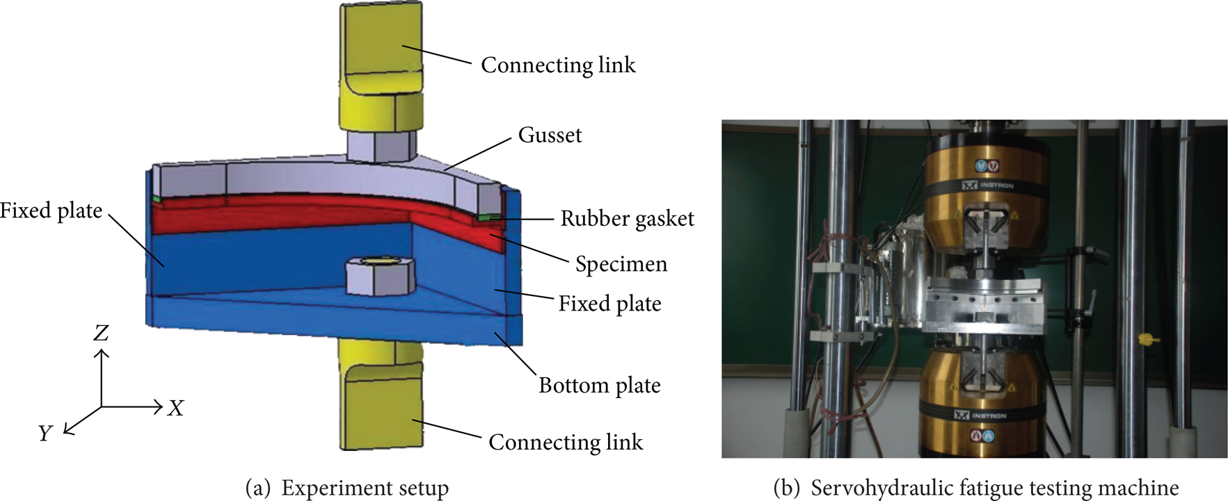
Experiment setup and testing machine.
3.3. Fatigue Test
Two specimens were statically tested with single-side and double-side design, respectively. Twelve specimens were fatigue tested and divided into two groups named S and D according to different designs. Each group has 6 specimens. At room temperature, all the specimens were tested on a servohydraulic fatigue testing machine (Instron 8802, as shown in Figure 3(b)). The stress ratio
4. Finite Element (FE) Model
4.1. Description of the FE Model
In this study, 3D FE models were developed. The ABAQUS/standard finite element package was used to carry out the analysis [10]. In the ABAQUS element library, ABAQUS linear hexahedron reduced integration elements; C3D8R (three-dimensional eight nodded continuum elements) was used to mesh the model. Both of the two models contain three parts, the specimen, the clamping fixture, and the blots (as shown in Figure 4).
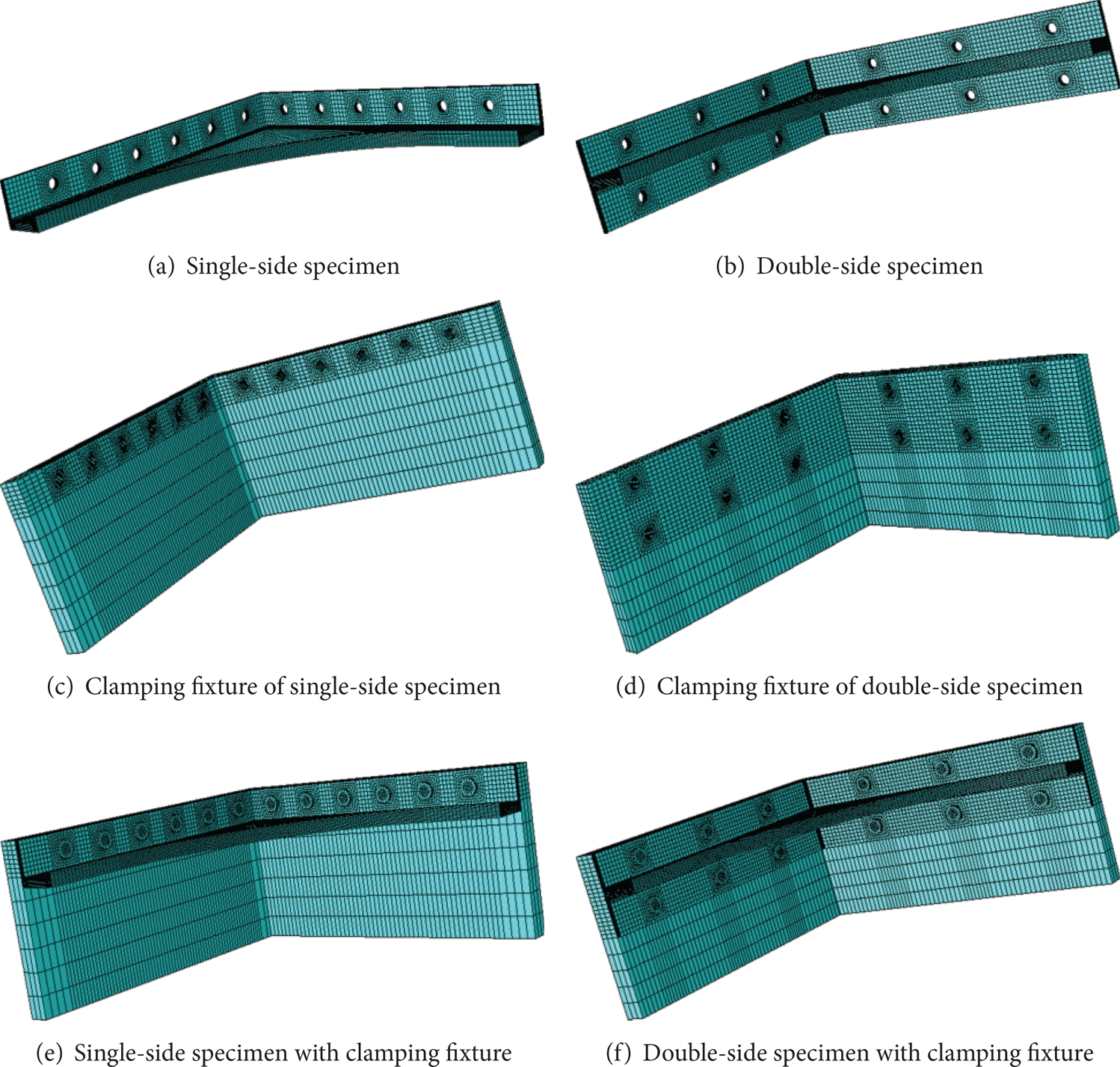
FE models of door frames.
The type of attachment used on the surface of clamping fixture was “TIE,” and it was also used among specimen, clamping fixture, and bolt. The normal contact between specimen and clamping fixture was defined as “Hard contact.” The coefficient of coulomb friction in tangential direction is 0.2.
4.2. Constraint and Load
According to the test, the lower surface of the clamping fixture was fully constrained, while the side and upper surfaces are free. The uniform load applied on the surface of the specimen is 1 MPa. The conditions of constrain and load are shown in Figure 5.
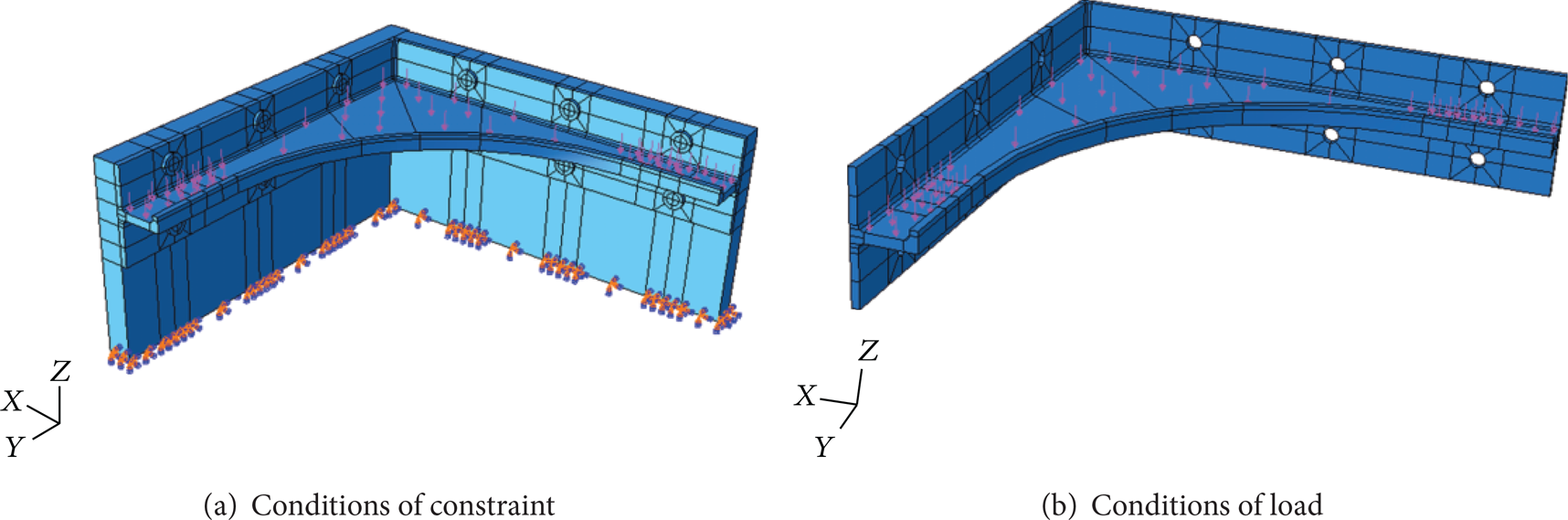
Conditions of constraint and load.
5. Result and Discussion
5.1. FEM Results
The FEM results are shown in Figures 6 and 7. Figure 6 shows that the stress concentration of the double-side specimen occurred in the bevel of specimen under the first hole and the second hole, with the Mises stress of 178.5 MPa and 162.2 MPa, respectively. Figure 7 shows that stress concentration of the double-side specimen occurred in the bevel under the second hole and the third hole, with the Mises stress of 232.6 and 213.2 MPa, respectively. For the single-side specimen, the maximum Mises stress around the hole occurred in the left side of the third hole, with the Mises stress of 85.2 MPa and the normal stress σ33 = 85.0 MPa. For the stress of hole edge of double-side specimen, the maximum Mises stress occurred in the left side of the first hole, with the Mises stress of 80.8 MPa and the normal stress σ33 = 79.6 MPa. It is shown that the door frame using double-side design can reduce the stress concentration around the bevel of specimen effectively. For the stress around the hole edge, the stress concentration was reduced obviously with the design of double side.

FEM results of double-side specimen.

FEM results of single-side specimen.
5.2. Text Result
Only one specimen was provided for each type for static test, and the failure loads were shown in Table 1.
Failure load of static test.

5.2.1. Fatigue Result
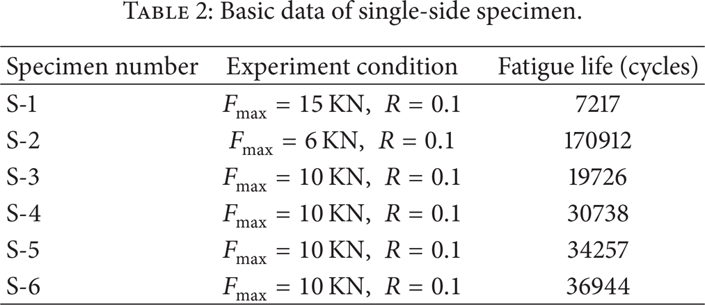
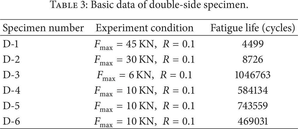
The number of each group of specimen for fatigue test is 6, and the basic data of each group were shown in Tables 2 and 3.
Basic data of single-side specimen.
Basic data of double-side specimen.
5.2.2. Fatigue Contrast Analysis
Calculation of the basic data and the analysis result of the fatigue lives in the same stress level (10 kN) were shown in Table 4 and Figure 8.
Analysis result of fatigue lives.


Analysis result of fatigue lives.
Table 4 and Figure 8 showed that the average life of double-side specimens is increased by 20 times.
5.2.3. Fatigue Numerical Analysis
(a) Logarithm Fatigue Life. All the fatigue lives in the same stress level were shown in Table 5.
Logarithm fatigue lives.

(b) The Mean Value
For single-side specimen,
For double-side specimen,

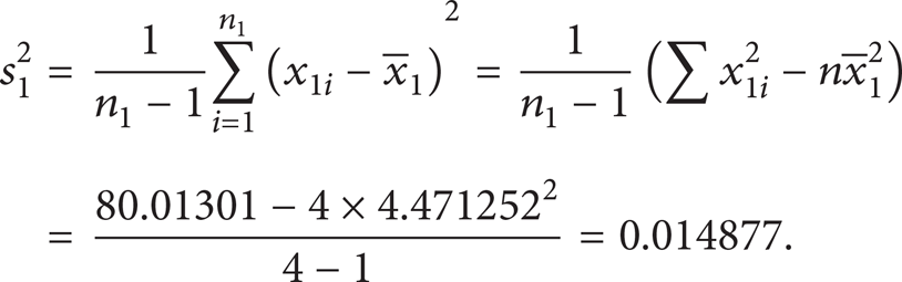
(c) F Check. The F check should be done before the t check. The value of F can be obtained by using s12 and s22 as follows [11]:
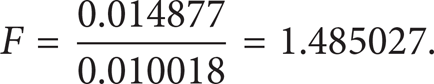
The degree of freedom of molecule is 4 – 1 = 3 and the degree of freedom of denominator is 3 – 1 = 2. Take α = 5%; then Fα = 16 [11]. As F < Fα, it can be known that the standard deviation is equality.
(d) t Check. Calculation the value of t is by reference [11] as follows:
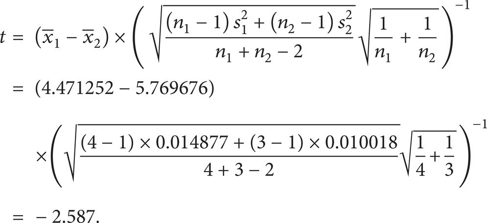
The degree of freedom is ν = n1 + n2 – 2 = 4 + 3 – 2 = 5; take α = 5%, tα = 2.571 [11]. As |t| > tα, the conclusion can be that the contrast of fatigue life of the two different specimen is obvious, and, as
(e) Interval Estimation. Take γ = 95%; then tγ = 2.571 by reference [11]. As

The upper limit and lower limit of confidence is

The interval estimation under 95% degree of confidence is

The equation can be as follow:

Make each item of the above equation antilogarithm as follows:

The above equation shows that the fatigue life of double-side frame is 18–21 times that of the single-side frame with 95% degree of confidence.
5.3. Fracture Analysis
After the fatigue test, the optical microscope was used to analyze the fracture of the specimen. Cracks of single-side specimen (Figure 9) were found in the lower parts of the second hole and the third hole, which agreed well with the FEM result. Besides, the propagation direction of crack was cross as shown in Figure 10.

Cracks of single-side specimen.
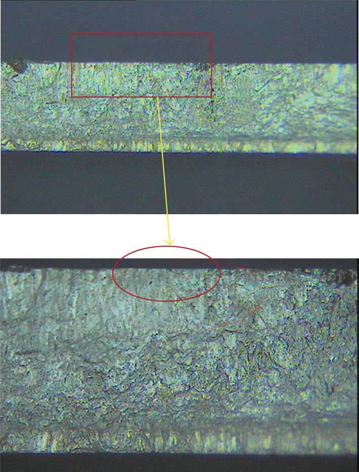
Typical fracture surface of single-side specimen.
Cracks of double-side specimen (Figure 11) were found in the lower parts of the first hole and the second hole, which agreed well with the FEM result. Besides, the propagation direction of crack was lengthwise as shown in Figure 12.

Cracks of double-side specimen.

Typical fracture surface of double-side specimen.
6. Conclusions
A series of experiments were conducted on Aluminum alloy 2024 door frame with different designs to investigate their fatigue behaviors. The conclusions can be drawn as follows.
The static strength of the double-side structure is obviously higher than that of the single-side structure.
The FEM results show that the door frame in double-side design can reduce the stress concentration around the bevel of specimen effectively. The stress concentration around the hole was reduced obviously by adopting the double-side design.
It is verified by F check and t check that the fatigue life of the double-side design is obviously longer than that of the single-side design.
The interval estimation shows that fatigue life of double-side frame is 18–21 times that of the single-side frame with 95% degree of confidence.
After the fatigue test, the optical microscope was used to analyze the fracture of the specimen, and the results agreed well with the FEM results. The crack propagation directions were also obtained for the two types of specimens.
Footnotes
Acknowledgments
This study is supported by the National Natural Science Foundation (no.: 51175424), the 111 Project (no.: B07050), and the Basic Research Foundation of Northwestern Polytechnical University (no.: JC20110257).