
Abstract
The performance of liquid gallium and water in the double layer microchannel has been analysed using three-dimensional conjugate heat transfer analysis. The effect of flow rate on the counter and parallel arrangement of each fluid is studied for three different lengths. Furthermore, cooling capability of liquid gallium and water is compared at the same length with flow rate and pumping power as governing parameters. The performance of fluid was judged on the basis of maximum temperature attained and minimal temperature variations at the heated region. Interesting results have been found showing the effect of specific heat on the type of arrangement for liquid gallium with similar observation for water for low Reynolds number and relatively longer length. Among liquid gallium and water, above certain pumping power use of liquid gallium is found to be favourable for a shorter length of the double layer microchannel. Furthermore, the range of flow rate and pumping power showing superior performance with water was found to increase with the length.
1. Introduction
In recent times, the demand for high computational speed has increased significantly. With market forces pushing for miniaturization and high performance, the current trend in microprocessor architecture has focused on shrinking the processor size, use of high-speed transistors, and increasing clock speeds (higher frequency) which has escalated power density levels [1]. Despite reduction in the voltage levels and capacitance with miniaturization, there has been a substantial growth in the spatial density and operating frequency of the microelectronic devices. According to the International Technology Roadmap for Semiconductors (ITRS), peak power consumption in high performance desktop applications will rise to 198 W by 2015 [2]. High current values also generate large amount of heat due to Joule heating, (defined as I2R, where I is current and R is resistance), within the electronic package and interconnection systems. These factors tend to increase operating temperatures above desired limit and thereby degrading the performance of active and passive components. Ram Viswanath et al. [3] described the need to maintain low operating temperature for two reasons. Firstly, the reliability of circuits (transistors) is exponentially dependent on the operating temperature of the junction. Secondly, microprocessors can operate at higher speeds at lower operating temperatures. These requirements have created demand for more efficient thermal management.
The conventional methods such as air-cooling, heat pipes, vapour chambers, jet impingement, and thermoelectric cooling [4–9] seem to have reached their practical limits creating the need for new cooling techniques. For power dissipation by heat fluxes above 1 MW/m2, liquid immersion and liquid cooling using microchannel cooling device are the most suitable [10]. However, direct integration of microchannels on the heat-generating substrate prevents any thermal contact resistance which makes them favourable over other solutions available in the same heat flux range. High heat transfer phenomenon in microchannels is attributed to their reduced boundary layer thickness and increased heat transfer area to volume ratio. In addition, temperature gradients in the substrate are considerably reduced. Furthermore, very high heat transfer coefficients of the order of 103 W/m2K or more are possible owing to significantly smaller hydraulic diameter in case of microchannels.
Tuckerman and Pease [11] were the first who demonstrated the concept of microchannel cooling. The detailed equations for designing microchannel geometries were provided by Philips [12] who also analyzed heat transfer and fluid flow processes in microchannels. Following this, many researchers have tried to investigate friction and convective heat transfer characteristics in microchannels experimentally [13–15] as well as numerically [16, 17]. Work on various microchannel geometries has been extensively reviewed in [18–20]. The concept of microchannel cooling was further extended by Vafai and Zhu [21] from single layer to double layer microchannel, which consisted of two layers of heat sink to minimize temperature variations in the substrate. This is necessary to avoid large temperature gradients which produce thermal stresses due to mismatch of coefficient of thermal expansion. Using water as a cooling medium, they showed that for small temperature variations in the chip, pressure drop required in case of double layer design is considerably smaller than single layered structure. Wei et al. [22] studied in detail the effect of coolant flow direction, flow rate, and nonuniform heating for stacked microchannel heat sink experimentally and numerically. For the range of flow rate tested, their results favoured parallel flow arrangement for maximum temperature (under the chip) which contradicts the studies of Vafai and Zhu [21]. However, for better temperature uniformity counter flow arrangement was favoured. Levac et al. [23] analyzed the performance of counter and parallel flow arrangements numerically and concluded that for low Reynolds number (Re < 100), thermal resistance offered by parallel flow is less than counter flow arrangement. In terms of uniform temperature distribution, their results agreed with those of Wei et al. [22]. Furthermore, Wei and Joshi [24] numerically investigated stacked microchannel heat sink. For given heat removal capacity of heat sink, they showed that the required pumping power is significantly lower for stacked microchannels with more than two layers as compared to a single layer microchannel. Chong et al. [25] optimized single and double layer counter flow heat sinks based on thermal resistance approach and found that under preset conditions, both single and double layer counter, flow heat sink systems perform better in laminar region than in turbulent regime. Optimization study of the stacked microchannel heat sink was also carried by Wei and Joshi [26]. They investigated the effect of length and number of layers in the stack. For optimized microchannel, reduction in thermal resistance was observed with increasing power and decreasing microchannel length.
The work of various researchers described above has been carried out using water as a cooling medium. Despite water possessing excellent properties to be an ideal candidate suitable for cooling purposes such as high specific heat and low-cost, its low thermal conductivity is a major drawback. Liu and Zhou [27] proposed the use of liquid metals with low melting point for cooling of high power density devices due to their high thermal conductivity. Ma and Liu [28] reviewed in detail all the possible liquid metal coolants with high thermal conductivity that may be used for high flux cooling. Liquid gallium and its alloys were considered the most suitable owing to their overall superior thermophysical properties such as high thermal conductivity, low melting point, nontoxic nature, and low vapour pressure. Its boiling point is greater than 2200°C eliminating power density as limiting factor in cooling applications. Furthermore, it is truly a single-phase system thereby reducing leakage possibility. Miner and Ghoshal [29] experimentally showed that heat transfer coefficients of the order 10 W/cm2/K are achievable using gallium alloy, Ga68In20Sn12. Li et al. [30] performed experiments with different flow and heat dissipation rates using liquid gallium. They observed that the temperature dropped from 70°C to 46.7°C in case of liquid gallium as compared to 51.9°C with water. In addition, while using liquid gallium, the need for smaller radiator size was observed making it suitable for compact chip-cooling device. Owing to their high thermal conductivity, use of liquid metals as base fluids for making nanoliquid-metal coolant was proposed by Ma and Liu [31]. Using various theoretical models for characterizing nanofluids, thermal conductivity enhancement in liquid metal with the addition of more conductive nanoparticles like gold, silver, copper, and carbon nanotubes was analyzed. They also evaluated the effect of particle size and volume fraction. Using Bruggeman model, they found that thermal conductivity of fluid increased by 2.3 times with carbon nano-particles for volume fraction of 20%.
Irrespective of all the advantages of liquid metals discussed so far, the fact that their specific heat is low can cause an increase in their temperature more rapidly as compared to water. Deng et al. [32] experimentally discussed this issue by comparing the use of liquid metals and water in a single layer microchannel. They found that the use of liquid metal is beneficial in high flow conditions. However, no results have been reported in the literature comparing the performance of liquid gallium and water in double layer configuration to the best of our knowledge.
In the present study, three-dimensional double layer microchannel was modelled and simulated for conjugate heat transfer analysis. The performance of liquid gallium and water has been compared in their counter and parallel arrangement for three different lengths of microchannel. A detailed analysis has been carried out to gain insight into the reasons affecting the choice of arrangement for each fluid. The purpose of this study is also to investigate the effect of length on the choice of fluid for double layer microchannel. For this, the performance of both fluids has been compared at the same length under the conditions of the same flow rate and power.
2. Analysis
2.1. Computational Model
Figure 1 shows double-layer microchannel heat sink along with the coordinate system. Counter and parallel arrangements are depicted using arrows along the flow direction. The three-dimensional computational domain is illustrated in Figure 2. Owing to symmetry conditions, only half of the double layer microchannel has been included in the computational domain. Origin of the coordinate system is assumed to be at the center of the base of the upper heat sink. The cross section of the geometry used in this analysis is the same as that used by Vafai and Zhu [21]. Similarly, the lengths selected for analysis lie within the maximum length covered in the same study. Hch and Wch represent the height and width of each channel, respectively. Htotal and W denote the total height and width of the computational domain, respectively. W s is the thickness of solid region while L1, L2, and L3 represent three different lengths considered for analysis. The length of microchannels selected is from the study. All the dimensions used in the analysis have been defined in Table 1.
Various dimensions used in analysis (in μm).


Schematic of double layer microchannel.

Three-dimensional computational model used in analysis.
The analysis is based on the following assumptions.
Steady state flow.
Incompressible fluid.
Laminar flow.
Constant properties of both fluids and solid.
Effects of viscous dissipation are negligible.
Based on the above assumptions the governing equations of mass, momentum and energy as applied to the fluid region were
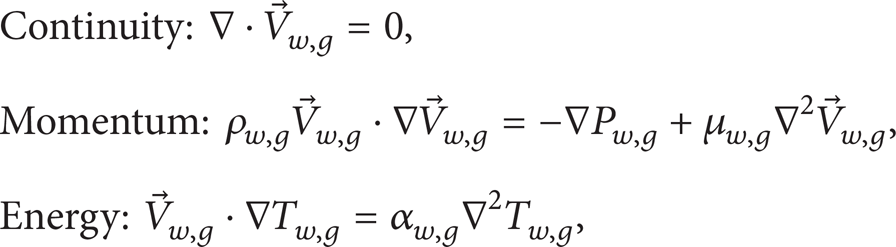
where the variables

where T s represents the temperature of solid with subscript s denoting solid region.
Reynolds number, Re, is defined as

where
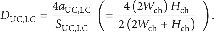
Here a and S, are the area and perimeter of the channel, respectively. Hydraulic diameters of upper and lower channel have also been tabulated in Table 1.
2.2. Boundary Conditions
Figure 3 depicts the boundary conditions applied to the double layer microchannel. Uniform heat flux, q″ (−106 W/m2), is applied at the base, at y = – 145 μm. As the top of heat sink cover is usually made of poorly conducting material, adiabatic conditions were assumed at the top surface, that is, at y = 115 μm. The entrance and exit walls of the solid region were also assumed to be adiabatic considering heat transfer due to fluid as dominant factor. Similarly, adiabatic conditions were assumed at the outer wall of solid region owing to symmetry condition. In fluid region, the fluid entered the channel with uniform velocity and temperature at the inlet. In case of counter flow arrangement, inlet for lower channel is at z = 0 and for upper channel at z = 1250 μm, 2500 μm, and 5000 μm in case of L1, L2, and

Boundary conditions.
The solid region was assumed to be made of silicon. Table 2 lists all the material properties used in this present study. Since melting point of gallium is 29.8°C (≈303 K) [28], the inlet temperature of both fluids was assumed to be 305 K. To account for different mean temperatures of both the fluids, the properties of liquid gallium and water at 313 K and 308 K, respectively, were used in this study.
Material properties.

From [35].
From [36].
2.3. Solution Method and Grid Independence
The continuity, momentum, and energy equations were solved using general-purpose finite-volume-based commercial code, FLUENT. The standard scheme for pressure discretization and SIMPLE algorithm for pressure velocity coupling were used. The momentum (convergence criteria 10−6) and energy equations were solved with the second-order upwind scheme with (convergence criteria 10−8). For grid independence, three grid sizes were tested separately for liquid gallium and water at the same flow rate. Counter flow arrangement was used for all the three lengths; that is, flow in lower and upper channel was assumed to be in positive and negative “z” direction, respectively. The grid sizes used for all three lengths have been described in Table 3. For comparing deviation in results for different grid sizes, relative error was defined as

where Variable denotes temperature or velocity, the subscript ii represents grid size, and Variable
Grid sizes (x × y × z) used for computations.

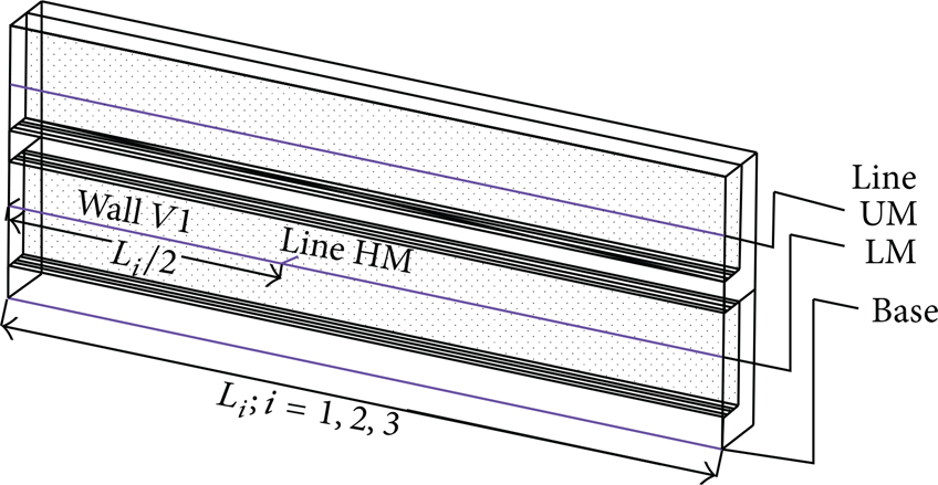
Position of lines HM, UM, LM, base, and wall V1.

Absolute value of relative error in fluid velocity in lower channel along line LM for length L3 (−5000 μm).
3. Results and Discussion
Heat transfer from solid to liquid depends on the heat transfer coefficient which can be expressed by the following relation [33]:
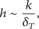
where h is the heat transfer coefficient, k is the thermal conductivity of the fluid and δ T is the thickness of thermal boundary layer. The thickness of the thermal boundary layer for flow in ducts, as in this study, at any position “z” from the entrance is defined as [33]

Here Pr represents Prandtl number and this relation is valid for “Pr ≫ 1” (water) and “Pr ≪ 1” (liquid gallium). From the above relations, it is clear that the heat transfer coefficient increases with flow rate due to increase in the thermal developing region. At a constant flow rate, high value of k enhances heat transfer due to increase in heat flow in axial and radial (x and y in our case) directions. However, a large value of k decreases the thermal developing regime of fluid. This explains negligible thermally developing region as compared to the overall length of microchannel in case of liquid gallium owing to its high thermal conductivity. On the contrary, thermal boundary layer remains in developing state for significant flow region when using water as a cooling medium. For short microchannels, developing regime may be observed throughout the length. Therefore, at the same flow rate, thickness of the thermal boundary layer is the main factor affecting h in case of water while k is the primary factor for liquid gallium.
The performance of each fluid in counter and parallel arrangement is discussed first followed by a comparison between water and liquid gallium at the same length of the double layer microchannel. Since the density of liquid gallium is about six times that of water, the performance of both the fluids has been compared at the same flow rate and power. The range of total flow (sum of flow in both the channels) considered for comparison varies from 0.6 × 10⁻⁸ m3/s to 3.6 × 10⁻⁸ m3/s, which corresponds to Reynolds number 122 to 732 for liquid gallium and 42 to 252 for water in each channel. For comparison at the same power, two additional flow rates of water (5.4 × 10⁻⁸ m3/s and 7.2 × 10⁻⁸ m3/s), corresponding to their Reynolds number 378 and 504, were also considered. The results corresponding to these flow rates have also been illustrated while comparing the type of arrangement of water. The following abbreviations have been used extensively for the sake of simplicity, “PF” for parallel flow, “CF” for counter flow, “UC” for upper channel, and “LC” for lower channel and L1, L2, and L3 representing length of the microchannel. The term flow rate has been used instead of total flow rate for similar reason. Also, otherwise specified, the legends in the figures are identified as AF-M, where A and M represent type of arrangement (P for parallel and C for counter) and cooling medium (G for liquid gallium and W for water), respectively.
3.1. Counter and Parallel Arrangement of Respective Fluid
In this section, the type of arrangement suitable for each fluid is investigated. Figures 6(a) and 6(b) show the maximum base temperature reached at various flow rates, for all three lengths using liquid gallium and water, respectively. It is observed that maximum base temperature attained is lower in parallel configuration with liquid gallium for all lengths and flow rates. Since similar explanation holds for all the cases of liquid gallium, illustrations have been made for flow rate corresponding to Reynolds number 366 (1.8 × 10⁻⁸ m3/s) for L2 length. Figure 7 shows the temperature along lines UM, LM, and base (as depicted in Figure 4) for both arrangements. It is observed that throughout the length in PF, the temperature of the base and liquid gallium in LC is higher than its temperature in UC. Moreover, downstream, variation in temperature difference between liquid gallium in both the channels and base is negligible. This is further exemplified in Figure 8(a) showing temperature contours at various cross sections along the flow length in PF. This shows heat transfer in PF with liquid gallium takes place in usual manner, which can be described as that follows: heat flows from base to fluid in both the channels in addition to flow from fluid in LC to UC.

Maximum base temperature attained versus flow rate for all lengths using (a) liquid gallium. (b) Water.
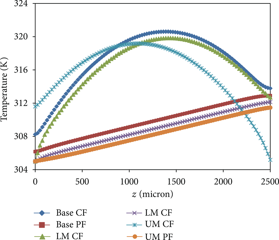
Temperature at lines UM, LM, and base for L2 (−2500 μm) for parallel and counter configurations with liquid gallium.

Temperature contours at various cross sections along length, L2 (−2500 μm) using liquid gallium for (a) PF. (b) CF.
Similar to PF, temperature contours at various cross sections for CF are shown in Figure 8(b). It can be deduced that, unlike PF, the temperature difference between liquid gallium in both the channels as well as base varies significantly. This is maximum at the inlet of both the channels and minimum near half the length resulting in maximum heat transfer at the former. Due to large amount of heat flow from the base to liquid gallium at the inlet of both the channels and its low specific heat, its temperature in both channels increases rapidly. Large temperature difference between liquid gallium in both the channels also adds to heat transfer from one channel to another. As a result, the temperature of liquid gallium in UC exceeds the base temperature towards the exit as can be seen in Figure 7. This phenomenon may be explained by the following reason. In general, for CF, maximum heat transfer occurs at the inlet of both the channels. As a result, the temperature of the fluid in both the channels increases for nearly half their respective downstream length, following which, redistribution of heat takes place among the fluids in both channels for the remaining length. However, if the temperature difference between fluids is not sufficient for efficient redistribution, the temperature of fluid in a channel may exceed the base temperature, as observed in the case of liquid gallium. Inadequate temperature difference may be attributed to its low specific heat which results in a rapid increase in its temperature. Furthermore, this may result in heat flow from fluid to solid region. This explanation is supported by Figures 9(a) and 9(b), illustrating heat fluxes at the solid wall for PF and CF. The following sign convention is followed, and heat gained by the system is positive and negative otherwise. Considering solid wall as a system, heat flux outflow (carried away by fluid) is negative. The positive flux denotes heat transfer from fluid to solid region. It can be seen that heat flow into the solid takes place for a considerable length in CF, thereby reducing the effective heat transfer region resulting in poor performance of counter arrangement. It is to be noted that even though the region of positive flux is also observed in PF, this is primarily confined only to the upper horizontal wall of lower channel, that is, y = – 15 μm. This is due to the flow of heat from liquid gallium in LC to UC. This results in efficient heat redistribution and hence superior performance of PF.

Positive heat flux, qpos, at solid wall in LC and UC using liquid gallium for (a) PF. (b) CF.
With water as a cooling medium, the performance of counter arrangement is better for most of the cases, as can be seen from Figure 6(b). This can be explained due to large specific heat of water, nearly ten times that of liquid gallium. High specific heat of water prevents significant rise in its temperature despite large heat transfer at inlet. Consequently, the temperature of water in both the channels remains well below the base temperature. Better performance in CF may also be explained by the following reason. For PF, h decreases in both the channels downstream, with development of thermal boundary layer. On the contrary, minimum thermal boundary layer in both the channels occurs at opposite ends in CF. This means that, for almost entire length, h in UC and LC is different at any position along the length. Hence, in PF, convective resistance at all positions is nearly the same in both the channels, whereas it varies in CF providing an alternate least resistance path which results in its superior performance.
At a very low flow rate (Re < 50) of water, PF shows better results for L3 length as shown in the inset of Figure 6(b). Here, point “B1” represents the flow rate below which PF gives better performance for length L3. It is to be noted that B1 obtained here is owing to limited number of flow rates considered. The exact value may require more points or even some function relation of maximum base temperature with flow rate for PF and CF. Levac et al. [23] explained this phenomena on the basis of negative flux (positive in our study). However, no such observation is made for lengths L1 and L2. Therefore, it can be deduced that with water as a coolant, for each length of microchannel there exists a threshold flow rate up to which PF shows superior performance. Furthermore, this threshold flow rate is proportional to the length of the double layer microchannel. This means, for desired maximum temperature attained at the base and given length of double layer microchannel, the threshold flow rate will be important criteria for deciding the type of arrangement, especially for longer lengths. For short length, this flow rate may be too small to be practically feasible thereby favouring counter configuration in such cases. As explained in the case of CF for liquid gallium, heat flow occurs from fluid to solid when the temperature of fluid in one of the channels rises above the base temperature. Figure 10 shows the temperature at z-plane at z/L3 = 0.05 and 0.95. As clearly seen, the temperature in UC and LC is higher than that of base at z/L3 = 0.05 and 0.95, respectively. This also shows that the performance of water is also affected by its specific heat for longer double layer microchannel at very low flow rate. With an increase in flow rate, temperature rise in the water decreases due to a reduced interaction of water with heated region. Moreover, higher flow rate corresponds to higher mass flow rate and hence greater heat storing capacity as compared to low flow rate. Therefore, temperature of fluid in any channel does not rise above the base temperature resulting in superior performance of CF. Similarly, for shorter length, temperature rise in water is not high enough to affect efficient distribution of heat at low flow rate. Consequently, temperature of water remains well below that of base and shows superior performance of CF.

Temperature at z/L3 = 0.05 and z/L3 = 0.95 plane.
3.2. Fluid Comparison at the Same Length
The performance of both the fluids for the same length of double layer microchannel has been discussed in this section. The cooling capability is discussed on the basis of maximum temperature reached at the base with each fluid under the conditions of same flow rate and pumping power.
3.2.1. Comparison at Same Flow Rate
As per the above discussion, parallel configuration gives better results for liquid gallium in all the cases while for water the configuration depends on the length and flow rate. With water as a cooling medium, CF is favoured for L1 and L2 while for L3, the choice depends on flow rate. Therefore, illustrations for PF with water for L1, L2, and CF with gallium for all lengths have been omitted for the sake of brevity.
Figures 11(a), 11(b), and 11(c) depict maximum base temperature achieved at various flow rates with PF liquid gallium and CF water for length L1, L2, and L3, respectively. Superior performance of liquid gallium is observed beyond a certain flow rate which is marked by point B2 in the illustrations. This means that, for a given length of the double layer microchannel, the effect of thermal conductivity of liquid gallium for high heat transfer increases after a minimum flow rate. This may be due to complex heat transfer phenomena in the conjugate heat transfer problem. It is well known that the flow of heat takes place along the path of least thermal resistance, which depends on thickness of the thermal boundary layer for heat transfer from solid to fluid. Convective resistance near the corner regions is due to the interaction of the thermal boundary layer along two adjacent walls. Depending on the fluid and flow conditions, this resistance may be greater than thermal conduction resistance to heat transfer through the substrate. This has been explained by Fedorov and Viskanta [34]. Consequently, heat enters the solid substrate bypassing the fluid region, instead of proceeding towards the core fluid region. This local heat flow across adjacent walls affects uniform heat transfer from solid to fluid as well as uniform heat distribution in the substrate, thereby affecting the fluid performance.

Maximum base temperature attained with liquid gallium and water at different flow rates for length (a) L1 (−1250 μm). (b) L2 (−2500 μm). (c) L3 (−5000 μm).
To gain deeper insight into the affect of this phenomenon on fluid performance in our study, total positive heat flux on wall V1 was calculated and normalized for each fluid. It is to be noted that on wall V1, positive flux observed near the corner region can be explained because of the above phenomena. This is illustrated in Figure 12 for PF liquid gallium and CF water for flow rate 0.6 × 10⁻⁸ m3/s and L2 length. With water as a cooling medium, developing thermal boundary layer may result in lower convective resistance for considerable flow length. Near the exit, sufficient development of the thermal boundary layer increases the thermal resistance which results in the above phenomena. Total positive heat flux on wall V1 at a particular flow rate is defined by the following equation:

where q is heat flux, superscript “pos” represents its positive value, and V1 denotes wall location. Figure 13 shows normalized positive flux for both fluids at different flow rates.

Positive heat flux at wall V1 of lower channel, qpos, V1.

Normalized total positive heat flux of both fluids at wall V1, qnormalizedV1, versus flow rate for length L2 (−2500 μm).
It is observed that local positive heat flux decreases with increase in flow rate for both fluids. Furthermore, the rate of its decrease with flow rate is greater in case of liquid gallium. This means that for liquid gallium, the effect of local positive heat flux decreases as compared to water with increase in flow rate. In addition, the effect of its high thermal conductivity becomes predominant resulting in a higher heat transfer which explains superior performance of liquid gallium at higher flow rates.
Another important observation is that there is increase in minimum flow rate beyond which performance of liquid gallium is better, with increase in length. This can be explained on the basis of change in thermal resistance with change in length at a constant flow rate. We define thermal resistance, Rth, as

here Tbase, max is maximum base temperature and Tf, in is the fluid inlet temperature. Change in thermal resistance is expressed as

where Rth: j + 1, j represents difference of thermal resistance at “j + 1” and “j” length at the same flow rate. For example, Rth: 2,1 means difference of thermal resistance for length L2 and L1 at the same flow rate. Figure 14 shows change in thermal resistance for PF liquid gallium and CF water. The legends are identified as AF-M-R, where R represents Rth: j + 1, j and the others have the same meaning as mentioned earlier. At the same flow rate, larger change is observed for liquid gallium. This means that, at the same flow rate, the thermal resistance offered by liquid gallium exceeds that of water with increase in length. This explains increase in minimum flow rate, beyond which better results are obtained with liquid gallium, with increase in length.

Change in thermal resistance versus flow rate for PF liquid gallium and CF water.
3.2.2. Comparison at the Same Pumping Power
In practical systems, pumping power limits the flow rate and hence affects the performance of the fluid. If no restriction is imposed on pumping power, the flow rate can be increased to any desired limit, which is not practically favourable. Therefore, comparison of pumping power is an important issue which needs to be addressed. This section examines the effect of pumping power on base temperature for all lengths. Similar to the above discussion, only PF liquid gallium and CF water have been considered due to their better performance in the majority of the cases. Pumping power (PP) is defined as

where Q F and ΔP represent flow rate and pressure drop across a channel while subscript F represents flow. Due to similar flow conditions in both the channels, pumping power for each case can be expressed as

Figure 15 plots maximum base temperature versus pumping power. As mentioned earlier, for comparison under this category, two additional flow rates of water were also considered. To account for significant variations, pumping power has been represented on log axis with base 10. It is observed for L1 length that performance of liquid gallium surpasses that of water only after a certain minimum pumping power, say critical power. Similar inference can be derived for L3 length for which critical power is quite high. Higher pumping power corresponds to higher flow rate and hence large pressure drop. On low pumping power, high density and larger local positive flux affect the performance of liquid gallium, as explained in the above section. In addition, due to enhanced interaction of fluid with heated region, the effect of specific heat is dominant as compared to thermal conductivity. Even with an increase in flow rate beyond which the effect of local positive heat flux and specific heat begins to drop off, high density of liquid gallium negates its use due to larger pressure drop. For longer length, use of liquid gallium becomes significant only at higher pumping power. It can also be deduced that for a longer length of the double layer microchannel, water can be used for a wider range of pumping power.

Maximum base temperature attained versus pump power (PP). Pumping power being represented on log scale (with base 10).
3.3. Performance Comparison on the Basis of Minimum Temperature Variations
So far, the performance in all the cases is evaluated based on the basis of maximum base temperature attained. However, over a period, temperature gradients in the substrate also affect the performance of microchannels to a large extent. Large temperature gradients may cause uneven expansion/contraction in the substrate. Consequently, thermal stresses accrue over a period of thermal cycling which weakens the structure and may cause premature failure of the component. Hence, the performance of both fluids also needs to be evaluated under this criterion which is discussed briefly in this section.
Figures 16(a) and 16(b) show temperature variation, ΔTbase, (defined by difference of maximum and minimum base temperature for respective case) at the base for liquid gallium and water for all lengths. Better results are observed with PF gallium and CF water. The comparison at the same length is shown in Figure 17. Like the previous section, only better performing configurations have been illustrated in Figure 17. It can be clearly seen that, in terms of temperature uniformity, water gives superior results at all lengths.

Variation in base temperature, ΔTbase, with flow rate for all three lengths using (a) liquid gallium and (b) water.
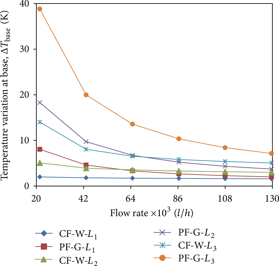
Variation in base temperature, ΔTbase, versus flow rate for all lengths using liquid gallium and water.
Minimum temperature occurs where the maximum heat flow takes place from the base to the fluid which depends on the difference in temperature of the base and fluid. In case of PF, the temperature of the fluid is minimal in both the channels near the entrance region, resulting in maximum heat transfer from base. High heat transfer at the inlet in PF can also be explained on the basis of developing thermal boundary layer. For region near the inlet, thickness of the thermal boundary layer being minimal in both the channels offers the least resistance, as compared to any other region in flow regime. This favours large heat flow from the base leading to minimum base temperature near inlet region. However, for CF, near the inlet region (z = 0), temperature of water in the UC is not at its minimum value. This reduces the overall effective temperature difference available for heat flow from base to fluid. As a result, higher minimum base temperature is observed as shown in Figure 18 explaining low temperature variation at base with CF water. In case of liquid gallium, its low specific heat suppresses the advantage of counter configuration. Though minimum base temperature increases in CF as compared to PF, similar to water, rise in maximum base temperature in CF is far more than that in PF. This results in higher temperature variations in CF liquid gallium. Furthermore, this also explains better performance of water while comparing at the same microchannel length.

Minimum base temperature versus flow rate for all lengths with water.
4. Conclusion
The performance of liquid gallium and water in their parallel and counter configurations is compared at different lengths. In addition, cooling capability of both the fluids at the same length is analyzed at the same flow rate and pumping power. It is found that parallel configuration is more suited for liquid gallium at all flow rates and lengths, both in terms of maximum base temperature attained and minimal temperature variations. However, in water the type of configuration is found to be dependent on microchannel length. For longer channels, 5000 μm in this study, parallel configuration is suitable at low flow rate. Poor performance of counter configuration is due to increase in fluid temperature above base temperature. These observations indicate a significant effect of specific heat of the fluid on its cooling capacity. With pumping power as input criteria, use of liquid gallium was found to be worthy only beyond a critical pumping power. Moreover, critical pumping power was found to increase with length of the double layer microchannel. This suggests the use of liquid gallium for small double layer microchannel. For longer length, large pumping power may result in transition from laminar to turbulent region, which needs further investigation. The results indicate that fluid density is also an important parameter in fluid selection under given conditions of the double layer microchannel. In terms of temperature uniformity, water outperformed liquid gallium in all the cases considered.
Footnotes
Nomenclature
Acknowledgments
The authors are thankful to the Director of CSIR-CSIO, for supporting their work. The authors also express their gratitude to Amol P. Bhondekar (CSIR-CSIO), Basant Sikarwar, and Anant Singhal (ISRO) for their valuable inputs and suggestions.