
Abstract
It is important for doctors to see a patient's medical history when the patient visits the hospital. Currently, doctors research and compare information on their patient's condition through the patient or medical history chart. This method can cause confusion when the patient has several namesakes which can lead to medical errors and malpractice. To prevent such accidents, doctors should have access to the accurate history of their patients through an independent recognition system at any time or any place. Examples of such independent recognition systems are the RFID system, a compacted embedded system, and RFID reader and a TFT-LCD monitor with a unified single system. In this study, to record a patient's medical history, an RFID monitoring system with a carrier frequency of 125 kHz a PXA255 ARM chip, and a 64 Mbyte SDRAM was configured and operated as an embedded Linux system. These two systems were interlocked to read the patient's arm tags. The interlocked system can obtain patients' medical history from a database and display it on a monitor. The advantage of this system is that it does not need a computer and can be implemented with only a hand-held device. Its performance analysis chart shows the result from the experimental device and the results shown with photographs.
1. Introduction
Doctors and nurses need a mobile conversion system in a ubiquitous environment in a hospital to see their patient's personal and medical histories [1–4]. An RFID system is first required, however, for recognition of the patient, as is a loaded embedded Linux system for data monitoring. The RFID tag system is essential for patients who wear a tag, as it recognizes a patient's medical history without error [1–4]. The existing real-time embedded Linux operating system is more advanced than the previous system and supports more features, and through its current source, its development speed is fast increasing [5–9]. Judging from these facts, a mobile ability system is required for the design of a patient monitoring system. Its development cost is also lower. An integrated system for the monitoring of the patient's history must be capable of real-time behavior. Moreover, immediately needed tag information for monitoring requires a fast-booting system, and one of the essential requirements for mobile conversion is a low-power mobile system [10–17]. In this study, to monitor RFID data in real time, the RFID system used a 125 kHz carrier wave with the EM4095 and an embedded Linux operating system with a 400 MHz PXA255 ARM RISC chip, a 512 Kbyte Boot Flash, and a 64 Mbyte SDRAM. Moreover, the system was configured to use a NAND Flash [9]. Given the overall system configuration and operating conditions, CC1020 was embedded in the RFID system using a wireless communication system [18–26]. The extended Linux system boot process and the overall boot loader, kernel, and application processes were operated in an orderly manner. In conclusion, the performance was analyzed and shown with pictures of the experimental systems.
2. System Configuration
2.1. System Concept
In Figure 1, tag information is sent to the 125 kHz RFID reader. The received tag data will be sent to the server using the wireless CC1020 module with a 433 kHz frequency [27–29]. The saved data from the server contains the corresponding patient medical history, and the tag information and corresponding data are retransmitted via a wireless module. After such data are received using RS232 communication, they will be transmitted to the embedded system that is equipped with the PAX255 ARM Chip. Based on the QT written monitoring program, the embedded system outputs a history of the patient's medical history to a TFT-LCD.

Block diagram of the overall system.
2.2. System Configuration
2.2.1. RFID System
The RFID system used an EM4095 general purpose chip that was produced by the SWATCH group.
It is a CMOS device that uses the 125 kHz frequency band. The tag in the RFID system was EM4100 and will operate only in the Read-Only mode. Using EM4095, the reader system was set up to operate in the Read-Only mode. Figure 2 shows the circuit configuration of the RFID system.
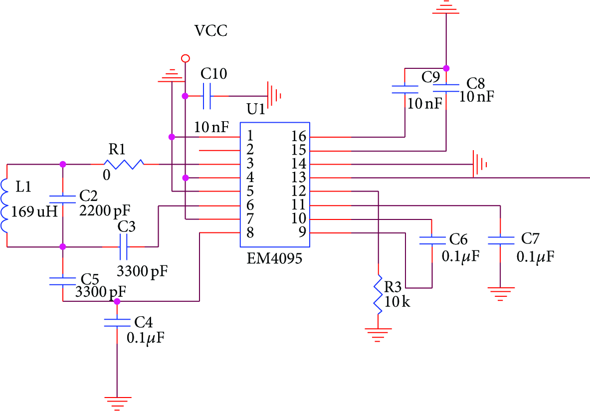
Circuit of RFID system.
L2 in Figure 2 is the antenna that is attached to the reader. Tag data are entered on the antenna of the EM4095 13-pin output. To input the data to the CC1020, Atmega128 MICOM was used.
2.2.2. Wireless Communication System with CC1020
Figure 3 shows the circuit that used the CC1020 chips. One of the important characteristics is shown in the schematic of the PLL circuit using fixed and variable frequencies by synchronous phase and LC filters.

Circuit of transmitter and receiver part of CC1020.
The frequency of a particular band pass was used. CC1020 was needed to set the behavior of the PSEL, PCLK, PDI, and PDO pins and for a bidirectional AVRData interface. The DIO pins DCLK pin connection was required. An almost perfect CC1020 is shown in Figure 4 with synchronous serial interface settings, using the MCU.

Interface between Atmega128 and CC1020.
This interface can be divided into two parts. First, the internal register has to install a CC1020 chip that supports the implementation of a communication system. After the completion of the second set, the actual data are used for transmission and receipt. The interface circuit in Figure 4 explains this process.
2.2.3. Embedded Linux System
EZBOOT was used for the embedded Linux system that was manufactured by Falinux. Its main feature is its ability to memorize, read, and write. It uses ZMODEM to download images and flash memory to read and write. To display the history of the patient information system on the LCD, the embedded Linux system must be initialized. The initialization process should be performed as shown in Figure 5.
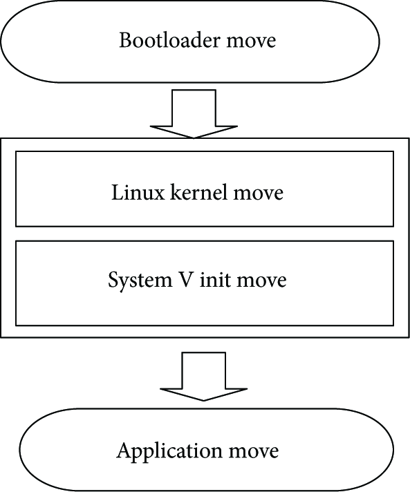
Flowchart for initial process of the embedded Linux system.
At the moment of the initialization of the embedded Linux system, the Boot loader must be executed in 512 Kbytes of the BIOS Boot Flash within sector 0, cylinder 0. The Boot loader will first initialize the hardware for the system to operate, and the CPU will make the access possible to the SDRAM. As shown in Figure 6, the kernel and RAMDISK images are stored in the 64 Mbyte NAND Flash and will be saved in the 64 Mbyte SDRAM.

Boot loader memory map.
Before the kernel is performed for the i386 Linux-2.4.19 to make it apt for ARM usage, ARM patching must be performed. Due to the use of a CPU as a PXA255 chipset, the kernels with the performed XScale must be loaded to the 64 M NAND Flash in the EZBOOT setup mode. The Linux kernel and arch/*/kernel/head.S, which enable the C code to perform the operation, were programmed at the entry point. Moreover, the init/main.c has a start kernel ( ) function, and such function of arch_init, trap_init, is an architecture-dependent initialization function. Each part of the Linux kernel has an initialization function. The start kernel ( ) function at the end of the kernel thread (init,…), as a function of the PID, will create a single kernel thread, and the start kernel ( ) function itself is an idle task. Moreover, the init kernel thread will mount the root file system in the Read-Only mode. At this point, because the embedded Linux system does not have a hard disk, it must load the root file system to the Ram disk. When the Ram disk that serves as the root file system is loaded, the System V init is finally performed. The last kernel performance process in the exec/sbin/init is called the System V init program. It has the same functions and performance as the DOS program of the old, which had autoexec.bat (the Batch file that enabled automatic operation). The System V init and /etc./inittab file perform according to the contents of the inittab file, and the information contents vary depending on such performance. Table 1 shows the Runlevel per performance type, which groups the services into different categories.
A class of runlevel.

In the embedded system, a specific user application, the booting must be carried out simultaneously. Therefore, the RFID tag data must be sent from the system and outputted to the TFT-LCD window immediately after the board booting is completed. Thus, the /etc./inittab file shown in Algorithm 1 was revised.
si::sysinit:/etc/rc.d/rc.sysinit ⋯ ⋯ lc:0123456:wait:/etc/rc.d/rc.local l0:0:wait:/etc/rc.d/rc 0 l1:1:wait:/etc/rc.d/rc 1 l2:2:wait:/etc/rc.d/rc 2 l3:3:wait:/etc/rc.d/rc 3 l4:4:wait:/etc/rc.d/rc 4 l5:5:wait:/etc/rc.d/rc 5 l6:6:wait:/etc/rc.d/rc 6 cp:0123456:wait:/etc/rc.d/rc.app // added this line
The Runlevel of the embedded Linux systems is basically 3, l3:3:wait:/etc/rc.d/rc 3. The execution sequence of inittab is rc.sysinit>>rc.local>>rc3.d. As shown in Table 2, an executable script was added, and in the directory of etc./rc.d that was executed with rc.local, the rc.app application script was made. A brief description of the script follows.
cp script.

3. Experiment and Performance Analysis
Figure 7 shows the future test of RFID systems and the embedded Linux systems in this project. Figure 7(a) shows a reading from the RFID tag system, which indicates that the TFT-LCD can display related data. The PXA255 chip, 64 Mbyte SDRAM, and NAND Flash are configured to be compatible with the embedded Linux system. Moreover, Figure 7(b) shows the capability of the 125 kHz RFID system and server, which are configured to communicate with a wireless communication module, the CC1020 system, to read tag information.
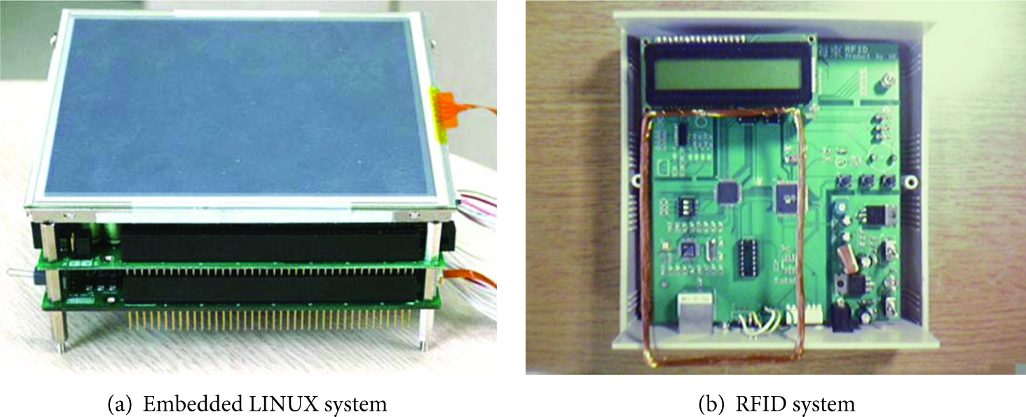
Experiment system.
Figure 8 tag shows that the RFID system has read the data. The output of the TFT-LCD window shows the experiment results of the embedded Linux system.

Display on the TFT-LCD monitoring.
As shown in the picture, if the tag has not made contact with the reader, a basic screen output will be shown like the picture shown in Figure 8(a).
If contact has been made between the reader and the tag, the data are immediately recognized and completed. These data will complete the communication through the server, and the output image will be displayed by the embedded systems of the TFT-LCD screen, as shown in Figure 8(b).
Table 3 shows the performance of the experiment device. The CC1020 transmission of the transferred data among the tag IDs involved removal of the starting byte and the stop byte of the tag ID. After only 8 bytes were removed, the information was transmitted and received. The experiment was repeated 100 times using the system, and no error occurred during the transmission.
System performance.

4. Conclusion
In this study, through a digital wireless communication device, tag information data were transmitted between the client server and the server with an RFID system. Concerning the verified data, a system that could monitor information in real time was developed: the embedded Linux system with a PXA255 ARM chip. The RFID system developed a multichannel, unidirectional, and bidirectional transmission/receiving system using the ISM band. Its distinctive characteristics are low-power consumption, high sensitivity, a small chip, and fewer external components. Therefore, the system showed the possibility of low-power usage and reduced production costs and sizes. Embedded Linux systems are integrated with the RFID tag System, and information must be outputted on a TFT-LCD window and must internally use EZBOOT with 2.4 kernels. This system was developed to simultaneously self-boot and run the QT application, so that it can monitor RFID data. The experiment was performed inside a walled building; and within 50 m, tag data were transmitted 100 times. There were no errors during the tag data monitoring. With this result, this system showed potential application in hospitals.
Footnotes
Acknowledgment
This research was supported by a research program of Dongseo University's Ubiquitous Appliance Regional Innovation Center supported by the Grants from the Ministry of Knowledge Economy of the Korean government and Busan Metropolitan City (no. B0008352).