
Abstract
The aerodynamic characteristics for the vee-tail aircraft configuration have been investigated numerically at low Reynolds number (Re < 106). Three types of vee-tails have been adopted to be compared with the conventional tail type (with horizontal and vertical tails). The results show that the effect created by the vee-tail can greatly affect the aerodynamic characteristics of the whole aircraft. If the dihedral angle of the vee-tail is too large, it can directly affect the flight stability. The main reason for the longitudinal moment curve “moving up” at high dihedral angle can be attributed to the serious asymmetric downwash effect. Based on these, the force variation and the corresponding aerodynamic characteristics for three different sizes of aileron with different deflection angles have also been obtained computationally and analyzed in detail.
1. Introduction
The newly developed vee-tail type, due to its excellent ability of stealth, has drawn the favor of many designers [1–5]. This type of tail can replace the ordinary horizontal and vertical tails and decrease the aerodynamic interferences between the tail and fuselage to a great extent. It can also largely reduce the infiltration areas of tail [6–8]. Both the F-117 (a kind of stealth plane newly developed in USA) and He162 (a kind of light fight developed in Germany) have adopted the vee-tail configuration, and they have comparatively better viability in the war [9].
At present, the research for the vee-tail has been extended to the validity and power of controlling [10–12]. However, there are still a lot of problems in the distribution of vee-tail, such as the controlling interference between the fuselage and elevator and elevator and jaw rudder. All of these problems have become the important subjects of the aerodynamics research. The design of vee-tail appears to be scarce, especially about the impacts on the aerodynamic characteristic of the whole aircraft made by the distribution of vee-tail. In addition, the interactions between the effect generated by the vee-tail and the aerodynamic characteristics of the whole vee-tail aircraft are also worthy to be discussed deeply. Phillips et al. [13] have investigated the effects of tail dihedral on the static stability. The corresponding results have shown that vortex interactions between the lifting surfaces of an aft tail can significantly affect tail performance. For a vee-tail, these interactions slightly increase the tail's contribution to pitch stability and substantially decrease its contribution to yaw and roll stability. When a horizontal-stabilizer dihedral is used in combination with a vertical stabilizer, it is shown that the tail will provide greater yaw stability if negative dihedral is used in horizontal stabilizers mounted below a vertical stabilizer. Conversely, positive dihedral performs best in cases where the horizontal stabilizer is mounted above the vertical stabilizer.
With these issues in mind, in our current research, we will focus on lower Reynolds numbers (Re < 106). It is well known that the aerodynamics at low Reynolds numbers should be more complex because the boundary layers would become less capable of handling adverse pressure gradient. Laminar or turbulent separation bubbles are common, and, unless they are properly controlled, they may lead to excessive drag and lower lift. The aircraft equipped with four different types of the tail will be simulated numerically using CFD method. The effect generated by the vee-tail and the aerodynamic characteristics of the whole vee-tail aircraft comparing with the normal configuration are the main focuses of the present research. The corresponding lift, drag, pitching, yawing, and rolling characteristics will also be investigated. The aerodynamic characteristics for three different sizes of aileron with different deflection angles have also been obtained computationally and analyzed in detail. Section 2 will describe the computational approach including the flow configurations. Results will be presented and discussed in Section 3. The paper ends with brief concluding remarks in Section 4.
2. Flow Configurations and Computational Method
2.1. Vee-Tail Configuration
As shown in Figure 1, there are two types of configurations, that is, normal case (Figure 1(a)) and vee-tail case (Figure 1(b)). Eight types of configurations have been further considered. They are the wing equipped with two types of the dihedral angles (δ w = 0° and 3°), and the tail has four types of configurations. The tail types include the horizontal and vertical tails (#1), the vee-tail with 35° dihedral angle (#2), the vee-tail with 45° dihedral angle (#3), and finally the vee-tail with 50° dihedral angle (#4).

Two types of aircraft model.
The geometric parameters of the vee-tail aircraft model considered have been listed in Table 1. The length of the aircraft fuselage L is 0.75 m, and the radius R of the frontal cross actual area is 0.02 m. The JED-EJ75 and NACA0012 airfoils are used for the wing and tail, respectively. The reference area for the wing and tail is 0.12 and 0.028 m2, and the corresponding span of the wing and tail is 1.2 and 0.3 m, respectively. The span to chord ratio (λ) for the wing and tail is 12.95 and 3.2, respectively.
Summary of the vee-tail aircraft geometry.

2.2. Computational Method
2.2.1. Size Function and Dynamic Grid Technology
In modeling the whole aircraft, the quality and size of the mesh generation will often directly affect the accuracy of the computational results. But the key technology which affected the quality and quantity of the grids generation is to control and grasp the size of the grid. Size functions can control the size of mesh intervals for edges and mesh elements for faces or volumes. They are similar to the boundary layers in that they control the mesh characteristics in the proximity of the entities to which they are attached. They differ from the boundary layers with respect to the manner in which they are defined and the manner in which they control the mesh.
For the dynamic deflection of the aileron, we mainly use the dynamic grid technology to investigate. Dynamic grid has three common methods: dynamic layering, spring-based smoothing, and local remeshing. In the present situation, we adopt the last two methods. The integral form for any flow scalar Φ in any control body's transport equation can be written as [14]

where ρ is the gas density,

where n and n + 1 represent the current time and the subsequent moment, respectively. The control volume Vn + 1 at any n + 1 moment can be calculated as
where dV/dt is the derivative of control volume with respect to time, which could be defined as

where n f represents the number of control volume boundary. Equation (4) can be written as

where δV j is the swept volume of control body's j-surface within Δt time.
When modeling the whole aircraft, the results will be significantly affected by the quality of the mesh. As shown in Figure 2, during meshing for the wing and the tails, the method of size function is adopted to improve the mesh quality [15]. The radial length of the computational domain is 30 times of the cross-section of the fuselage. The computational domain is divided into 24 subregions to generate structural mesh, concentrating on the regions close to the body surface. The total grid number has reached about 1.8 million, and the whole mesh has been smoothed and swapped, which can rebuild the nodes, modify the connectivity of units, and improve the accuracy of the calculation.

The mesh of the aircraft and tails (normal and vee tails).
2.2.2. The Setting of the Boundary Conditions
The velocity of inlet is set at at V = 27 m/s, the Reynolds number Re = 1.7 × 10⁵, and the inlet flow uses 17 different kinds of AOA for eight different types of configurations. By keeping α = 5°, the whole aircraft has been supplied with 11 different angles of sideslip (β). In the numerical simulation, the couple-implicit solver is used. Simple iteration is adopted with the standard wall functions.
3. Results and Discussion
3.1. Validation for the CFD Method
Figure 3 shows the computational domain for the NACA0012 airfoil with C-type grids surrounded with the corresponding edges. Figure 4(a) shows the lift coefficients comparison between the CFD and Ladson C.L (NASA) [16]. Figures 4(b), 4(c), and 4(d) have shown the chordwise pressure coefficient distributions comparison of the CFD and Gregory & O'Reilly (NASA) [17] at α = 0°, α = 10°, and α = 15°, respectively. The maximum difference is within 7%, and the minimum difference is within 0.5%. Considering the measurement method and the simulation errors, the comparisons are showing reasonable overall quantitative agreement, showing the validation of the present CFD approach.

Computational domain for the NACA0012 airfoil.

Simulated lift and pressure coefficients comparing with NASA data.
3.2. The Longitudinal Characteristics of Vee-Tail Aircraft
As shown in Figure 5, when the whole aircraft is equipped with four different types of tails (wing without dihedral angle, δ
w
= 0°), all C
lmax
are located near 2.5. The corresponding stalling angle is always maintained at about α = 21°. All the

Lift coefficient for the different types of tails.
In the engineering field, longitudinal static stability margin (m z C l ) is a concept used to characterize the longitudinal static stability and controllability of aircraft. In aircraft analysis, it can be defined as the distance between the center of gravity (X G ) and the neutral point (X F ) of the aircraft; that is, m z C l = – (X F – X G ). With the center of gravity forward of the neutral point, an aircraft has positive longitudinal static stability. With the center of gravity aft of the neutral point, an aircraft is statically unstable and requires some form of augmentation to be flown with an acceptable workload. As shown in Table 2, the tail type has a great impact on m z C l . The greater the span to chord ratio (λ) of the tail gets, the greater the longitudinal stability margin will become (m z C l ∼ λ).
Comparison of parameters.

As shown in Figure 6, the rear tails (whether normal or vee type) are always located in the asymmetric downwash airflow generated by the front wing-fuselage combination. This effect can create an angle of downwash (∊) near the layer of the tails (Figure 6(b)). If there is no main wing, the airflow can easily create a clear leading edge vortex (LEV) on the surface of the vee-tail (Figure 6(c)). Once put the main wing forward, the downwash effect will be created by the main wing and then destroys the vortex formation of the vee-tail (shown in Figure 6(d)). As shown in Figure 7, if the dihedral angle of the vee-tail is too big, with the continuous increscent of AOA, the longitudinal moment curves will gradually move up (#4 vee-tail type). Even over a certain AOA, the curve will create a “loop”. The convoluting upward curve means that the longitudinal moment of the whole aircraft cannot satisfy its own balancing moment requirement. This trend can directly destroy the flight stability of the whole aircraft. When the aircraft is flying forward, the airflow will go through the head, the wing, and the fuselage before reaching the tail. The head and wing will generate their own body vortices. It can generate a serious downwash flow and angle near the tail.

Velocity vectors for the main wing and vee-tail.
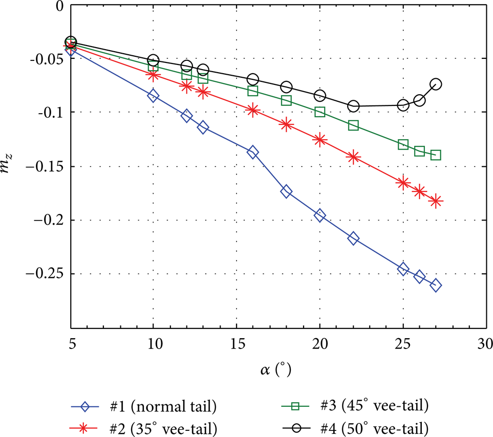
Comparison of the longitudinal moment coefficients for different tail types.
If the dihedral angle of the vee-tail is relatively small, the corresponding effective aspect ratio will become bigger. The effective balancing force will become greater. Then, the angle of installation will be reduced, and the “downwash” impacts created by the vortex in the downstream area will become smaller. As a result, the stalling limits can be largely delayed. On the contrary, if the dihedral angle of the vee-tail is too large, comparing with the smaller dihedral angle, the installed stealth height will be increased. Thus, the downwash region will be greater. As the AOA increases, the aircraft will begin to enter a serious deep stalling zone, losing the ability to maintain balance. This can have serious implications on the longitudinal stability of the whole aircraft.
As shown in Figure 8, the m z C l for the single fuselage is 2.17, and the m z C l for the wing together with fuselage configuration is 0.125, while the m z C l for the whole aircraft has changed to −0.135. The tail has contributed nearly 78% to the longitudinal stability. From this, we can see that the tail actually plays a vital role in the longitudinal characteristics. Choosing the suitable tail types can really satisfy the stability requirements of the whole aircraft.
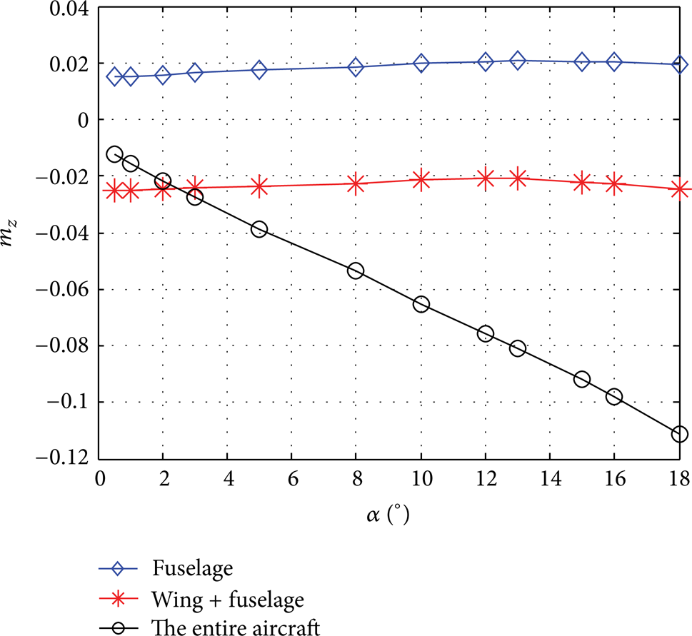
Comparison of the longitudinal moment coefficients for the single fuselage, wing together with fuselage, and the entire aircraft (#2 case).
3.3. The Yawing and Rolling Characteristics of the Vee-Tail Aircraft
There are mainly two major types of configurations: (i) wing without dihedral angle together with four kinds of tails and (ii) wing with dihedral angle (δ w = 3°) together with four kinds of tails. Combinations of AOA (5°) together with eleven kinds of angles of side-slip are used in the present study.
Figure 9 has shown the comparison curves of yawing and rolling moment characteristics for the two dihedral angle types of the wing. By comparing the wing without dihedral angle together with #1 tail and the wing with dihedral angle (δ w = 3°) together with #1 tail, we can see that, at certain side-slip angles, the dihedral angle can only contribute to the rolling moment and has no obvious effect on the yawing moment. Except this, in these two cases, the yawing moment of the whole aircraft tends to vary linearly with the side-slip angles.
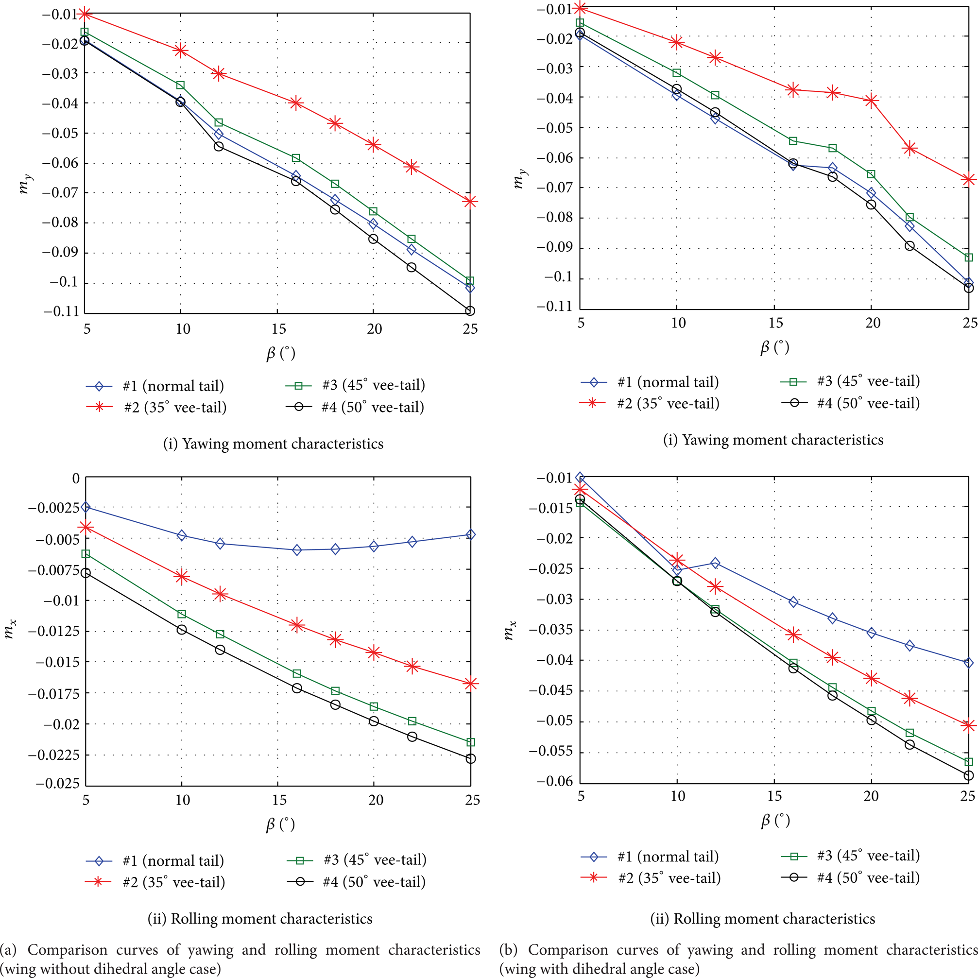
Comparison curves of yawing and rolling moment characteristics.
It is mainly due to the fact that the small dihedral angles can create a different resistance on the left and right wings during flight. It can make the contribution to the yawing moment of the whole aircraft. However, during the real flight, the wing is located much closer to the center of gravity of the aircraft comparing with the tail, so the yawing moment made by the wing with dihedral angles is quite small. As shown in Figure 10, whenβ > 0, for the left wing, the corresponding real AOA is α l = α + sinβ · sinδ w , while the right wing has become as follows: α r = α – sinβ · sinδ w , so the left wing has the bigger AOA, bigger lift, and bigger downwash than those of the right wing. The horizontal tail equipped with a single vertical tail is always positioned in the serious asymmetric downwash region created by the wing, which will not create the additional lateral forces. So the wing without dihedral angle together with #1 tail and the wing with dihedral angle (δ w = 3°) together with #1 tail are showing the same yawing moment.
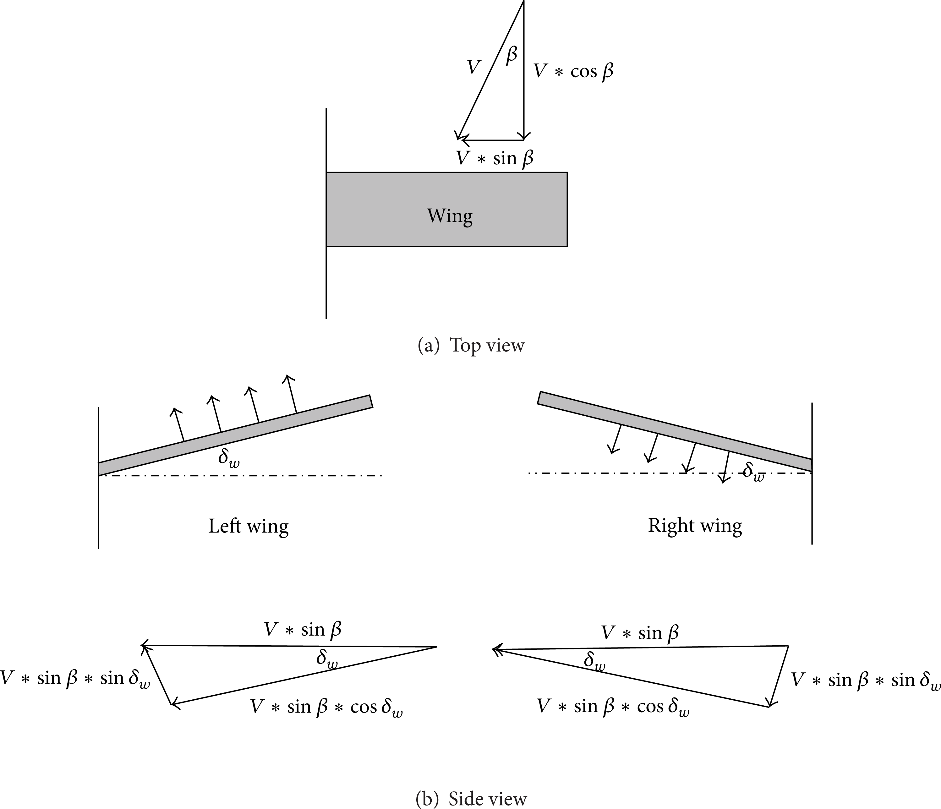
The additional angle of attack on the vee-tail created by the side-slip airflow.
As shown in Figure 9, if the wing (without dihedral angle) is added with vee-tail, it will make great contributions to either the yawing moment or the rolling moment. However, the corresponding yawing moments of the whole aircraft are still showing an incremental linear trend. If the wing (with dihedral angle) is added with vee-tail, the yawing moment will show an incremental nonlinear trend. It is mainly due to the fact that the vee-tail is in the serious asymmetric downwash created by the wing with dihedral angle, for the tail bending upward and the differential forces created by the right and left downwash effects; all of these factors can create a negative normal force on the right of the vee-tail and a positive normal force on the left of the vee-tail. Two forces combined together will provide an additional right lateral force for the entire vee-tail. And they can create an additional yaw moment Δm
y
in the center of gravity. But if
However, there are some limits on the size of the dihedral angle for the vee-tail. In general, the dihedral angle ranging between 20° and 45° should be more suitable. If the dihedral angle is too small, it will not have any influence. If it is too big, it will not only affect the longitudinal stability, but it can also make the recovery moment of lateral/directional direction too great, eventually making the aircraft have no power to manipulate the rudder in sliding. Even over the critical AOA, the aircraft would begin to rotate and enter the tail spin condition.
3.4. The Aerodynamic Characteristics for the Deflecting Aileron with Different Sizes
Throughout the configuration design of the whole aircraft, different sizes of aileron can directly affect various flying qualities of the aircraft. There are three different types of ailerons considered in the current study. They are narrow aileron (accounted 16% c), medium aileron (accounted 21% c), and wide aileron (accounted 42% c).
As shown in Figure 11(a), the lift coefficients for the three types of ailerons are decreasing with the increasing δ z . For the drag characteristics (Figure 11(b)), all the corresponding curves have experienced firstly a decreasing trend and then an increasing trend during the deflection. The drag for the narrow aileron will reach the minimum at about δ z = 25°, the medium aileron case is about δ z = 24°, and wide aileron case is about δ z = 17°.
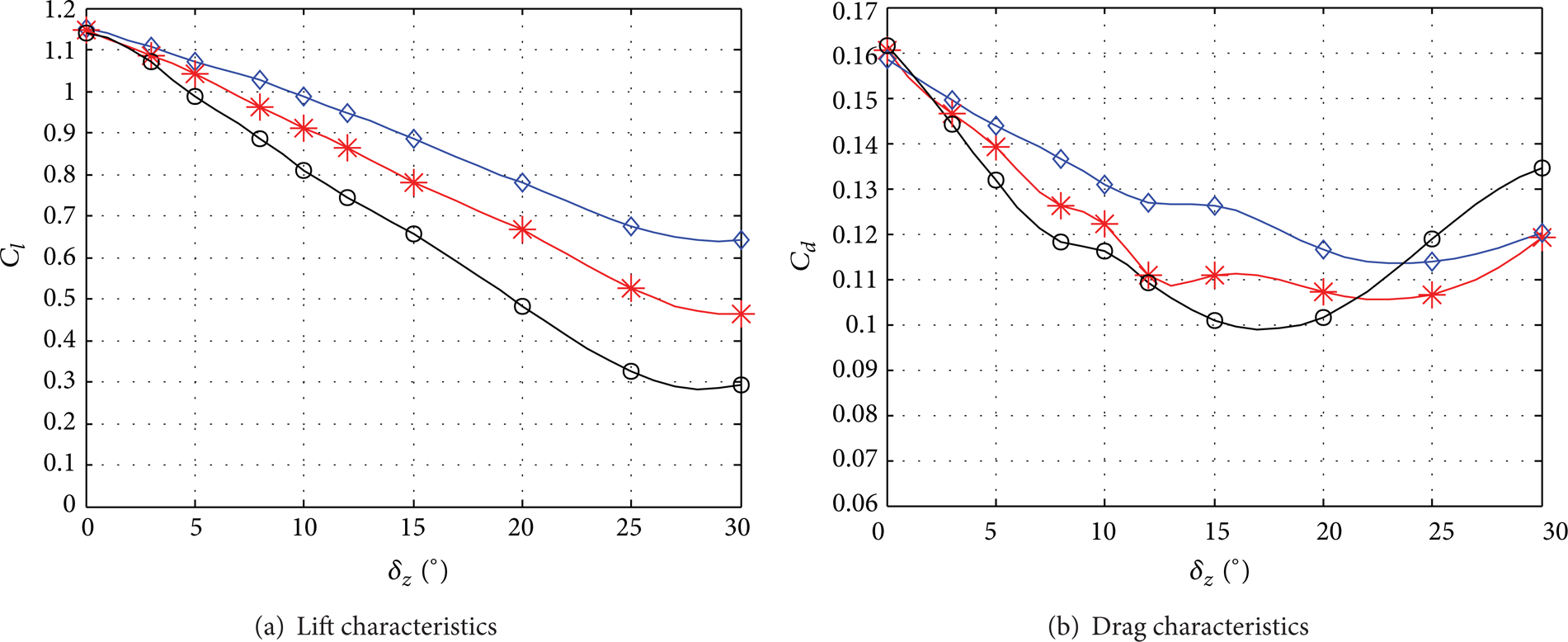
Comparison curves of the lift and drag characteristics for three different ailerons.
It is mainly due to the fact that, comparing with the wide aileron, the narrow rudder has relatively smaller effects on the aerodynamics of the whole wing. Prior to the aileron becomes parallel to the direction of airflow; the drag of the main wing is decreasing continuously. Due to the upward deflection motion, the aileron can make the pressure on the upper surface be greater than the lower surface. The differences can create a thrust forward force on the aileron. However, comparing with the wide aileron case, the narrow aileron had the weaker control ability on the flow of the main wing. When the aileron is paralleled to the direction of airflow (α = 5° at present), the drag of the wing will reach the minimum. Over the parallel critical position, the angle between the aileron and the airflow trends to increase, which makes the corresponding drag become larger. But the deflection of the wide aileron can directly affect the lift and drag characteristics of the entire main wing, so the curve is relatively steeper than the other two cases. It also indicates that reducing certain lift forces and maintaining a certain deflecting upward angle (δ z ) can effectively reduce the drag for the entire main wing.
In addition, the deflection of the aileron can also greatly affect the aerodynamics of the vee-tail because the vee-tail is located in the serious asymmetric downwash region created by the front wing. The bigger δ z becomes, the stronger asymmetry downwash effect will be generated. Except this, the wider the aileron becomes, the greater the domain and intensity of impact will become. So the deflection of aileron can strongly affect the stability. On the contrary, if the aileron becomes narrower, the corresponding manipulation sensitivity will be reduced and greatly affect the yaw efficiency of the aileron.
Figures 12 and 13 show the static pressure distributions on the upper surface of the wing and the section iso-surface of the wing (50% of aileron), respectively. From the above figures, we can clear see the effect of the pressure distributions on the wing created by the ailerons. Higher and lower pressure regions are distributed near the lower and upper surfaces of wing. The stagnation point can also be found at the leading edge of the wing. As shown in Figure 13, from the nonaileron to wide aileron cases, all the lower pressure regions on the upper surface of wing are moving gradually to the leading edge position while the higher pressure regions distributed on the lower surface of wing are moving gradually to the trailing edge position. Both of the corresponding pressure intensities are becoming weaker and weaker. Even for the wide aileron case, the corresponding high pressure region has almost disappeared (Figure 13(d)). These phenomena can also be found in Figure 14; as the aileron becomes wider, the regions between the higher and lower pressure curves are becoming smaller than the nonaileron case. Because the pressure differences are decreasing, the corresponding lift coefficients are also decreasing from the narrow to wide aileron.
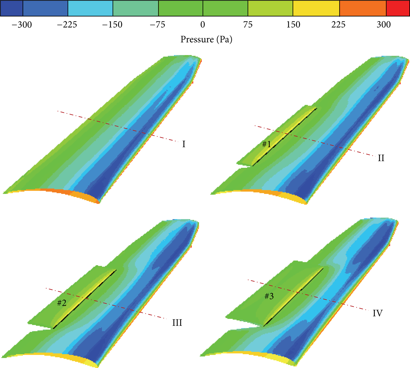
The static pressure distributions on the upper surface of the wing.

The static pressure distributions on the section of the wing (50% of aileron).

Plot of the pressure coefficients on the section of the wing (50% of aileron).
4. Conclusions
Whether the tails are normal or vee type, they have no obvious impacts on the C
lmax
and Cd0. However, they have a great impact on m
z
C
l
. The greater the span to chord ratio of the tail gets, the greater the longitudinal stability margin will become (m
z
C
l
∼ λ). If the dihedral angle of the vee-tail is too large, with the continuous increscent of AOA, the longitudinal moment curves will gradually move up. Even over a certain AOA, the curve will create a “loop”. The convoluting upward curve means that the longitudinal moment of the whole aircraft has not satisfied its own required balancing moment. This trend can directly destroy the flight stability of the whole aircraft. The vortices generated by the body head and wing can create a serious asymmetric downwash region near the layer of the tail. The causes of the longitudinal moment “loop” curve of the whole aircraft can be attributed to the downwash effect as well as the installing height of the vee-tail. Vee-tail can create an additional lateral force due to the serious asymmetric downwash effect created by the wing. This can create an unstable directional moment, which is contradicting to the directional stability contributed by the vee-tail. So the size of dihedral angle needs to be comprehensively considered. In general, the dihedral angle ranging between 20° and 45° should be more suitable. If the dihedral angle is too small, it will not have any influences. If it is too big, it will not only affect the longitudinal stability, but it can also make the recovery moment of lateral/directional direction too great, eventually making the aircraft have no power to manipulate the rudder in sliding. Even over the critical AOA, the aircraft would begin to rotate and enter the tail spin condition. Losing certain lift forces and maintaining a certain deflecting upward angle (δ
z
) can effectively reduce the drag for the entire main wing. From the nonaileron to wide aileron cases, all the lower and higher pressure regions on the upper and lower surfaces of wing are moving gradually to the leading and trailing edge positions, respectively. And the corresponding pressure intensity is also becoming weaker and weaker.
Footnotes
Nomenclature
Conflict of Interests
The authors declare that there is no conflict of interests regarding the publication of this paper.
Acknowledgments
Deepest gratitude goes first and foremost to Professor Yu, Professor Chien, and Professor Xu for their constant guidance. The authors also would like to thank the reviewers for their helpful suggestions.