
Abstract
The reasons to develop vehicle intelligent shift system were presented. A new vehicle intelligent shift system was developed, which included the shift subsystem of automatic transmission vehicle on the slope, on the low friction road, and in the turn situation. Also, the shift strategy based on the individual driving operation was developed. Furthermore, a hierarchical architecture of the developed intelligent shift system was proposed.
1. Introduction
There are many advantages to automate vehicle powertrain, such as the ease of driver's operation, prolonging powertrain's service life, and improving the vehicle fuel economy and emission, so the application of automatic transmission (AT) to vehicles has been continually increasing. Nowadays, the installation ratio of AT in the public cars has exceeded 90% in developed European Countries, and the ratio is 100% in the USA; the installation ratio of the AT in the top-grade passenger cars has exceeded 80% in Japan and is over 90% in the USA [1–3].
Although the conventional AT has been a mature product in the market, it determines the gear position solely on the vehicle speed and throttle opening and gives no consideration to the vehicle driving situations. Thus, although the conventional AT can work with satisfying performances in most situations, it can fall into troubles in some special situations, such as the shift hunting when a vehicle climbs a hill, the busy shifts when a vehicle is cornering, and the excessive slip when a vehicle travels on a low friction road. To overcome these problems, many different situation selection switches and the range gear positions, such as “D, D2, and D3,” are added to the conventional AT, which cannot only add the driver's operation burden but also enhance the requirements to the driver's operation skills. Furthermore, if a driver cannot manipulate the selection switches correctly or put the shift lever in a proper position, the AT will not work successfully. On the other hand, it is impossible to meet thousands upon thousands of drivers' desires with an identical shift schedule. How to make the AT a significant value in terms of the driving feelings and expectations? It is the vehicle intelligent shift system (VISS) that is aimed at solving these problems. The VISS promises to be the developing trend of future automatic transmissions [4–22].
In recent years, the main carmakers all over the world have begun to research and develop the vehicle intelligent AT [23–32]. Many methods have been employed in developing the intelligent AT, among which the statistical analysis [30], fuzzy inference [31], and artificial neural networks [32] are of the most importance.
To develop new generation advanced AT with excellent performances, our researches focus on improving the driving performances of the AT vehicle on the slope, on the low friction road, and in the turn situation and make the AT vehicle have the ability to change its shift schedules with individual driver's operation. Furthermore, a hierarchical architecture of the intelligent shift system is proposed.
2. The Slope Intelligent Shift System
2.1. The Reasons to Develop a Slope Shift System
When a vehicle travels on a slope, the gears cannot shift properly. For example, when a vehicle travels on an uphill, the busy shifts can occur, which cannot only degrade the ride comfort of the vehicle but also have negative effection on the lifespan of the powertrain components; when a vehicle travels on a downhill, the gear position and vehicle speed are likely to continuously increase, so that the driver has to frequently depress the brake pedal to decelerate, which will add driver's operating burden. Moreover, if the downhill is long, continuous use of brakes may cause the brake to overheat and fail, which is very dangerous for the vehicle.
2.2. The Method to Identify the Slope Grade
The vehicle longitudinal acceleration can be described as
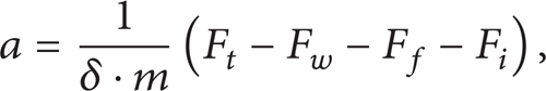
where m is the mass of the vehicle, δ is the correction coefficient of the rotating mass, F t is the tractive effort, F w is the aerodynamic resistance, F f is the rolling resistance, and F i is the grade resistance.
We can know that the vehicle acceleration rate can be determined only by the road slope angle at a given throttle opening and vehicle speed [4]. So, a reference table can be established denoting vehicle acceleration rates at different vehicle speeds and throttle openings. By comparing the detected vehicle acceleration rate with the acceleration rates listed in the table, the current road gradient can be identified.
Roads, on which vehicles usually travel, can be divided into seven types: steep uphill, moderate uphill, gentle uphill, level, gentle downhill, moderate downhill, and steep downhill. Therefore, if five different reference tables are established denoting the relationship of vehicle acceleration rates to vehicle speeds and throttle openings, the different road types can be identified.
2.3. Implementation of the Slope Shift System
After getting the road types, the proper shift schedule corresponding to the road gradient can be adopted so as to achieve good vehicle driving performances. The following are the steps to obtain the proper upslope shift schedule according to the vehicle's sensor signals.
Determine whether the gearshift is going on according to the detected clutch displacements. If the gearshift is going on, T0 seconds should be delayed. Otherwise, go to the next step.
Detect current vehicle speed and the throttle opening.
If the change rate of the throttle opening is greater than the preset value, T1 seconds should be delayed. Otherwise, calculate the vehicle acceleration.
Determine whether the vehicle is traveling on the level road according to the level road look-up table. If it is so, the level road shift schedule should be adopted. Otherwise, determine the vehicle is traveling on the uphill or on the downhill.
If the vehicle is traveling on the uphill, determine whether the steep uphill, moderate uphill or gentle uphill, the vehicle is traveling on according to different look-up tables. Then, the level road shift schedule should be modified according to current road gradient, and the modified shift schedule will be adopted as current shift schedule, which can overcome the problems aforesaid. The method to obtain the proper downslope shift schedule is similar to this.
2.4. Slope Shift Schedules Design
Slope shift schedules design includes uphill shift schedule design and downhill shift schedule design.
2.4.1. Uphill Shift Schedule Design
Figure 1 illustrates a correction method to obtain different slope shift schedules based on the level road shift schedule.

Shift schedules on different uphill gradients. Line 1 is the shift schedule on the level road, 2 is on the gentle uphill, and 3 is on the steep uphill.
The correction value ΔV in Figure 1 can be described as

So, the upshift speed on a slope with the slope angle θ and at the throttle opening α can be described as

where f0 (α) is the upshift speed when a vehicle travels on a level road with the throttle opening α. An upshift will only be performed when the current vehicle speed is greater than V s .
2.4.2. Downhill Shift Schedule Design
If a driver feels that the current gear position is too low, he can increase the throttle opening. In this case, the shift lines need to move towards the left to meet the driver's demands, which mean shortening the range of the lower gear positions. If the driver feels that the current gear position is too high, he can increase the brake force. In this case, the shift lines need to move towards the right to broaden the range of the lower gear positions.
Figure 2 shows the method to shorten and broaden the range of lower gear positions dynamically. After the range has been adjusted several times, the shift lines will satisfy the driver's expectation.

A method to broaden and shorten the range of lower gear positions.
2.5. Simulations and Field Tests
Figure 3 shows the results of a field test for a conventional AT vehicle traveling on a slope at a constant throttle opening. The test road was a long steep downhill slope followed by a long steep uphill slope. The figure shows that when the vehicle traveled downhill, because the tractive effort was greater than the running resistance, the vehicle speed and gear position both increased continuously; when the vehicle traveled uphill, the vehicle speed and gear position both decreased continuously. This proved that when a vehicle travels downhill, it cannot remain in a lower gear position to make the vehicle decrease by utilizing the engine's brake capacity.

Field test results of a conventional AT vehicle traveling on the steep downhill and uphill slope.
Figure 4(a) shows the simulation results of shift hunting when a vehicle travels uphill. In the simulation, the throttle opening was initially set at 67%, and then at 15 seconds a 10% uphill gradient input was added, and the throttle opening remained constant all the time. Figure 4(b) shows the simulation results with the same conditions as in Figure 4(a), except that the shift strategy was changed; the busy shifts were eliminated in Figure 4(b). A comparison of Figures 4(a) and 4(b) reveals that when a vehicle travels uphill, busy shifts can be eliminated by modifying the conventional shift schedules.

(a) The simulation results of vehicle speed and gear position continuously increase on the downslope. (b) The simulation results of vehicle speed and gear position keep the same on the downslope.
3. The AT Vehicle Control on the Low Friction Road
3.1. The Reasons to Develop This System
When the conventional AT vehicle travels on the low friction road, the excessive slip can occur; this has a negative effect on the vehicle performances. Although the ready-made antislip system can achieve good performances, it is very expensive. As a result, its application is limited especially in the ordinary cars. In fact, if the antislip system based on the engine torque regulation can be attached to the conventional AT vehicle, the vehicle's tractive performance, handling performance, and driving stability on the low friction road will all be improved with very low additional hardware costs. Therefore, this system has very good prospects in the compact cars.
3.2. The Method to Identify the Road Friction
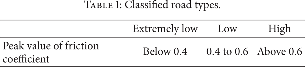
Friction coefficient of different road surfaces varies greatly. Generally, by identifying just a few kinds of road surface conditions (dry, wet, or slippery, etc.), either ABS or ASR can obtain the range of ideal slip rate and achieve favorable control performances, and there is no need for more precise identification. Therefore, the method for identifying road surface friction based on the deceleration of driving wheel will be introduced here. The friction coefficients of different road surfaces can be classified into three categories, namely, extremely low, low, and high. Refer to Table 1 for clarification of road surfaces.
Classified road types.
The angular speeds measured by four-wheel speed sensors located at front left, front right, rear left, and real right are, respectively, represented by ωfl, ωfr, ωrl, and ωrr, and when taking R as wheel radius, the slip rate of driving wheels for front-wheel-drive vehicles can be defined as follows:

In the previous formula,

With the angular speeds of the four wheels measured in real time during running, the slip rate of the driving wheels can be obtained through formula (4). When the measured slip rate is bigger than a predetermined value (such as 15%) saved in electronic control unit, the electronic control unit will consider that the driving wheels are experiencing relatively large slip and will instruct to close the throttle opening and hold it for a while to eliminate excessive slip. When the throttle opening is reduced, speed of the driving wheels will decline quickly.
Figure 5 is the variation of angular speed of driving wheels when the throttle opening is closed.

Variation of speed of the driving wheels.
If we use ΔT to represent the time interval between point b and point c, the deceleration of driving wheels during ΔT can be calculated as

By mechanics analysis of driving wheels during running, it can be deduced that deceleration of driving wheels is determined by the friction conditions between tires and road surfaces. Friction conditions of current road surface, therefore, can be deduced from the deceleration value of driving wheels. According to test results, when excessive slip occurs on driving wheels, the obtained deceleration of driving wheels by closing throttle opening distinctively varies on road surfaces of different frictions; therefore, the attempt to obtain the friction conditions of current road surface through deceleration of driving wheels after the throttle opening is closed is feasible.
3.3. The Implementation of This System
The road friction recognition method based on the drive wheels' deceleration is investigated, and a fuzzy antislip control system with the engine torque regulation is developed. In this system, the vehicle's target speed is determined according to current road friction. The fuzzy inference rules and the engine control modes are designed based on the deviation and its change rate between the vehicle's target speed and the actual speed. Figure 6 shows the antislip fuzzy controller structure of our AT vehicle.

The antislip fuzzy controller of our AT vehicle.
3.4. Experiments and Analysis
Figure 7 is the process of variation in the driving wheel speed and driven wheel speed during the elimination of slip through throttle openings control. Figure 7 has clearly shown the process of variation in the driving-wheel speed and driven wheel speed during the excessive slip process (0∼16 sec.), slip elimination process (16∼21 sec.), and the process of normal running without slip (21∼32 sec.) It can be deduced that excessive slip of driving wheels can be eliminated by appropriately adjusting and controlling engine throttle openings, when the vehicle travels on the wet and slippery road surface. Thus, running performances of the vehicle under wet and slippery road conditions can be improved.

The process of variation in the driving wheel speed and driven wheel speed during the elimination of slip through controls over throttle openings. The solid lines are the left and right driving wheel speeds, respectively, and the broken line is the mean speed of the driven wheels.
4. The AT Vehicle Control in the Turn Situation
The control of AT vehicle in the turn situation is very complicated. Not only vehicle's optimal gear position determined by the overall vehicle performances needs to consider but also the vehicle's autonomous control needs to execute if the vehicle will lose stability due to the driver's mistaken operation. A method to deduce the driver's deceleration intentions in the turn situation is proposed, and a vehicle dynamic stability control system based on the speed error between the left driven wheel and the right driven wheel is developed. Also, a method to predict the turn situation is proposed. The proposed system can achieve good vehicle driving performances in the turn situation with very low additional hardware costs. Figure 8 is the principle diagram of vehicle dynamic stability control, and Figure 9 is the synthetical control method when the AT vehicle travels in the turn situation.

The principle diagram of vehicle dynamic stability control.

The synthetical control method of the AT vehicle in the turn situation.
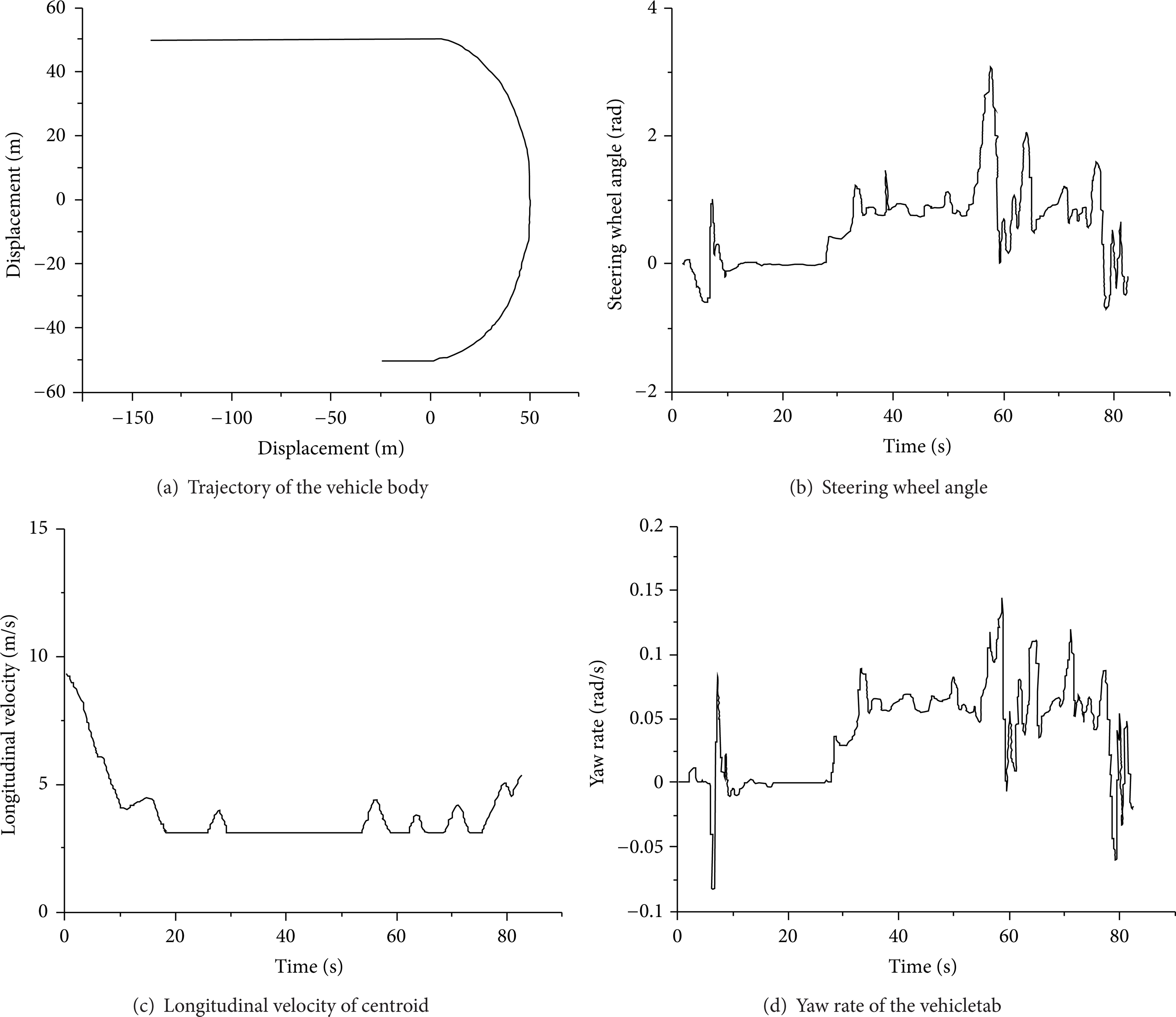
Figures 10 and 11, respectively, show the test curve of sideslip when a vehicle corners on a road with a slip adhesion coefficient of 0.1 and the test curve of sideslip elimination through speed control in the driving simulator in Jilin University, which is the largest one in China.

Vehicle cornering with the sideslip.
Vehicle cornering while eliminating the sideslip.
As is implicated in Figures 10 and 11, speed control already can enable the vehicle to complete cornering smoothly under extremely low road adhesion conditions. However, we see big fluctuation in the steering wheel angle and yaw rate during the cornering to keep the vehicle moving along the anticipated locus, which indicates that cornering is actually very hard to control when the vehicle moves a road of such a low adhesion, and destabilization easily happens.
5. The Shift Strategy Based on Individual Driving Operation
To improve the adaptation of the conventional AT to different drivers, a new shift schedule method based on driving style inference is proposed. The driving style coefficient in the optimum fuel economy condition is defined as 0, and the driving style coefficient in the optimum dynamical characteristic condition is defined as 1. So, the arbitrary driving style coefficient is a real number between 0 and 1. A two-input, single-output fuzzy system to infer the driver's driving style coefficient is established. The two inputs are the change rate of the accelerator pedal displacements and the average deceleration when the vehicle brakes and the output of the fuzzy system is the driving style coefficient, which represents different driving styles. The shift schedule based on driving style inference is developed according to the shift schedule in the optimum fuel economy condition, the shift schedule in the optimum dynamical characteristic condition, and the inferred driving style coefficient. Also, the shift plain is divided into different shift areas according to the vehicle performances, and the corresponding interpolation functions in different shift areas are proposed. Figure 12 is the computed shift schedule when the inferred driving style equals 0.5.
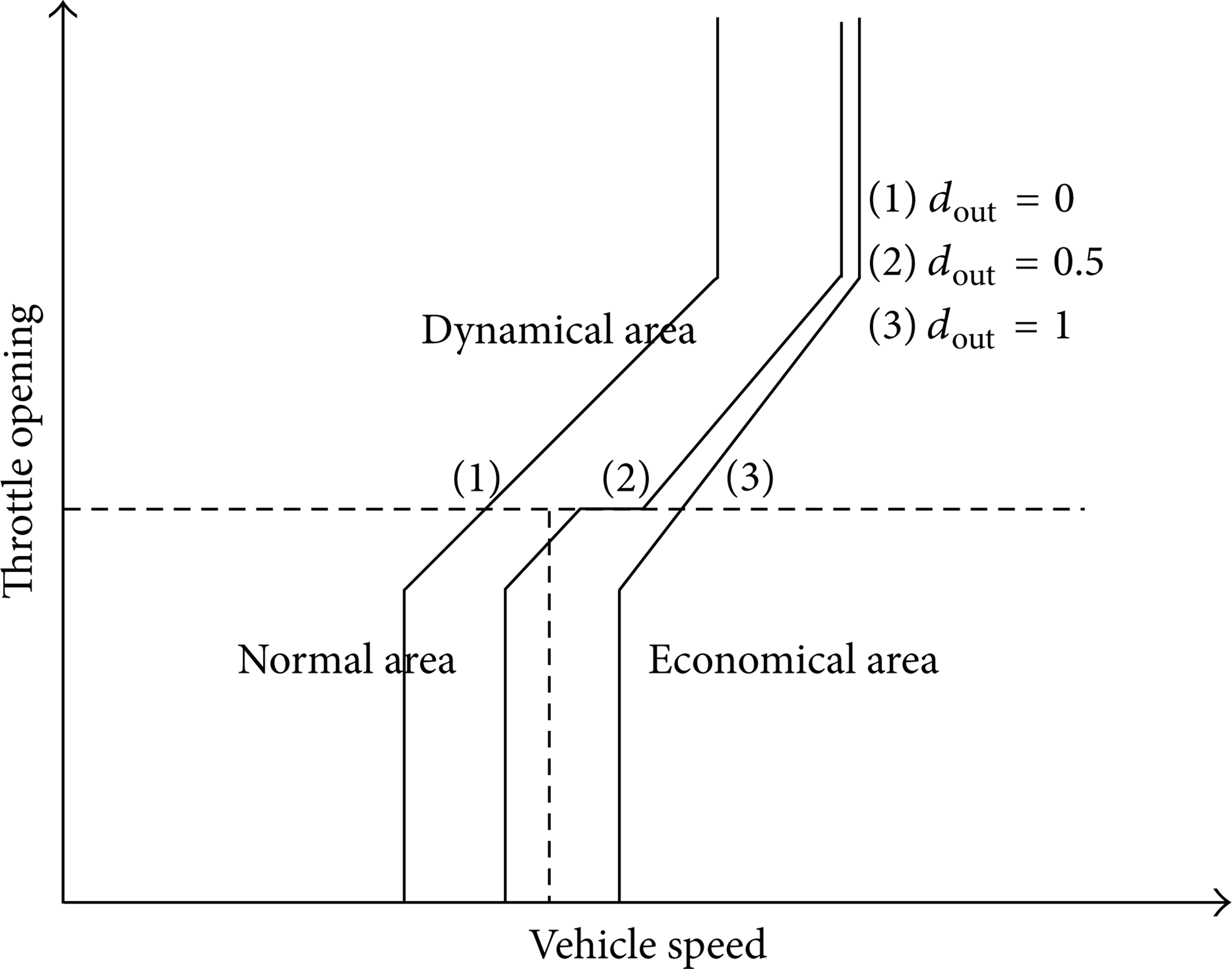
The shift schedule of driving style equaling 0.5.
6. The Hierarchical Architecture of Developed Intelligent Shift System
To coordinate all the information coming from the slope, road friction, curvature, and driving style identifiers and to make a reasonable global decision, a two-level real-time hierarchical architecture of developed intelligent shift system is proposed.
In Figure 13, what in the dotted line is the lower level recognition system, which consists of four parallel identifiers to recognize different driving styles, road frictions, slope gradients, and turn situations. When a vehicle travels, the four identifiers can make real-time parallel recognition according to the vehicle's sensor signals. The upper level of the system accepts the recognition results from the lower level and makes inference and decision based on the preset rules. The outputs of the upper level are used to control the vehicle behaviors.

The hierarchical architecture of the intelligent shift system.
7. Conclusion
Although many vehicles with intelligent AT functions have been in the market, the task to develop intelligent AT with excellent performances is still arduous. Firstly, the performances of current commercial available system need to improve. The current such systems' ability to identify different driving situations is not powerful, and the adaptation to different drivers cannot meet different kinds of drivers' demands, and so forth. Furthermore, new intelligent functions need to be added. The intelligent AT is an open system, what have been achieved in the research can be applied immediately in vehicles, which will not only reduce the driver's operation burden but also improve the vehicle driving performances to a large degree.
In this paper, the reasons to develop the intelligent AT are analyzed. Our researches in the vehicle intelligent AT are systematically illustrated from the slope shift system, the AT vehicle control on the low friction road, AT vehicle control in the turn situation, and shift strategy design based on individual driving style inference. Also, a hierarchical architecture of intelligent shift system is proposed. The methods and technologies illustrated can make contributions to the vehicle intelligent AT system in a creative way and is valuable to improve the performances of conventional AT vehicle with a very low additional hardware costs. Furthermore, these methods and technologies are significant to other new generation vehicle electronically controlled systems (such as the electric power steering, shock absorbers) aiming at achieving excellent performances in some specific driving environments.