
Abstract
Pultrusion is a continuous manufacturing process used to produce high strength composite profiles with constant cross section. The mutual interactions between heat transfer, resin flow and cure reaction, variation in the material properties, and stress/distortion evolutions strongly affect the process dynamics together with the mechanical properties and the geometrical precision of the final product. In the present work, pultrusion process simulations are performed for a unidirectional (UD) graphite/epoxy composite rod including several processing physics, such as fluid flow, heat transfer, chemical reaction, and solid mechanics. The pressure increase and the resin flow at the tapered inlet of the die are calculated by means of a computational fluid dynamics (CFD) finite volume model. Several models, based on different homogenization levels and solution schemes, are proposed and compared for the evaluation of the temperature and the degree of cure distributions inside the heating die and at the postdie region. The transient stresses, distortions, and pull force are predicted using a sequentially coupled three-dimensional (3D) thermochemical analysis together with a 2D plane strain mechanical analysis using the finite element method and compared with results obtained from a semianalytical approach.
1. Introduction
Pultrusion is a continuous manufacturing process used to realize constant cross sectional composite profiles. In recent years, the pultrusion process experienced a remarkable growing within the composite industry, due to its cost-effectiveness, automation, and high quality of products. Nowadays, the process is widely used to manufacture highly strengthened structures such as wind turbine blades, window profiles, door panels, and reinforcing bars for concrete. Moreover, in some applicative sectors, such as in the automotive industry, the environmental impact of pultruded composite structures over the entire life cycles results is lower than other engineering materials [1]. A schematic view of the pultrusion process is depicted in Figure 1. During the process, the reinforcement fibers, in the form of rovings or mat, are pulled through guiders and impregnated by the resin material in an open bath or employing a resin injection chamber. Wetted out reinforcements are then pulled via a pulling mechanism through the heating die. The die inlet is typically characterized by a tapered or a conical convergent shape, in order to promote the desired impregnation and compaction of the reinforcement, the removal of the air and the excess resin. In the straight portion of the die, the heat provided by means of electrical heaters or hot oil activates the exothermic cure reaction of the thermoset resin. As a consequence, the material changes its status from reactive liquid to gel and then vitrified solid [2, 3]. The thermochemical behavior of the processing thermoset resin, generally represented by time-temperature-transformation (TTT) diagrams [2–4], is a crucial issue. During the curing process, the resin shrinks because of the chemical reaction (cross linking) promoting the contraction of the work piece. Besides that, the part continues contracting due to the cooling effect, for example, convective cooling at the postdie region. At the end of the process, the cured and solidified product is cut into desired lengths.

Schematic view of the pultrusion domain for the composite rod.
Even if the process is conceptually quite simple, the analysis of its dynamics and the definition of optimal processing parameters are a complex task, due to the mutual interactions between involved physical phenomena, mainly related to heat transfer, species conversion and phase changes, die-material contact, and stress-strain development. Several researchers have performed numerical and experimental investigations on different aspects inherent to the pultrusion process, mainly focusing on issues related to heat transfer and cure [5–11], pressure distribution [12, 13], and pulling force [14–20]. However, proposed models often neglect the interactions between involved phenomena, on the base of some simplifying assumptions. Most of the published works converge on the conclusion that the mechanical properties and the quality of the pultruded composite are strongly affected by the degree of cure (DOC) distribution and the applied pulling force. The aforementioned features, in turn, depend on the pull speed, die temperature, die geometry, constituents' type, and volume fractions. Furthermore, the pulling force consists of different contributions, such as the bulk compaction force due to the pressure increase in the tapered portion of the die, the viscous drag acting in the liquid zone, and the frictional force due to the contact between the internal surface of the die and the solidified processing material [2, 3, 18–21]. Experimental outcomes reported in [14] by Price and Cupschalk showed the impact of the materials volume fractions, die temperature and pull speed on the pull force. It was also indicated that for a constant temperature, and pulling speed, the force increases exponentially with the volume of material. Lackey and Vaughan carried on an extensive experimental and statistical investigation on the influence of process parameters on the pulling force and flexural strength of pultruded products, employing a five-factor half-factorial central composite design (CCD). It was concluded that the process parameters affect the pulling force according to complex interactions whose overall effect may vary significantly using resin systems characterized by different cure kinetics [15]. Considering the elevated number of variables involved in the aforementioned problem, a satisfactory experimental analysis could result in undesired time and money spending. Furthermore, pure experimental tests may have no solid predictive capability. As a consequence, the development of suitable multiphysics models is highly required for composite manufacturing processes. In-plane stresses and deformations in composite laminates can also be related to the interaction between the tool and the part [22]. Besides, the temperature and the DOC gradients through the composite thickness also promote the development of residual stresses in the manufactured part [23]. A better understanding of these phenomena, which take place in the heating die as well as in the postdie region, is highly required to reduce process induced shape distortions and residual stresses and to obtain a realistic analysis of inservice loading scenarios and reliability assessments [24, 25]. It should be noted that the general mechanical behavior of the composite material is orthotropic (transversely isotropic if only unidirectional fibers are used) and the coefficient of thermal expansion (CTE) of the polymer-matrix materials is usually much higher than that of the fibers. Hence, dimensional variations and internal stresses are induced mainly due to the curing shrinkage of resin and the mismatch in the CTE of the fibers and the resin matrix [26].
In the present work, several processing models dealing with different phenomena are combined to simulate the manufacturing of a pultruded product. This approach has not been considered up to now for the analysis of the pultrusion, providing a better understanding of the entire process at a glance. A schematic representation of the implemented models, including outputs and relative connections, is depicted in Figure 2.
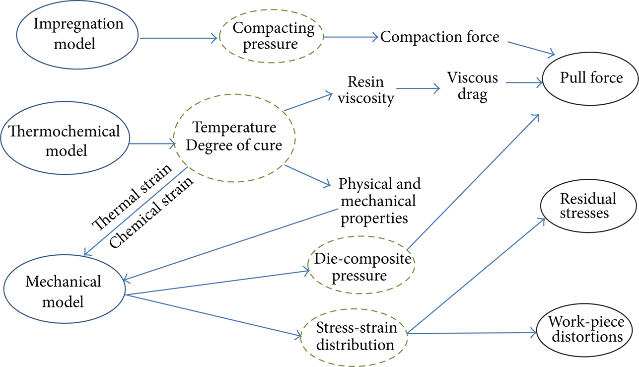
Implemented models and coupling effects in pultrusion.
In particular, pultrusion process simulations are performed for a unidirectional (UD) graphite/epoxy composite rod including different processing physics with the aim to predict the pulling force and the stress/distortion evolutions in the processing material. All the contributions to the overall pulling force have been accounted for in the present work. The pressure increase, which is responsible for the bulk compaction force, has been derived by means of a computational fluid dynamics (CFD) model of the resin flow field at the inlet and solved using a finite volume (FV) approach. The reinforcing fibers have been modeled as an anisotropic porous media, with directional permeability in accordance with the Gebart model. The temperature and the DOC distributions inside the heating die and at the postdie region are obtained by means of a three-dimensional (3D) thermochemical analysis. Two different modeling approaches are implemented: a continuous finite element (FE) model and a porous FV model, based on different homogenization levels and solution schemes. Both models provide the viscosity field allowing one to infer the viscous drag acting in the liquid zone. Furthermore, two solution strategies have been developed and compared for the prediction of the normal pressure, which generates the frictional force, between the processing material and the internal die surface after resin gelation. In the first case, numerical outcomes provided by the FV porous model have been analytically processed considering the well-established relations of the continuous mechanics, resulting in a semianalytical method (SAM). In the second approach, the transient stresses, distortions, and frictional pull force are predicted using a sequentially coupled 3D thermochemical analysis together with a 2D plane strain mechanical analysis using the finite element method (FEM). In both cases the evolution of the mechanical properties of the processing material is computed using the cure hardening instantaneous linear elastic (CHILE) approach [25, 27]. The paper is organized as follows: in Section 2 the theoretical modeling and the governing equations are described in detail, while in Section 3 the obtained results are exposed and discussed. Finally, in Section 4, the relevant findings and the future perspectives of this research are highlighted.
2. Theoretical Modeling and Numerical Implementation
2.1. Pull Force Model
As aforementioned, four different contributions to the overall pulling force in pultrusion have been identified in the literature [2, 3, 14–21]: the collimation force Fcol, the bulk compaction force Fbulk, the viscous drag Fvis, and the frictional force Ffric. These contributions are strictly related to the geometrical features of the die-work piece system and to the resin transitions from liquid to gel and then solid status, as schematized in Figure 3.
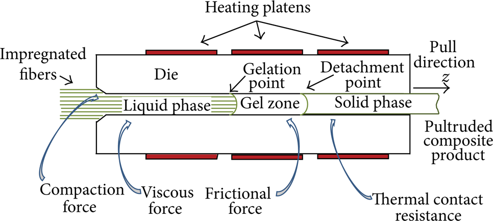
Phase changes and force contributions in pultrusion.
The first contribution Fcol is due to resistances arising from the creel to the die inlet and it is generally assumed to be negligible. As a consequence, the pulling force Fpul can be expressed as follows:

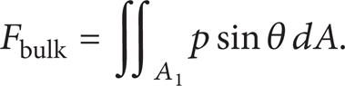
Fbulk is related to the increase in the resin pressure typically observed in the initial part of the die, that is, when the resin is still in liquid phase. The die inlet is generally designed as tapered (θ ≤ 10°) or rounded shapes [4] in order to promote the constituents compaction reducing fibers damage. Moreover, the resulting over-pressure allows the resin to completely fill the reinforcing material porosities. At the same time, this overpressure forces the excess resin to flow back, as depicted in Figure 4. The excess resin is usually recovered and redriven to the open bath for the fiber impregnation. While the resin is in a liquid status at the die entrance, the force due to the applied pressure acts along a direction normal to the die surfaces. As a consequence, it does not affect the pulling force except at the tapered die entrance (Figure 4). Defining the local resin pressure as p, the die taper angle as θ, and the inlet surface as A1, the bulk compaction term can be written as follows:

Resin flow and pressure increase at the die inlet.
In the straight portion of the die, the increase in the temperature of the processing resin, due to the heat provided by the heaters, activates the exothermic cure reaction. The crosslinking of the thermoset monomers, in conjunction with the existing temperature field, provides two relevant phenomena, namely, gelation and vitrification, in which the status of the resin is changed. The term gelation refers to the transition of the catalyzed resin from viscous liquid to gelled (rubbery) solid. This transition is associated with the achievement of a certain degree of cure or polymerization (degree of cure at gelation, αgel), which corresponds also to a sharp increase of the resin viscosity. Vitrification (glass transition) is not rigorously associated with a specific extent of the cure reaction, but with the (α-dependent) glass transition temperature (T g ). If the resin temperature is below T g , it behaves as a vitrified (glassy) solid. Differently from gelation, vitrification is a reversible phase change.
Before the gel point, viscous drag occurs at the die wall. This resistance is imputable to the presence of a thin liquid layer between the travelling fibers and the stationary die surface. Thus, a plane Couette flow is induced, in which the reinforcing fibers are assumed to be the moving plate translated at a constant pull speed and the die surface as the fixed plate. A schematic view is shown in Figure 5 [17]. The viscous force can be written analytically as follows:

where λ is the thickness of the resin layer between the solid boundary and the moving fibers, η denotes the resin viscosity, vpul is the fiber pull speed, and A2 is the surface interested by viscous effects, whose length is determined by the gel-point. Several approaches for the estimation of λ have been adopted in the literature, mainly based on the fiber packing, the radius r f , the volume fraction v f , or permeability considerations [16, 17]. In the present investigation, the following relation has been employed [17]:
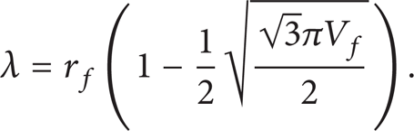
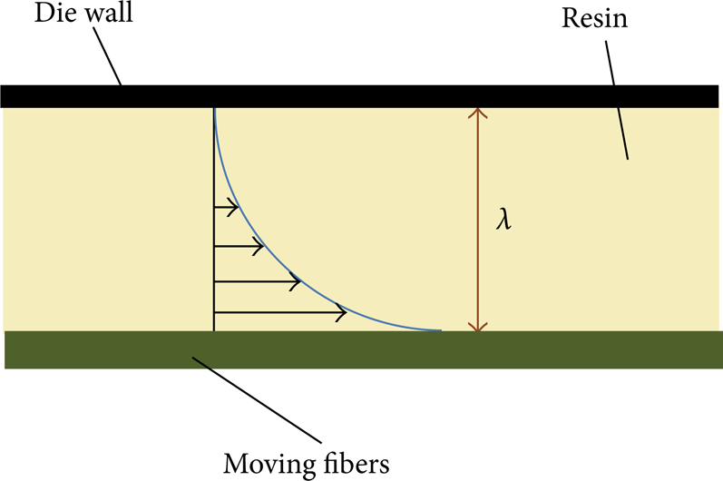
Couette flow in the liquid region.
The rheological behavior is herein modeled following the well-recognized three parameters correlation model [12, 13, 16, 17], which is expressed as follows:

where R is the gas constant, T is the absolute temperature, η∞, ΔEη and K are material parameters provided by experimental data fitting.
After the gel point, the resin flow and the viscous effects are obviously inhibited and the composite is mechanically pulled through the die. Consequently, the interaction between the processing material and the die surface is mainly characterized by frictional effects. Generally, the entity of the frictional force can be inferred by considering the friction coefficient μ and the contact pressure σ, according to the following equation:

being A3 the die surface from the gel-point to the detachment point. It should be noted that the value of the friction coefficient depends on the DOC during the resin gelation and further varies at the glass transition. However, due to the lack of thorough experimental data, generally the averaged values are utilized [14–21]. Regarding the magnitude of the contact pressure, σ is considered to be affected by two contrasting conditions: the transverse thermal expansion of the composite due to the increase in temperature and pressure and the resin chemical shrinkage related to crosslinking reaction. The latter phenomenon leads to a progressive reduction in the size of the composite cross section until it shrinks away from the die internal wall (detachment point).
It is worth noting that the separation of the processing material from the die cavity induces the formation of a thin (thermally insulating) air layer. As a consequence, a thermal contact resistance (TCR) is interposed between the heated die and the processing material. In the present investigation, each contribution has been computed using the numerical and the semianalytical models, as explained in detail in the following.
2.2. Impregnation Analysis
In a conventional pultrusion process, reinforcing fibers are wetted out inside the resin bath before entering the heating die. After the impregnation, the wetted fibers typically show an excess of resin with respect to the amount needed for the final product. As a consequence, in the tapered zone of the die (inlet) the processing material is compacted resulting in a pressure increase with respect to the atmospheric value. Material compaction is affected by several factors, such as the volume fraction and the permeability of the reinforcement, the resin viscosity, and the geometrical features of the die-material system [12]. The impregnation model describes the pressure distribution and the resin flow in the first part of the die, including the tapered or rounded zone and a portion of the straight die (Figure 4). Velocity and pressure in the reinforcement-free zones of the domain are inferred by means of the conjunct solution of the well-known mass and momentum equations. In particular, since the early part of the die is not heated in order to avoid premature resin gelation, it is assumed that the temperature and the DOC variations are negligible, and therefore the resin viscosity remains constant. Furthermore, under the hypothesis of incompressibility of the liquid resin and neglecting body forces, the equilibrium equations can be written as follows:

where u, v, and w are the velocity components of the resin along the x, y, and z directions, respectively, and p is the liquid pressure. The reinforcing fibers have been treated as a moving porous media, in which the porosity and the permeability vary according to geometrical considerations, ensuring always the final fiber volume. The following modified Darcy model has been solved in the porous region:

where U, V, and W represent the velocity components of the porous media along the x, y, and z directions, respectively. It should be noted that, assuming that z-direction is the pull direction, the component W is constant and it is the only nonzero term in the straight portions of the domain, while other components should be locally modified considering the geometric configuration of the tapered zone [12]. Tow permeability has been defined according to the Gebart model as follows:

where r f is the fiber radius, Vf, max the maximum achievable fiber volume fraction, C1 and c are constants equal to 0.231 and 53, respectively [13]. The impregnation model has been implemented and solved using a FV scheme. The commercial software ANSYS-CFX has been employed for this purpose. The pressure distribution provided by the impregnation model is then used in (2) to evaluate Fbulk.
2.3. Thermochemical Analysis
In this section, theoretical backgrounds of the implemented continuous and porous models are presented.
2.3.1. Continuous Model
The basic assumption of the continuous (homogenized) model is that in each location of the processing composite material, all the constituents experience the same temperature. As a consequence, the whole temperature field is established solving a unique nonlinear equation using the lumped material properties [4–11, 16–18], which can be written as follows:
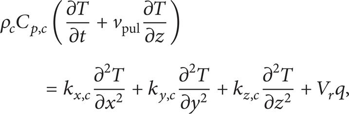
where T is the temperature, t is the time, ρ c is the density, Cp, c is the specific heat, kx, c, ky, c, and kz, c are the thermal conductivities of the composite material along x, y, and z directions, respectively, and V r is the resin volume fraction. Material properties are assumed to be constant throughout the process. The source term q in (10) is related to the internal heat generation due to the exothermic resin reaction and is expressed as follows:

where R r is the reaction rate, H tr is the total heat of reaction, and ρ r is the resin density.
Several kinetic models have been proposed and discussed in the inherent literature to describe the evolution of the cure reaction. In the present investigation the well-established nth-order model has been adopted, assuming an Arrhenius type dependence on the absolute temperature:

where α is the degree of cure and H(t) is the heat generated during cure. The above equations have been solved in a 3D domain using a FE approach. The evaluation of the DOC and the reaction rate has been obtained by means of an iterative inhouse developed routine implemented into the commercial software package ABAQUS [28], until the matching of temperature and DOC tolerances to reach the steady state. The DOC is obtained by using the following discretization [7, 25]:

2.3.2. Porous Model
Differently from the continuous model, the porous model treats the pultrusion process as a reactive liquid (resin) flow through a moving porous media (reinforcement) inside a defined rigid boundary (die cavity). In other words, it is a CFD based nonthermal equilibrium model considering each component as a different entity on macroscale; therefore a finite difference between the reinforcement and the matrix temperatures is admitted. As a consequence, besides the continuity and the momentum equations for the fluid phase, one energy balance equation for each component is needed. This allows heat to be transferred between contiguous phases. Assuming that the processing composite is only composed by the reacting resin and the fibrous reinforcement, that is, neglecting voids and porosity effects, the temperature field can be obtained by solving the following equations:

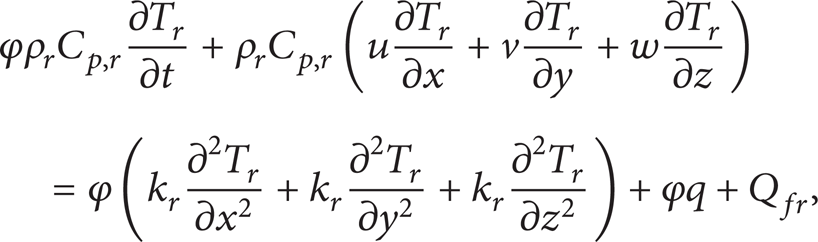
where the subscripts r and f refer to the resin and fiber, respectively. In the above equations, φ = 1 – φ f represents the volume porosity of the medium (ratio between the volume available for fluid flow and the total volume). Assuming the absence of voids, φ coincides with the resin volume fraction V r = 1 – V f · Q rf = – Q fr is the interfacial heat transfer between the fluid and the solid depending on the temperature difference, the interfacial area density, and the physical properties of the two phases. It should be borne in mind that in the porous model the DOC is treated as an additional scalar variable with transport properties existing only in the fluid phase and varying according to a source term generated by the reaction rate previously defined in (12). Similarly, the heat generation term q in (11) is restricted to the reactive resin and the exothermic reaction affects the fiber temperature by means of conductive heat transfer. As for the impregnation model, the software ANSYS-CFX [29] has been used to solve the porous thermal model employing a FV numerical scheme. The temperature and the DOC distributions are utilized to compute the resin viscosity and the viscous drag, according to (5) and (3), respectively.
2.4. Mechanical Analysis
As mentioned above, the process induced stress and distortions, including also the die-composite contact pressure, are predicted using the two different procedures. The former approach is based on the solution of a 2D quasi-static FE mechanical model, sequentially coupled with the 3D continuous thermochemical FE model. The latter is a semianalytical approach based on the applications of the well-established principles of the linear elasticity to the results provided by the above described porous model.
2.4.1. FE Model
In this model, the 2D cross section of the part is assumed to be moved along the pulling direction while tracking the corresponding temperature and DOC profiles provided by the FE model. A detailed description of this procedure, that is, the mapping of the predicted fields (T, α) to the 2D mechanical plain-strain model, is shown in Figure 6. The implemented mechanical FE model assumes that the longitudinal strains, that is, parallel to the pulling direction, are negligible with respect to the transverse components of the strain tensor. This approximation is well justified considering the remarkable difference, for pultruded products, between in plane (cross sectional) and out of plane (product length) dimensions, being the former of few square millimeters and the latter of several meters before the cutout. As a consequence, the problem can be reduced to a two dimensional plane strain analysis, as discussed in [25]. The corresponding transient distortions and the evolution of the process induced stresses and strains are calculated considering the temperature and the cure distributions, assuming the following contributions to the incremental total strain (Δ∊tot):

where Δ∊mech is the incremental mechanical strain, Δ∊th is the incremental thermal strain, and Δ∊ch is the incremental chemical strain due to the volumetric shrinkage of the resin. The details of the relations between the stress and strain tensors used in the present FE approach can be found in [25].

Representation of the coupling of the 3D Eulerian thermochemical model with the 2D Lagrangian plain-strain mechanical model including the rigid body surfaces and the mechanical BCs.
The CHILE approach [25, 27] has been implemented by means of user-routines in the commercial package ABAQUS to derive the instantaneous local resin elastic modulus (E r ), assuming a linear relation of the stress and strain tensors. The corresponding expression for the resin elastic modulus, assuming secondary effects of temperature as negligible, is given as follows:

The fictitious temperature T* is defined as the difference between the T g and the actual resin temperature T and expressed as follows:

where T g 0 represents the glass transition temperature of the uncured resin and a Tg describes the dependence of the glass transition temperature on the degree of cure. According to the CHILE approach, during the cure reaction, E r varies linearly with T* from the uncured (E r 0) to the fully cured (E r ∞) resin moduli. TC1 and TC2 are the critical temperatures, defining the beginning and the end of modulus development [27]. The effective mechanical properties of the composite are calculated using the self-consisting field micromechanics (SCFM) relationships, as reported in detail in [25]. For the proposed approach shown in Figure 6, the die is assumed to be rigid and therefore rigid body surfaces are added at the die-part interface instead of including the meshing for the whole die. Between the rigid surfaces and the composite part, a mechanical contact formulation is defined which restricts any expansion of the composite beyond the tool interface; however, any separation due to resin shrinkage is allowed. In this approach, the friction force at the contact condition is assumed to be zero (sliding condition). A generic view of the plane strain model including the rigid surfaces and the mechanical boundary conditions (BCs) is shown in Figure 6. It should be noted that, even if the constitutive behavior of the homogenized material is linear elastic, the solved boundary value problem is significantly nonlinear, due to the space and time variations of all physical and mechanical properties involved.
2.4.2. Semianalytical Analysis of Distortions and Pressure
The proposed semianalytical approach is based on the computation of a virtual unconstrained cross section of the processing material. It is assumed that during the process the position of the center of mass (barycenter) of the cross section is always preserved [11]. The composite distortions are related to the thermal expansion of each component and the chemical shrinkage of the reactive resin. As a consequence, each virtual dimension of the ith control volume can be computed multiplying its initial value by the correction factor as follows:

where δr, i and δf, i are the variations of a unit dimension of the ith volume entirely filled with resin and fiber, respectively. Defining the CTEs of the resin as α r and of the fibers in the transverse direction as αf, t, and the percentage volumetric shrinkage of the fully cured resin as γ r , it follows

where the subscripts r and f refers to resin and fiber, respectively. Here, the utilized temperature and the DOC values are the volume averaged values calculated by considering the results of the porous model described in Section 2.3.2. With reference to the circular cross section investigated, the dimensional variation Δr, i of the ith volume, along the radial direction, is given by
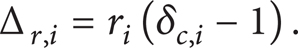
The total displacement Δ r = ΣΔr, i and the virtual radius r v can be evaluated by extending equation (21) to the whole radius. In particular, from the die inlet until the detachment point, due to the prevalence of the thermal expansion on the chemical shrinkage, the virtual section of the processing composite results reasonably greater than the die cavity. Consequently, the pultruded part is compressed by the die internal walls. In this case, the contact pressure is evaluated following the well-known principles of materials science for thick walled cylinders, schematizing the virtual section as a series of concentric and contiguous annulus (delamination phenomena are not included) and assuming plane strain hypothesis. As for the FE model described in Section 2.4.1, material elastic properties are evaluated according to local temperature and DOC, using the CHILE approach and the SCFM relationships. Taking into account this, the continuity of the material imposes the congruence of the circumferential strains ∊θ and the radial stress σ r at the boundaries between adjacent layers, using the subscript j to identify each annulus (increasing with the radial position) and the subscripts int and ext to localize the strain at the inner or outer radius of the annulus, respectively, which results in the following:

Furthermore, considering that the enlargement of the real cross section is prevented by the rigid die walls (the unconstrained section previously computed is a purely virtual one), the circumferential strain on the external radius results in the following:

providing the closure to the considered problem. A schematic representation of the calculation procedure is depicted in Figure 7. It is trivial to outline that, in correspondence with the external radius, the radial solicitation σ r equals to the opposite of the pressure σ acting on the die internal wall, allowing one to derive the frictional contribution using (6).
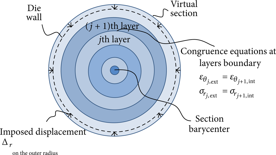
Pressure calculation scheme.
Frictional resistance vanishes when the shrinkage effect prevails, inducing the detachment of the material from the die. In this case, an additional TCR is induced between the die and the composite. TCR values are computed in the corresponding locations assuming that the empty space between the die surface and the processing composite is fulfilled by air. Since radial displacements and TCR values along the die length are not known as a priori, an iterative procedure, connecting the thermochemical model with the dimensional change model, has been implemented, until reaching the convergence of a temperature criterion.
3. Results and Discussion
3.1. Case Study
The pultrusion process of a UD graphite/epoxy composite rod with circular cross section is simulated to compare the numerical outcomes provided by the proposed models as well as with results discussed in the literature [6, 13]. The radius of the processing rod is 4.75 mm, while the length Ldie of heating die is 914 mm, which are adopted for the numerical and experimental analysis detailed in [6]. It should be noted that, in the performed simulations, the temperature distribution on the internal die surface is used to provide the required closure of the above described thermochemical problem; that is, the die is not included in the calculation domain, as also done in [6]. Despite the implemented thermochemical models that allow one to define more complex boundary conditions, this relatively simpler case has been reproduced in order to compare numerical results with data reported in [6]. The inlet temperature is assumed to be equal to the resin bath temperature (38°C), while the matrix material is assumed to be totally uncured (α = 0) at the same cross section. Only a quarter of the 3D model has been considered due to the symmetry and in order to reduce the computational effort. A schematic view of the simulation domain is depicted in Figure 8.

Schematic view of the pultrusion domain for the composite rod. All dimensions are in mm.
The variation of the internal section in the tapered inlet is not taken into account in the thermochemical model as well as for the stress and distortions calculations in the mechanical model. The reason is that the size of the tapered section is relatively small and there is almost no heat transfer, curing, and stress development observed in that region.
In addition, considering that the composite material in the die exit section is still at elevated temperature, it is reasonable to suppose that the cure reaction proceeds also in the postdie region, leading to a certain amount of DOC increase, as already discussed in [6, 25]. This aspect has been included in the model extending the length of the pultruded composite to the postdie region. The postdie is characterized by a total length Lpost-die equal to 1370 mm, ensuring that no further reaction will take place in the material. In the postdie region, convective cooling in the room temperature (27°C) is imposed as a boundary condition on the external surface of the pultruded product. The dependence of the convective cooling coefficient on the surface temperature is defined using the well-known principle of heat transfer for horizontal cylinder. The pull speed vpull has been defined as 5 mm/s [6].
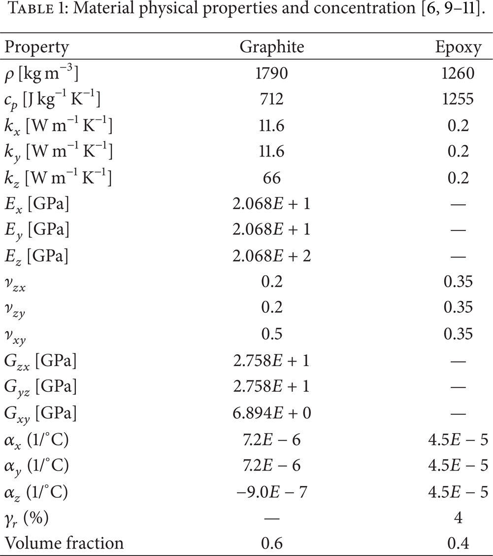
The pultruded composite rod consists of Shell Epon 9420/9470/537 resin and Graphite Hercules AS4-12K fibers (r f = 13 μm). The properties of components and the resin kinetic parameters are listed in Tables 1 and 2, respectively. The parameters used in the CHILE approach are given in Table 3.


3.2. Impregnation Analysis
The impregnation model is considered for the first 30 mm of the die, assuming that after this length flow perturbations induced by the convergent section of the inlet vanish. The tapered inlet has been modeled assuming a rounded shape with length L t and radius R t being equal to 6 and 6.35 mm, respectively [13]. The preform ratio, defined as the ratio between the cross sectional area of the impregnated material before and after the compaction due to the tapered inlet, is assumed to be 1.44, neglecting shape variations of the pulled material. As a consequence, the wetted fibers approaching to the inlet have been modeled as a cylindrical porous medium with radius being equal to 5.7 mm.
As aforementioned, a constant viscosity assumption is adopted, taking into account that generally in the very early part of the die no significant reaction is observed. The reference viscosity value has been obtained according to (5), considering the resin as fully uncured (α = 0) at a temperature equal to 38°C, as for the thermochemical models. It should be noted, however, that the catalyzed resin, before the impregnation and entering of the die, lays into the open bath for some time. During this period, a small amount of reaction cannot be excluded a priori. Even if the degree of crosslinking in the resin bath does not significantly affect the evolution of the solidification process, it can influence the viscosity for the impregnation and compaction analysis. This situation is investigated in the present work by simulating the compaction process using three different viscosity values: 1.05 Pa·s (α = 0), 1.5 Pa·s (α = 0.008) [13], and 2.60 Pa·s (α = 0.02). In the impregnation model, the die surfaces are modeled as rigid walls, defined with a no slip condition. An inlet condition is imposed to the inlet surface corresponding to the preform, while an opening condition allowing the creation of the resin backflow is applied on the surrounding surface. In both cases, a zero relative pressure is defined. The velocity of the processing material crossing the outlet section has been assumed to be equal to the pull speed.
In Figures 9–11 the results provided by the impregnation model are reported which show the pressure profiles at the centerline of the processing material (Figure 9), a streamline plot of the resin flow in the tapered region (Figure 10), and the calculated bulk compaction force (Figure 11). For all the simulated conditions, an increase in the pressure has been predicted before the intersection point, which is identified by the contact between the reinforced preform and the die internal surface and is depicted in Figure 9 by the vertical dashed line. This pressure variation is due to the effect of the resin backflow (well highlighted by the streamlines opposite to the pulling speed in Figure 10), which prevents the free flow of the resin inside the preform towards the nonreinforced zones. The same figure also highlights the excellent agreement between the obtained pressure profiles and the data reported in [13], confirming the validity of the implemented numerical model. Furthermore, as already indicated in [13], for the considered configuration more than half of the total pressure increase has already developed at the intersection point. It is also worth noting in Figure 10 that, at the very beginning of the straight portion of the die, the resin velocity converges on the pull speed imposed to the reinforcing fibers.

Centerline pressure rise in the tapered region of the die.

Streamline of the resin flow in the tapered region of the die.
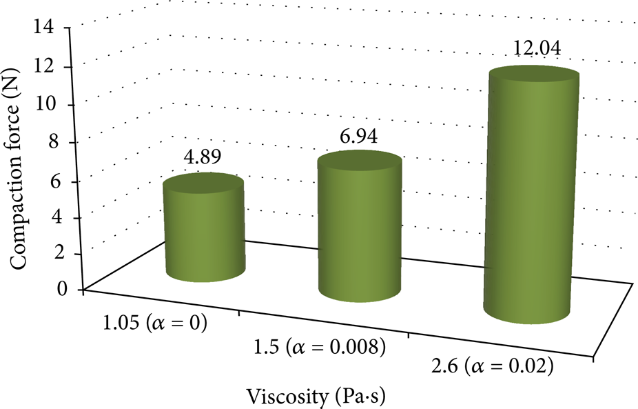
Influence of the resin viscosity (initial degree of cure) on the compaction term of the pulling force.
Obtained outcomes also show that the activation of the cure reaction inside the resin bath is quite undesirable, even if the degree of crosslinking achieved before entering the die is reduced. Indeed, the premature crosslinking of the catalyzed resin increases its viscosity and, as a consequence, higher pressures are needed to squeeze the excess resin out of the preform. This results also in a proportional increase of the pulling force contribution due to material compaction (Figure 11).
3.3. Thermochemical Analysis
The calculated centerline temperature and DOC profiles are shown in Figure 12 together with the temperature profile imposed on the die wall. It is seen that the predicted results match quite well with the available experimental data in [6]. This evidences that the numerical schemes adopted for the continuous homogeneous FE model (denoted as “CM” in Figure 12) and the porous nonhomogeneous FV model (denoted as “PM” in Figure 12) are stable and converged to a reliable solution. The temperature in the center of the composite rod becomes higher than the die wall temperature after approximately 390 mm from the die inlet due to the internal heat generation of the epoxy resin. At that point a peak of the reaction rate is obtained, inducing a sharp increase of the DOC. The maximum composite temperature is calculated approximately as 208°C. What is more, at the postdie region, the DOC is increased slightly which indicates that the curing still takes place after the die exit, as also observed in [6]. The centerline DOC is increased from 0.84 (at the die exit) to 0.87 (at the end of the process), while, at the surface, it varies from 0.80 to 0.83, indicating a global percentage increase of approximately 3.6%.
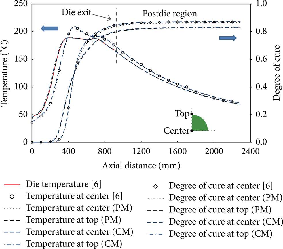
Temperature and DOC profiles: comparison of the present outcomes with the reference data [6].
The depicted DOC profiles in Figure 12 show an earlier activation of the cure reaction at the composite surface due to the rapid temperature increase related to conductive heat transfer from the die wall. As a consequence, the DOC at the external radius initially results higher than at the center. This trend varies after the activation of the reaction in the core of the material; indeed, the relatively low thermal conductivity of the resin prevents the heat generated at the center to flow towards the external zones, inducing a significant and localized temperature increase at the center, which strongly promotes monomers crosslinking. It is worth noting that the cure crossover (intersection between the DOC profiles at the center and at the top) is reached approximately at α = 0.5, that is, well above the gel point (α = 0.265) of the considered resin system, indicating a delay in the establishment of the desired in-out solidification direction. Indeed, as evidenced by the viscosity profiles depicted in Figure 13, the activation of the cure reaction implies a sharp viscosity increase at gelation, occurring earlier at the top surface, at a distance approximately equal to 360 mm from die entrance and separating the liquid zone (where viscous drag acts) from the gel zone (dominated by frictional resistance). The same viscosity trend is observed at the center of the composite rod after approximately 405 mm from the die entrance. It should be also noted that, in the first 200 mm from the inlet, the temperature increase leads to a slight viscosity reduction before the beginning of crosslinking phenomena, as also highlighted in Figure 13.

Extension of the liquid, gel, and solid zone, as evidenced by viscosity profiles at top and work piece radius.
In the same figure (Figure 13) the work piece radius, as a function of the axial distance, is reported. As highlighted by numerical outcomes, in the liquid zone the materials thermal expansion prevails on chemical shrinkage, leading to a virtual radius of the work piece greater than the die internal radius. As a consequence a further pressure increase (shown in what follows) is to be expected. Even if this pressure increase does not theoretically implies further contributions to the total pulling force (being the wall surface parallel to Fpull), from a practical point of view it is very interesting since, in conjunction with the aforementioned viscosity reduction, it promotes the reduction of voids in the final product. As can be seen, both models fairly agree with the individuation of the detachment point, which is the intersection point between the virtual radius and the die internal radius during shrinkage. Please note that the zero radial displacement provided by the FE model (CM) is due, in agreement with reality, to the nonpenetrating condition applied at the mechanical contact between the composite and the rigid die surface [25]. The detachment point for the outer surface of the composite rod is found to be approximately at 540 mm from the inlet (more precisely 535 mm and 545 mm for the FEM and SAM); as a consequence the die length interested by the frictional effect (gel zone) is estimated to be approximately 180 mm. The delayed position of the detachment point predicted by the SAM with respect to the FEM suggests also that a relatively major computation of the virtual radius (or radial displacement of the cross section). This aspect can be related to the assumption of the lumped CTE employed in the FE model in contrast with the usage of a different CTE for each constituent (when the resin is in liquid phase) adopted by the SAM. After the detachment point, TCRs are induced between the work piece and the die. Nevertheless, very negligible differences (less than 0.5°C) in the temperature distributions have been found with and without the TCR inclusion in the calculations. The work piece radius in the exit section as provided by the analytical calculation coupled to the finite volume model, results 4.742 mm, in good agreement with the value (4.739 mm) reported in [11]. A slight difference (∼0.003 mm = 3 μm) regarding the work piece radius at the exit calculated using the FE model and the semianalytical procedure has been found. As can be seen in Figure 13, after the detachment point, the evolution of the radial distortion differs between the aforementioned approaches. The reason for this deviation could be found in the oversimplification of the semianalytical model (SAM), in which the displacements are calculated only in the radial direction without taking the effect of the mechanical behaviors in the longitudinal direction into account.
3.4. Mechanical Analysis
The evolution of the process induced transverse normal stresses in the x-direction (S11) is shown in Figure 14(a). It is seen that at the end of the process, tensile stresses prevail at the inner region (center) and compression stresses occur at the outer region (top) while upholding the self-static equilibrium in which there is no applied external load. This observation resembles with the one presented in [25]. The stress levels are found to be relatively small (<1 MPa). The main reason is that there are an almost uniform temperature and DOC developments over the cross section of the composite rod which provides relatively lower through-thickness gradients promoting almost no residual stresses at the end of the process. The variation in S11 is due to the internal competition between expansion and contraction of the part. The effective longitudinal and the transverse moduli (calculated by the SCFM) of the composite rod at the end of the process are found to be 130.2 GPa and 9.7 GPa, respectively, which agrees well with typical values given in [30] for T300 carbon/epoxy with a fiber volume fraction of 60%. In Figure 14(b) the resin modulus development due to monomers crosslinking is depicted. It is seen that almost same evolution pattern is obtained using the CHILE model in FEM model and SAM model.

In-plane stresses (S11) evolution at the center and at the top of the composite rod (a) and resin modulus development at the same locations as a function of the axial distance (b).
Undeformed contour plots of the stresses S11 (in x-direction) and S22 (in the y-direction) are shown in Figure 15. As expected, the S11 distribution is almost symmetric with the S22 distribution with respect to the diagonal of the composite rod, since all the mechanical boundary conditions are the same. The maximum normal tensile and compression stresses are found to be approximately 0.26 MPa and −0.82 MPa, respectively, for S11 and S22.

The undeformed contour plots of the inplane stresses: S11 (a) and S22 (b).
In Figure 16, the contact pressure profiles (between internal die surface and the outer surface of the part, that is, top point indicated in figure) provided by the implemented models (FEM, SAM) are shown. Both models highlighted a progressive pressure increase (up to approximately 0.2 MPa for the FEM and 0.27 for the SAM) from the die inlet to the strong activation of the resin reaction since the composite part tries to expand because of the temperature increase; however the internal die surface restricts this expansion. The difference between these two predictions is due to the aforementioned considerations in virtual section calculations, which relies on the specific assumptions in the FEM and in the SAM. Afterwards, due to resin chemical shrinkage, a continuous pressure reduction is observed until the detachment occurs.
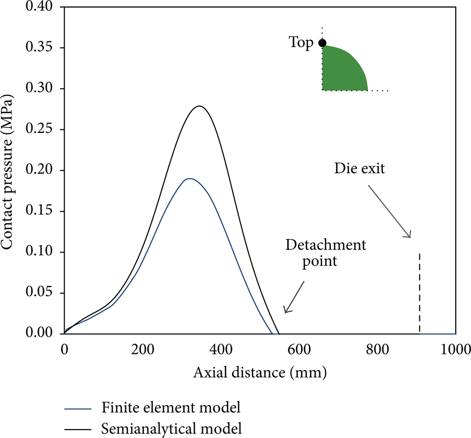
Contact pressure profiles.
According to the calculated viscosity and pressure profiles, in the thermochemical analysis the total pulling force together with its components is predicted (Figure 17). For the calculation of the frictional resistance, the friction coefficient μ has been assumed to be 0.25, as also used in [19]. Numerical outcomes show that, for the simulated process, the viscous force represents the principal amount of the total resistance, being Fbulk = 4.9 N, Fvis = 313.7 N, and Ffric = 184.1 N, as predicted by the semianalytical procedure. A relatively smaller frictional resistance (112.9 N) is predicted by the FE mechanical model, due to the lower contact pressure profile in Figure 16. The key role played by the viscous drag with respect to the frictional force can be related to the reduced die length affected by the frictional phenomena and to the delayed development of the resin (and the composite) modulus. The contribution due to the material compaction is found to be not significant as compared to other amounts, being less than 1% of the total load.
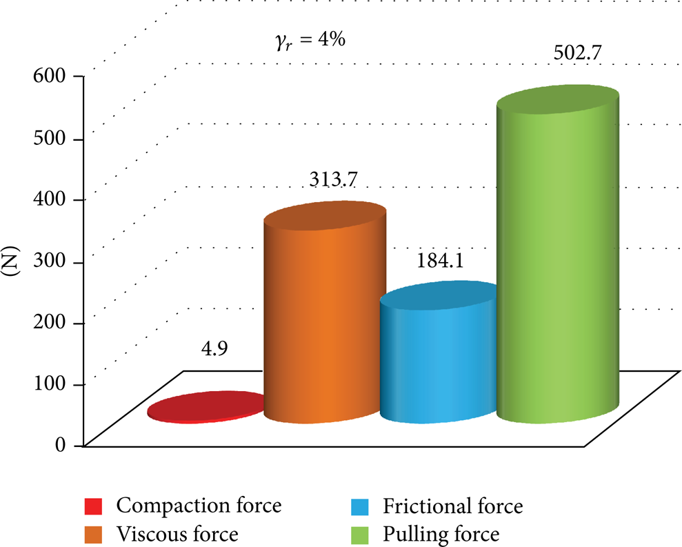
Contribution to the pulling force as provided by the impregnation, viscous, and frictional models (SAM), assuming chemical shrinkage and initial viscosity to be 4%—1.05 Pa·s.
4. Conclusions
In the present work, different approaches for modeling and simulations of several physical aspects, such as fluid flow, heat transfer, chemical reaction, and solid mechanics, involved in a conventional pultrusion process are proposed and compared. The proposed models are based on different numerical techniques (FEM, FVM) as well as the analytical calculation. Taking into account the discussed outcomes, it can be concluded that
the resin pressure increases at the tapered die inlet, promoting the backflow of the excess resin; however, as soon as the straight portion of the die begins, a flat velocity profile is enforced. It is found that the compaction force increases with the viscosity (or degree of cure) of the resin in the impregnation bath;
adopted numerical schemes (FEM, FVM) are found to be accurate and converged to a reliable solution, since the predicted values match well with the reference data [6]. Moreover, both models fairly agree in the evaluation of viscosity profiles, dimensional variations and extension of the three zones (i.e., liquid, gel, and solid). The inclusion of the thermal contact resistance due to material contraction inside the die in pultrusion modeling does not affect the simulation results significantly;
in the initial portion of the curing die, the thermal expansion of the processing materials dominates the resin shrinkage, which induces a progressive contact pressure increase and, consequently, frictional resistance after gelation. However, as the cure reaction proceeds, the chemical contraction of the reactive resin prevails causing the detachment of the work piece from the die internal surface and the vanishing of the contact pressure as well as the frictional force;
in the residual stress model, relatively small residual stress values were predicted at the end of the process due to the uniform distribution of the temperature and degree of cure over the cross section of the composite part having a relatively small diameter (9.5 mm). The thickness of the composite part together with the total volumetric shrinkage of the resin has an important effect on the residual stress evolution [25]. At the end of the process, it is found that tension stresses prevail for the center of the part since it cured later and faster as compared to the outer regions where compression stresses were obtained while upholding the self-static equilibrium;
the viscous drag is found to be the main contribution as the frictional force to the overall pulling force, while the contribution due to material compaction at the inlet is found to be negligible.
Investigating the several aforementioned processing physics simultaneously provides a better understanding of the entire pultrusion dynamics at a glance and therefore this study would be very much of interest to the composite manufacturing processing community and especially to scientists and engineers in the field of manufacturing process modeling.
Footnotes
Acknowledgment
This work is a part of DeepWind project which has been granted by the European Commission (EC) under FP7 Program Platform Future Emerging Technology.