
Abstract
A motion tracking system for objects can track and display the movement of objects, including sporting equipment. Recently, it has become evident that individuals who actively participate in sport or fitness activities can benefit from the feedback provided by such a system. A motion tracking system for sporting equipment can improve the sporting skills of users and help prevent injury. In this study, a ubiquitous motion tracking system that tracks sporting equipment using the sensors installed in an activity monitor is proposed and constructed. The activity monitor with the tracking sensors can be attached to places on the body or on sports equipment to calculate the speed and acceleration of these objects. The ubiquitous motion tracking system consists of four modules: a tracking sensor module and a communication module in an activity monitor, a communication module in a USB dongle, and a motion analyzer module in a laptop PC. For experiments, an activity monitor with the tracking sensor module and the communication module is attached to a golf club, and a golf swing is taken. The results of the experiments show that the motion data of sporting equipment can be captured and analyzed easily, in both an indoor environment and an outdoor environment.
1. Introduction
A tracking system for moving objects can track and display the movement of objects, including sporting equipment. Such a system is capable of capturing every movement of the objects that it tracks and can thus provide important data, such as the speed and acceleration of an object, which users can make use of to improve their sporting skills or prevent injury. Examples of moving objects include sporting equipment (golf clubs, bats, etc.) and human body parts (wrists, ankles, etc.). Recently, in addition to professional athletes, this technology has enabled people who cannot afford to hire professional coaches to obtain movement analysis of their body or their sporting equipment by themselves.
In this study, a ubiquitous motion tracking system that tracks sporting equipment using the sensors installed in an activity monitor is proposed and constructed. The activity monitor with the tracking sensors can be attached to human body parts or sports equipment to calculate the speed and acceleration of these objects. The ubiquitous motion tracking system consists of four modules. A tracking sensor module consisting of a gyro sensor and an acceleration sensor captures the motion data of the sporting equipment and calculates its movement information, such as the speed or acceleration of the equipment. A communication module transmits this information to a USB dongle module through RF wireless communication. The tracking sensor module and the communication module are installed in an activity monitor, one of the personal healthcare devices (PHDs). A USB dongle module attached to a laptop PC receives the information from the activity monitor for the laptop PC. Finally, a motion analyzer module in the laptop PC analyzes the movement information to display the motion of the equipment. For experiments, an activity monitor with the tracking sensor module and the communication module is attached to a golf club, and a golf swing is taken. The results of the experiments show that motion data of sporting equipment can be captured and analyzed easily, both in an indoor environment and an outdoor environment.
The remainder of this paper is organized as follows. Section 2 describes the related studies, Section 3 explains the ubiquitous motion tracking system for sporting equipment proposed in this paper, and it also shows the results of an experiment using the motion tracking system constructed in this study. Finally, Section 4 draws some conclusions and discusses the direction for future research.
2. Related Studies
Most studies on movement tracking systems have dealt with the fields of gaming, animation, virtual reality, sports, entertainment, medical training, and so forth [1–7]. A typical approach is to use motion capture techniques. Motion capture (or motion tracking) is the process of recording the movement of objects [8].
There are several possible approaches to motion capture technologies: optical, mechanic, magnetic, and inertial. The most frequently used approach is to use optical motion capture technologies, as shown in Figure 1.

Optical motion capture.
Specially designed markers are placed at specific points of objects, and video cameras in fixed positions track the motion of the markers. Motion data captured by the cameras is analyzed by image processing software. Passive markers reflect light, so that the cameras can track only the bright reflective markers [9]. Active markers use LEDs which emit infrared light by themselves [10]. The optical approach, when a large number of cameras are used, can capture very accurate motion data inside a specially designed room. However, an expensive environment is required for this approach. Recently, inexpensive markerless optical motion tracking technologies have been studied, which are attractive because they require neither markers nor a special setup [11]. However, this approach requires the development of very accurate and stable motion tracking algorithms. Generally speaking, the optical approach can capture accurate motion data indoors but has difficulty tracking objects outdoors.
In the inertial approach, inertial sensors are used to measure rotation and acceleration data of objects [12]. This approach does not require markers, special equipment, or complex image processing algorithms. The measured data is transmitted wirelessly to a computer, which analyzes the data. Therefore, the approach can be used inexpensively, both outdoors and indoors. However, the approach may produce inaccurate results when no initial absolute position is provided, since the sensors only provide motion data relative to the previous position of the object.
In the mechanical approach, a skeletal-like mechanical structure is attached to an object to track joint angles of the object [13]. Like the inertial approach, the motion data captured can be transmitted wirelessly to a computer, which analyzes the data. The approach can be used outdoors as well as indoors inexpensively. However, the approach also may produce inaccurate results when there is no initial absolute position provided, since the sensors only provide motion data relative to the previous position of the object. The magnetic approach calculates the motion data of an object based on the relative magnetic flux of three orthogonal coils [14]. This approach is less expensive than the optical approach, since the number of sensors (or markers) is smaller and the volume of captured data is much smaller. However, the accuracy of the motion data can be compromised by magnetic and electronic interference from wiring, computers, lights, and so forth.
Tracking techniques focusing on the motion of sporting equipment have also been developed. One of the most common objects to which tracking techniques are applied is a golf club [15–19]. For the purpose of golf swing correction, a series of photographs is taken of golf club motion using a camera with a high shutter speed, and the resulting photographs are then displayed in succession, as shown in Figure 2. A video is sometimes also provided for the same purpose. The movement data obtained from these techniques provides good views of the swing paths of golf clubs and body parts. However, other than that, the movement data obtained from the techniques is limited.

A series of photographs of a golf club motion.
Techniques in which sensors are attached to wrists or golf clubs have been developed to display the movements of the wrists or golf club. Various movement data can be obtained, including the speed of the object, as shown in Figure 3.

Various motion data obtained from sensors attached to a golfer's wrists.
3. Motion Tracking System for Sporting Equipment
3.1. System Structure
Figure 4 shows the structure of the ubiquitous motion tracking system proposed in this paper. It consists of four modules. The tracking sensor module measures the movement data of an object, given by variables such as acceleration, direction, and angle of swing by using a 3-axis acceleration sensor and a gyro sensor, which are installed in an activity monitor. Based on the movement data, it also calculates movement information, such as the speed and acceleration of the object. The communication module transmits this information to a USB dongle module by RF wireless communication. The tracking sensor module and the communication module are installed in an activity monitor, one of the Personal Healthcare Devices (PHDs) [20–23]. A USB dongle module attached to a laptop PC receives the information from the activity monitor for the laptop PC. Finally, a motion analyzer module in the laptop PC analyzes the movement information to display the motion of the equipment.

Structure of the ubiquitous motion tracking system.
Figures 5 and 6 show the block diagram and the PCB (printed circuit board) of the activity monitor, respectively. The tracking sensor module in the activity monitor measures the movement data of the object where the activity monitor is attached.
Gyro sensor: this has a 16-bit resolution, enabling the 3-axis measurement of a swing angle up to 1,000 dps (degree per second). Acceleration sensor: this has a 16-bit resolution, enabling the 3-axis measurement of acceleration up to 24 G. MCU: this calculates movement information based on movement data from the sensors mentioned above. This also performs RF wireless communication with the USB dongle.

Block diagram of the activity monitor.

PCB of the activity monitor.
Figures 7 and 8 show the block diagram and the PCB of the USB RF dongle, respectively. Attached to a laptop PC, the USB RF dongle enables RF wireless communication between the activity monitor and the laptop PC.

Block diagram of the USB RF dongle.
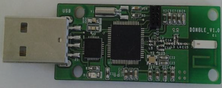
PCB of the USB RF dongle.
Figure 9 shows the communication message format used for communication between the motion tracking system and a laptop PC. The two leftmost bytes (0X07, 0XFF) represent the header of the message, and the rightmost byte represents the trailer of the message. The message sequence number is stored in the third byte. The acceleration and the swing angle at the moment of measurement are stored in bytes 3–8 and 9–14, respectively.

Communication message format.
The measurement data is represented in 32768-biased format in such a way that the data varies from −32767 up to +32767. The number 32768 represents zero acceleration. An increase by 1365 in bytes 3–8 represents an increase of 1 G in acceleration. For example, when the number 34133 (31403) is transmitted, it means that 1 G (−1 G) of acceleration is observed at the moment of the measurement. An increase by 32.7 in bytes 9–14 represents an increase of one degree in the swing angle. The completion of a swing triggers the transmission of the measurement data from the sensor module to a laptop PC. For one swing, 300 messages containing the measurement data are sent in the stream mode.
3.2. Experiment Results
For the experiments, an activity monitor installed with the tracking sensor module and the communication module is attached to a golf club as shown in Figure 10, and a golf swing is taken. The USB RF dongle module is attached to a laptop PC to receive the movement information for the laptop PC, as shown in Figure 11.

An activity monitor with the tracking sensor module attached to a golf club.

A USB dongle attached to a laptop PC.
The tracking sensor module measures 300 instances of motion data for three seconds, which includes a two-second period prior to the specific movement being taken. Figure 12 shows a sample of motion data (acceleration and angular speed) obtained from the sensors mentioned previously. Every measurement data is 16 bytes long.

Sample of the motion data.
From the motion data in Figure 12, graphs of the swing angle and the acceleration of the swing can be obtained by the motion analyzer module, as shown in Figures 13 and 14, respectively. For an example, let us look at the first row of the table shown in Figure 12. It represents a communication packet of sequence number 0 received from the activity monitor. Since the two bytes following the sequence number represent an acceleration value on the x-axis (Acc_x), Acc_x = 131(0x83) * 256 + 64(0x40) = 33600, which is the first Acc_x value in Figure 14. The first values of Acc_y and Acc_z can be similarly obtained.

Graph of the swing angle.
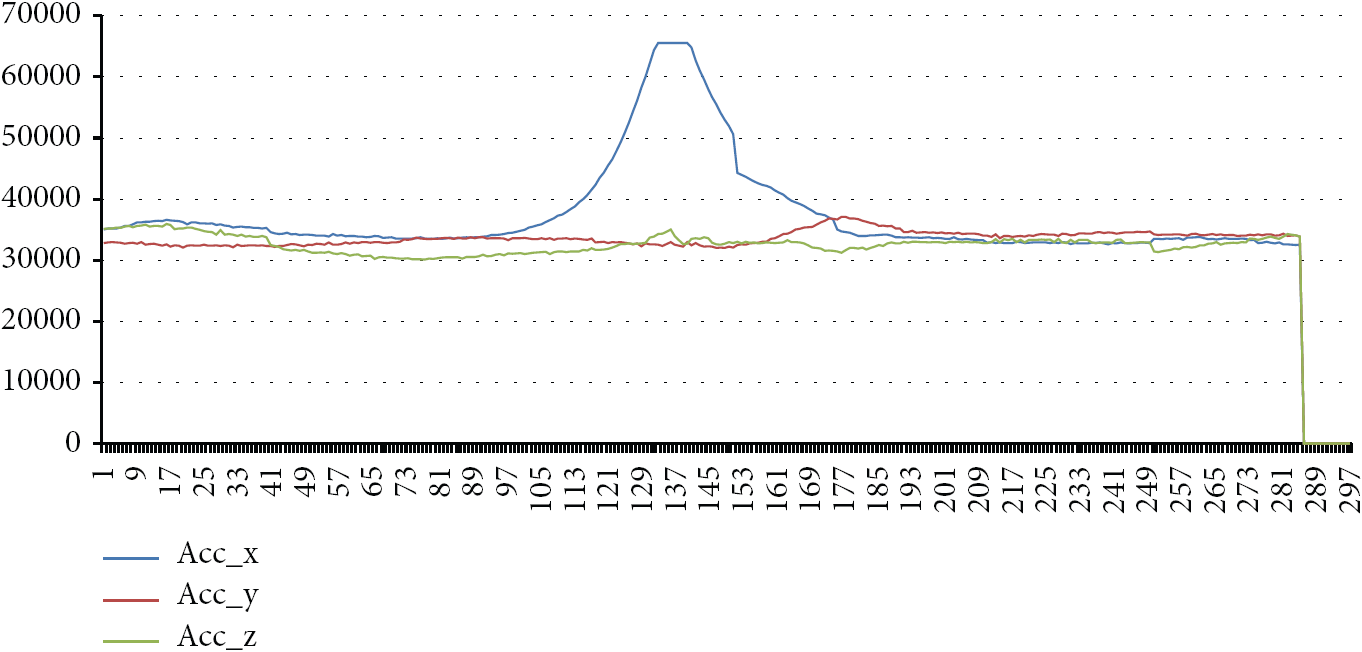
Graph of the swing acceleration.
Of the three acceleration axes, the y-axis represents the vertical movement of the golf club. As shown in Figure 14, the curve of the y-axis moves sharply, which means that the swing is made and the golf club is moved up and down at an extreme rate. At the same time, as noticed in Figure 13, the golf club changes its course sharply in every direction.
4. Conclusions
In this study, a ubiquitous motion tracking system that tracks sporting equipment using the sensors installed in an activity monitor is proposed and constructed. The ubiquitous motion tracking system consists of four modules. A tracking sensor module consisting of a gyro sensor and an acceleration sensor captures the motion data of sporting equipment and calculates its movement information, such as the speed or acceleration of the equipment. A communication module transmits this information to a USB dongle module via RF wireless communication. The tracking sensor module and the communication module are installed in an activity monitor, one of the PHDs. A USB dongle module attached to a laptop PC receives the information from the activity monitor for the laptop PC. Finally, a motion analyzer module in the laptop PC analyzes the movement information to display the motion of the equipment in order to present the graphs of the swing angle and the acceleration of the swing of the equipment. For experiments, an activity monitor with the tracking sensor module and the communication module is attached to a golf club, and a golf swing is taken. The results of the experiments show that the motion data of sporting equipment can be captured and analyzed easily, in both an indoor environment and an outdoor environment.
The system proposed in this paper can be used in several areas. The activity monitor could be attached to sporting equipment, such as a golf club or a bat. And the motion analyzer module can analyze the swing patterns of a user to improve his/her skills, or to prevent injuries. The activity monitor can be attached to places on the bodies of senior citizens who have no caregivers nearby, enabling medical staff to remotely monitor a patient's activity using the motion analyzer module.
Currently, based on the motion information from the activity monitor, a more powerful analyzer module that shows the movement of the equipment in various directions is being developed in such a way that will enable users to check the swing path as well as the speed or acceleration of the golf club. A motion analysis algorithm based on the motion data will be studied afterwards also.
Footnotes
Acknowledgment
This research was supported by the Basic Science Research Program through the National Research Foundation of Korea (NRF), funded by the Ministry of Education, Science and Technology (no. 2012-013549).