
Abstract
We propose a linearization method for reducing the effect of nonlinear frequency sweep in a frequency-modulated continuous-wave (FMCW) based laser range sensor. In FMCW laser range sensors, nonlinear frequency sweep can severely degrade the measurement accuracy because it gives the system ambiguity when determining the target range. In general, voltage controlled oscillators (VCO) which are used for frequency modulation show nonlinear frequency sweep property even though the input voltage signal is a linear ramp signal. To solve this problem, we adopt an additional fixed delay structure to extract the nonlinearity and compensate it. The proposed linearization method has been worked out through the numerical process and the simulation, and this method effectively eliminates the nonlinear frequency sweep problem.
1. Introduction
Laser range sensors are remote distance sensing devices with typical applications, such as solid-target detections, 3D vision, localization, and robotics [1–3]. To determine the distance, projecting an optical signal onto an object and processing the reflected or scattered signal are performed in laser range sensors. Conventionally, pulsed time-of-flight (TOF), phase-shift measurement, and frequency-modulated continuouswave (FMCW) are considered as major techniques for laser range sensors [4]. Pulsed TOF range sensor determines the distance by measuring the round trip time of the optical pulse signal. This method provides high signal-to-noise ratio (SNR) and shows good performance; however high cost and large size are the drawbacks [5, 6]. Phase-shift range sensor determines the distance using phase difference between reference and reflected signals. Using this method, simple and low cost laser range sensor can be realized. However, intermediate frequency drift and influence of the crosstalk degrade the performance of the phase-shift technique [7, 8].
To avoid these problems, we focused on the FMCW laser range sensor. In an FMCW laser range sensor, a sinusoidal signal with a constant rate of frequency change is transmitted, and this signal is reflected by a target. The frequency difference between the transmitted and the reflected signals, called the beat frequency, contains the distance information. As long as the frequency sweep is linear, the beat frequency is focused at a single frequency, and the target distance can be easily extracted. However, in practice, the linear frequency sweep profile is not easy to obtain. If there is nonlinearity in the frequency sweep, the beat frequency is not focused at a single frequency, and it is difficult to determine the exact range [9–11]. There are several techniques for linearization of the frequency sweep, and most of them focused on the linearization of the voltage controlled oscillator (VCO) frequency sweep because it is the crucial nonlinearity source of the system. The techniques are mainly of two types: one is open-loop correction [12, 13] and the other one is closed-loop correction [14–16]. The open-loop correction method modifies the VCO tuning voltage properly to get a linear frequency sweep using a look-up table. However, since the frequency is controlled only by an open-loop system, inevitable frequency drifts, due to temperature, environmental conditions, aging, and so forth, cannot be compensated for. The closed-loop correction method adopts a phase locked loop (PLL) circuitry to linearize the frequency sweep. However, because PLLs are dynamic systems, any changes in the system input will cause the output not to follow immediately but to exhibit some transient behavior. Such errors in the output frequency will have a negative influence on the FMCW measurement result.
To solve these problems, we propose a method for correction of frequency-sweep nonlinearity in a signal processor instead of linearization of the VCO frequency sweep. For linearization, an additional fixed delay structure is adopted, and the frequency-sweep nonlinearity is extracted and used for compensation. We validate our linearization method with numerical analysis and computer simulation.
2. Nonlinearity Correction Method
In FMCW technique, a transmitter produces an FMCW signal, that is, a sinusoidal signal with a constant rate of frequency change. This signal is backscattered by a target and goes back to the emitter. Beat frequency which is frequency difference between transmitted signal and backscattered signal contains the distance information.
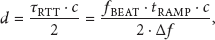
In intensity-modulated FMCW laser range sensor, a laser diode (LD) transmits an optical signal with direct modulation, and a VCO is adopted for frequency modulation. The output signal frequency of the VCO is controlled by input voltage. If the input voltage of VCO is a ramp signal, an optical signal with a constant rate of frequency increase is generated. This optical signal is backscattered by a target and goes back to a photo detector (PD) which can transfer optical signal to electrical signal. Using a mixer and a low pass filter (LPF), a signal with beat frequency is extracted. Then the distance of the target can be expressed as
To solve the nonlinear sweep problem, we propose equipping the FMCW laser range sensor with an additional fixed delay structure, as depicted in Figure 1.
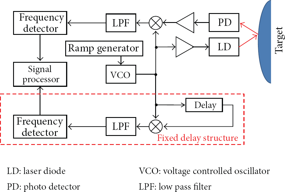
Block diagram of the proposed FMCW laser range sensor.
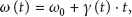
As shown in Figure 1, a fixed delay structure is added for linearization. When a voltage ramp signal is given to the VCO, the angular frequency of the VCO output signal can be expressed as


A frequency detector is used for detecting the frequency of the signal after LPF. A reciprocal frequency counter can be used as the frequency detector. Because the reciprocal frequency counter measures the period for one cycle of the waveform, it can support high resolution and very fast readings. Also, a Schmitt trigger circuit can be used at input stage of the frequency detector so that noise does not cause spurious edges. Because frequency is derivative of phase, the angular frequency to be detected is expressed as

As we can see in (8), if the tuning rate
To solve this problem, we added a fixed delay structure for obtaining the tuning rate. The frequency detector can detect the frequency difference between the VCO output and delayed output signal, expressed as


Because the time delay is much smaller than frequency sweep time of the ramp signal as mentioned above, t is larger than

The derivative of the tuning rate can be obtained from (9) and expressed as

Using (8) and (12), we can obtain a quadratic equation for

The solutions of (13) are expressed as

There are two solutions, and the solution in the detectable range is selected. The obtained round trip time is constant over the measurement time, lying between the maximum round trip time and the frequency sweep time. In (14), t can be any value of the measurement time. The target range can be obtained using a simple relation between distance and time expressed as

3. Results and Discussion
We evaluate the proposed method using a computer simulation. The frequency sweep range and sweep time of a ramp signal are 500 MHz and 1 ms, respectively, and the measurement time slot is 0.2 to 1 ms. Figure 2 shows the simulation condition.

Simulation condition.
To evaluate the proposed method, we modeled a nonlinear frequency sweep and applied it to the FMCW laser range sensor. Figure 3 shows three kinds of frequency sweep patterns for each tuning rate.

Three kinds of frequency sweep patterns for each tuning rate.
We modeled one ideal linear and two kinds of nonlinear sweep patterns. Table 1 lists the tuning models.
Tuning models.

When the target range is 30 m, the beat frequencies and obtained target range for each case are shown in Figures 4(a) and 4(b), respectively. As shown in Figure 4(a), when the frequency sweep is linear, the beat frequency is focused at a single frequency, 100 kHz, and the target range, 30 m, can be easily obtained. However, when the frequency sweep is nonlinear, it is difficult to extract the exact beat frequency, and the measurement accuracy is degraded. For case II, the obtained target range in the measurement time can vary between 15 and 34 m, and, for case III, the obtained target range can vary between 12 and 58 m, as depicted in Figure 4(b).

(a) Beat frequencies and (b) obtained target range for the tuning rate models.
Two kinds of nonlinear frequency sweep patterns are applied in the proposed method. Figures 5(a) and 5(b) show the simulation results of the obtained target range plotted against the measurement time after linearization for case II and case III, respectively. As we can see that, in both results, the target range is almost constant over the measurement time and can be obtained successfully.
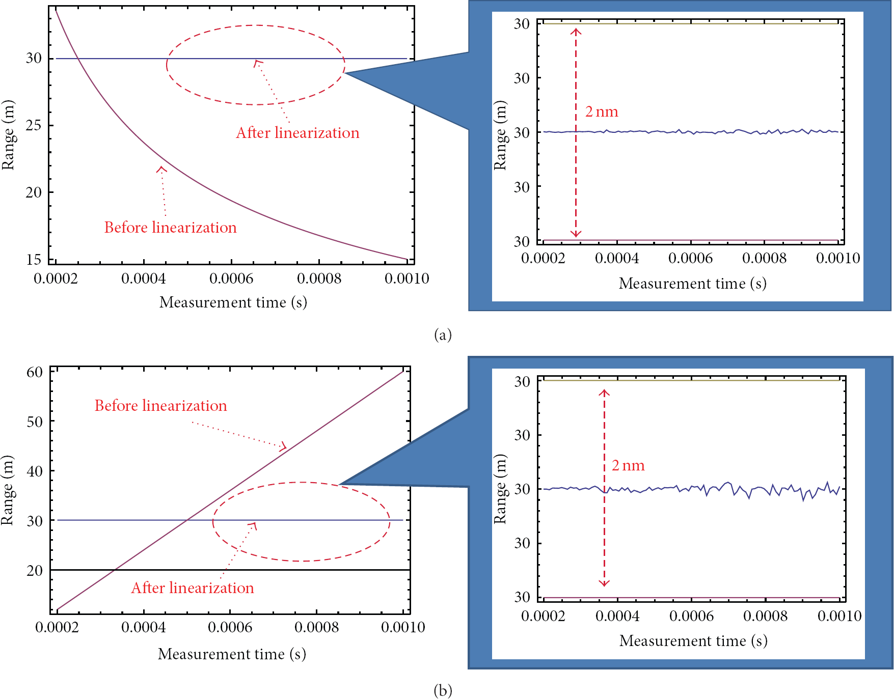
Simulation results after application of the proposed linearization method for the nonlinear frequency sweep of (a)
4. Conclusions
We have proposed a linearization method using an additional fixed delay structure in intensity-modulated FMCW laser range sensor. For correction of the nonlinear frequency sweep problem, a fixed structure was adopted to extract the tuning rate, and the target range was calculated using the obtained tuning rate. We modeled three kinds of frequency sweep patterns and applied them to the FMCW laser range sensor. When the frequency sweep was linear, the beat frequency was focused at a single frequency, and the target range was easily extracted. On the other hand, when the frequency sweep was nonlinear, there were multiple frequency components that could not extract the exact target range. From the proposed linearization method, the simulation results clearly showed that the proposed method effectively eliminates the nonlinear frequency sweep problem and improves the measurement accuracy.
Footnotes
Acknowledgments
This work was supported by Priority Research Centers Program through the National Research Foundation of Korea (NRF), funded by the Ministry of Education, Science and Technology (2009-0093828), and by the National Research Foundation of Korea (NRF) Grant funded by the Korean government (MEST) (no. 2011-0017081).