
Abstract
Vortex-induced vibrations (VIV) of three circular cylinders in equilateral-triangle arrangement are numerically investigated. The Reynolds number based on the free stream velocity D is 150. The gap spacing between the cylinders is set as 4D and all cylinders are free to vibrate in both transverse and in-line directions. The incompressible Navier-Stokes equations in two dimensions are solved by a four-step fractional finite element method. Simulations are carried out for three typical flow incidence angles (i.e., α = 0°, 30°, and 60°) and a wide range of reduced velocities (3 ≤ Ur r ≤ 12). Numerical results show that the responses of these cylinders, including the vortex shedding frequencies, the vibration amplitudes, and the motion trajectories, are significantly affected by the flow incidence angle and the reduced velocity. Some typical vorticity fields are also shown to investigate the flow interference between the cylinders.
1. Introduction
Vortex-induced vibrations (VIV) of cylindrical structures are a subject that has attracted lots of attention due to its importance in engineering applications, such as offshore platforms, marine risers, heat exchangers, and transmission cables. The VIV of a single cylinder has been already studied extensively in the recent decades. It is well known that an important phenomenon associated with free vibration of a cylinder is the synchronization or lock-in. For a certain reduced velocity range, the vortex shedding frequency approaches the structural natural frequency, and the cylinder experiences severe resonant vibration. More Details about the VIV of a single cylinder can be found in the review papers by Williamson and Govardhan [1], Sarpkaya [2], Gabbai and Benaroya [3], and recently by Bearman [4].
The complexity of the VIV dynamics is considerably increased when the cylinders are grouped in proximity and allowed to vibrate freely as a coupled system [5]. The flow field and the responses of the cylinders can be quite different from those observed when the cylinders are isolated in the fluid. At present, many experimental and numerical investigations have focused on the VIV of two cylinders. For example, Zdravkovich [6] carried out experiments on the behavior of two flexible cylinders placed in various arrangements and observed that the vibration amplitude strongly depended on the relative locations of the two cylinders. The numerical study of Mittal and Kumar [7] about the VIV of two cylinders in tandem with a separation distance of 5.5D (D is the cylinder diameter) showed that the response of the upstream cylinder was similar to that of a single cylinder while the downstream one experienced disorganized vibrations. Papaioannou et al. [8] numerically studied the effect of spacing on the vibration responses of two cylinders in tandem and found that the onset and the range of lock-in changed with cylinder spacing along with the maximum vibration amplitude of the downstream cylinder. Prasanth and Mittal [9, 10] numerically investigated the VIV of two cylinders in tandem and staggered arrangements. It was observed that the downstream cylinder exhibited very large amplitude transverse vibrations in both arrangements. Huera-Huarte and Gharib [11, 12] experimentally studied the VIV of two cylinders in tandem and side-by-side configurations. Their experiments showed that the flow interference between the side-by-side cylinders became very weak when the centre-to-centre spacing exceeded 3.5D. Bao et al. [13] conducted a numerical investigation on the VIV of two tandem cylinders with varying natural frequency ratios. The authors found that the condition of the occurrence of a dual-resonance existed over a broad range of tested natural frequency ratios.
The VIV of cylinder group is more often encountered in engineering field, but this issue has not been investigated as extensively as the single and two cylinders. Kubo et al. [14] experimentally studied the aerodynamic responses of two, three, and four elastic cables with various arrangements and centre-to-centre spaces. The results showed that the optimum configuration of multiple cable systems was the turning regular triangle arrangement with space of 4D. Lin and Yu [15] carried out an experimental study on the free vibration of a monitored flexible cylinder surrounded by one to six flexible cylinders. The effects of the incoming velocity boundary, the number of the surrounding cylinders, and the cylinder's natural frequency on the monitored cylinder's response were analyzed in their experiment. Lam et al. [16] numerically studied the flow-induced vibration of a cylinder row and a staggered cylinder array with different structural parameters. It was found that when the cylinders were relatively more flexible, the flow pattern changed dramatically and the fluid-structure interaction had a dominant impact on the flow field. More recently, Zhao and Cheng [17] numerically investigated the VIV of four circular cylinders in a square configuration. The results showed that the response of the four-cylinder system was strongly affected by the flow approaching angle.
To the best of our knowledge, the research on the VIV of cylinder group is far from complete because of the large number of parameters to be analyzed. In this study, numerical simulations are performed to investigate the VIV of three cylinders in equilateral-triangle arrangement at Reynolds number Re = 150 using the finite element method. All cylinders are free to vibrate in both transverse and in-line directions. Figure 1 shows the layout of the three cylinders (Cylinders 1, 2, and 3) and the definition of the flow incidence angle α. The dynamic responses of the cylinders are studied systematically for three flow incidence angles (i.e., α = 0°, 30°, and 60°). The gap spacing between the cylinders is set as 4D. At this spacing, vortex shedding behind three stationary cylinders can be fully developed and the flow interference is mainly dominated by the wake effect [18]. In the present VIV simulations, to excite large amplitude vibration, the structural damping coefficient ζ is set to be zero. The mass ratio of the cylinders is M r = 2.0. The reduced velocity U r ranges from 3 to 12 with a step increment of 1.

Schematic diagram of three cylinders in equilateral-triangle arrangement in a uniform flow.
2. Numerical Method
2.1. The Incompressible Flow Equations
The governing equations for the incompressible fluid flows are the two-dimensional Navier-Stokes (N-S) equations. In this study, the arbitrary Lagrangian-Eulerian (ALE) scheme [19] is applied to deal with the flow problem with moving boundaries. The nondimensional N-S equations in the ALE form can be written as


where u i is the velocity component in the x i -direction (i = 1, 2); w j is the mesh velocity component; t is the time; and f i is the external force. The stress tensor σ ij is defined as

where p is the pressure; δ ij is the identity tensor; and Re is the Reynolds number defined as

wherein U∞ is the free stream velocity, D is the cylinder diameter, and ν is the kinematic viscosity of the fluid.
The N-S equations are supplemented by the following boundary conditions:

where Γ g and Γ h denote the Dirichlet boundary and the Neumann boundary, respectively; g i and h i are the values prescribed on Γ g and Γ h , respectively; and n j is the jth component of the outward unit vector normal to Γ h .
The time integration of (1) is performed by a four-step fractional method [20]. In this approach, the intermediate velocities are computed by decoupling the pressure gradient term from the momentum equation. However, the velocity field does not satisfy the continuity equation. To amend this, the pressure is computed by imposing the continuity constraint after obtaining the intermediate velocity, and the velocity is finally corrected by the new pressure field. The procedure of this semi-implicit four-step fractional method can be summarized as follows:


where
Equations (6)–(9) are discretized by the Galerkin finite element method (FEM) in space. For the convection dominated flow, in order to eliminate the numerical oscillation in the velocity solutions from the conventional Galerkin method, a streamline upwind/Petrov-Galerkin (SUPG) scheme is applied to the spatial discretization of (6). In the SUPG scheme, an artificial diffusion term is added to (6) with an appropriate weighting function chosen as τ s c k n δui, k, where δu i is the velocity test function, and the parameter τ s is defined as [20]
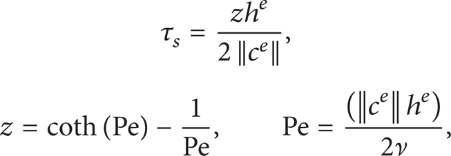
where h e , c e , and Pe denote the characteristic element size, the convection velocity in the element center, and the element Peclet number, respectively. The velocity and the pressure are interpolated by the linear shape function:

where u iI and p I are the nodal quantities of u i and p at node I, and Φ I denotes the shape function of the finite element. Multiplying (6)–(9) by test functions and integrating over the computational domain, and adding the SUPG term, the discrete matrix equations of the four steps can be obtained as follows:

where
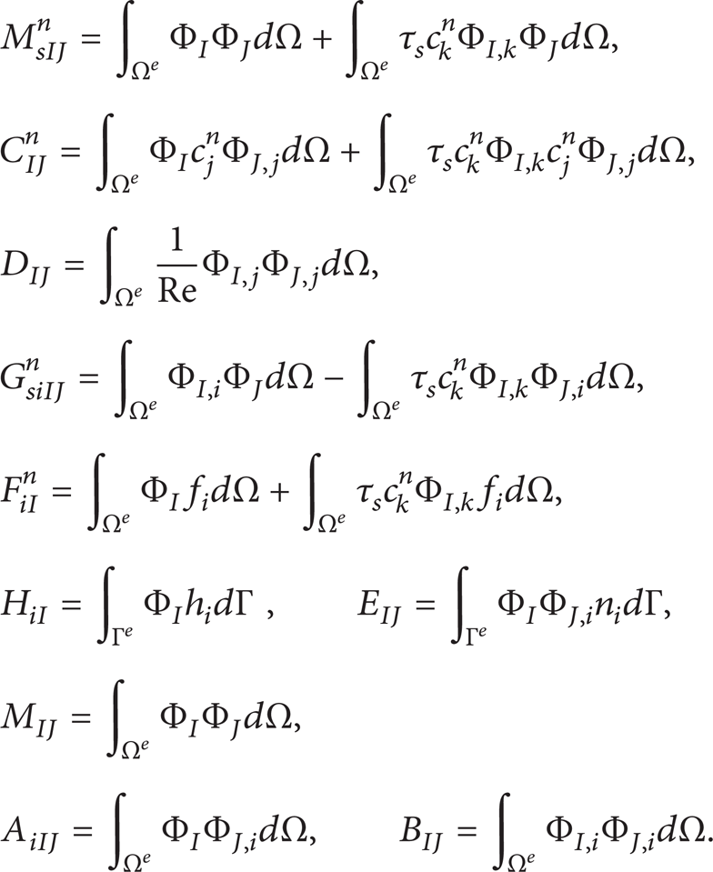
In (13), the boundary integrations are replaced by the enforcement of the boundary conditions (5) on the boundaries of the computation domain.
2.2. Dynamic Equations of the Cylinders and Mesh Moving Scheme
The motion equations of the vibrating cylinders with two degrees of freedom are modeled by a mass-spring-damper system as follows:
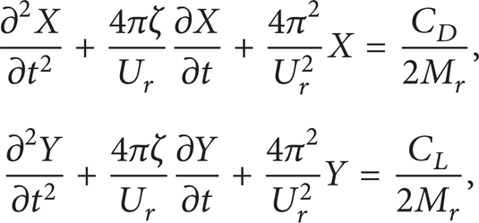
where X and Y represent the in-line and transverse displacements of the cylinder, respectively; ζ is the structural damping ratio; M r is the mass ratio, defined by
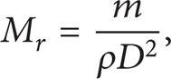
where m is the cylinder mass of the per unit length and ρ is the fluid density. C D and C L are the drag and lift coefficients, respectively, and they are computed by

where F D and F L are the drag and lift forces acting on the cylinder, respectively. The fluid forces are calculated by integrating the pressure and viscous stress on the surface of the cylinder. The reduced velocity U r is defined as

where f n is the structural natural frequency. The temporal integration of (14) is carried out numerically by the Newmark-β algorithm.
To accommodate the cylinder motion, the nodal displacements of the FEM mesh are calculated based on the boundary-value problem [21]:
where S i denotes the displacement component of the node in the x i -direction and τ is a parameter which controls the mesh deformation. In order to avoid excessive deformation of the near wall elements, the parameter τ in an element is set to be

where Δ e , Δmin, and Δmax represent the areas of the current, the largest, and smallest elements in the mesh, respectively. Γ m and Γ f are the moving and fixed portions of the boundary, respectively; g i is the prescribed mesh displacement component on Γ m . By specifying the displacements at all the boundaries, (18) is solved by the Galerkin FEM.
2.3. Fluid-Structure Interaction Procedure
The resolution of the fluid-structure interaction (FSI) problem can be conducted relatively easily by using a staggered algorithm [22]. The main procedure can be described as follows. (i) Initialize the fluid field on the initial mesh; (ii) calculate the hydrodynamic force coefficients of the cylinders by solving (16); (iii) solve (14) to get the displacements and velocities of the cylinders; (iv) renew the mesh field based on (18); (v) equations (12) are solved to obtain the fluid velocities and pressure on the new mesh; (vi) go to step; (ii) continue looping through these steps until the time limit for the computation is reached. The in-house computational code written by Fortran 90 is developed based on the algorithm mentioned above.
3. Computational Details
3.1. Flow Domain and Boundary Conditions
The geometry configuration and boundary conditions for a typical case of α = 0° are shown in Figure 2. The entire computational domain is defined as Ω = [– 30D, 70D] × [– 30D, 30D]. A Dirichlet boundary condition is applied on the inlet boundary as u1 = U∞ and u2 = 0, while, at the outlet, the conditions are ∂ u i /∂ x = 0 and p = 0. A no-slip condition is imposed upon the surface of the cylinders. The lateral boundaries have a slip condition of ∂ u1/∂ y = 0 and u2 = 0. Numerical simulations for the VIV of three cylinders are initialized from the solution of the flow over the stationary counterpart. For reference and comparison, the instantaneous vorticity fields of the flow over the stationary system at Re = 150 are shown in Figure 3.

VIV of three cylinders in equilateral-triangle arrangement at α = 0°: schematic diagram of the computational domain and boundary conditions.

Vorticity contours of the flow past three stationary cylinders at different flow incidence angles: (a) α = 0°, (b) α = 30°, and (c) α = 60°.
3.2. Mesh Resolution Study
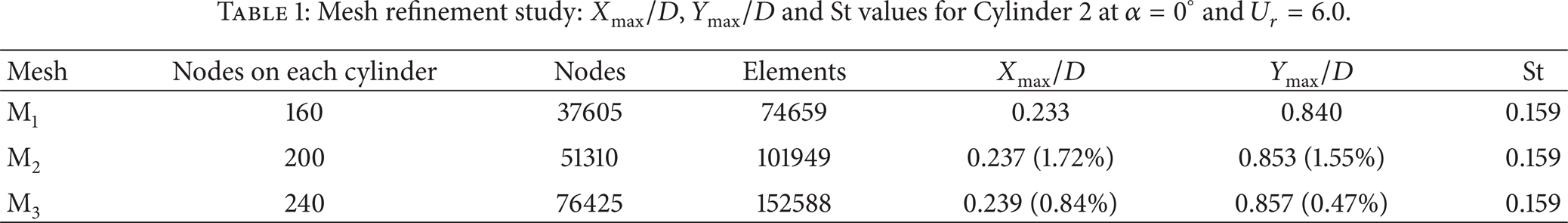
To ensure the mesh independency, three different meshes (named as M1, M2, and M3) have been considered for the mesh refinement study in the typical case of α = 0° and U r = 6.0. During the refinement, the time steps of Δt = 0.005, 0.002, and 0.001 are used, respectively, for meshes M1, M2 and M3. The mesh parameters and the computed values for Cylinder 2 are given in Table 1, along with the percentage differences. In this table, Xmax/D and Ymax/D are the nondimensional maximum vibration amplitudes in the in-line and transverse directions, respectively, and St represents the vortex shedding frequency. It is found that the maximum difference of 1.72% occurs in the value of Xmax/D from M1 to M2, while the maximum change is reduced to only 0.84% from M2 to M3. These results indicate that M2 with a time step of Δt = 0.002 and 200 nodes on each cylinder surface can provide acceptable temporal and spatial resolutions. The entire finite element mesh for M2, which consists of 101949 triangle elements and 51310 nodes, is shown in Figure 4.
Mesh refinement study: Xmax/D, Ymax/D and St values for Cylinder 2 at α = 0° and U r = 6.0.

The entire computational mesh for VIV of three cylinders in equilateral-triangle arrangement at α = 0°.
3.3. Code Validation Test
The finite element code is verified by applying it to the numerical simulation of VIV of a single cylinder with one degree of freedom (only transverse). Figure 5 shows the maximum amplitude response against the reduced velocity, along with the available solutions from the literature [5, 13, 23]. All numerical results are based on the same flow and structural parameters (Re = 150, M r = 2.0 and ζ = 0.0). It is shown that there is an excellent agreement between the present and previous results. The resonant region with the maximum vibrations of 0.38 ≤ Ymax/D ≤ 0.57 is observed in the simulations when 4.0 ≤ U r ≤ 7.0. All of the response curves reach the peak amplitude at the same reduced velocity of U r = 4.0. The comparisons indicate that our numerical method can provide satisfactory results for the VIV problem.
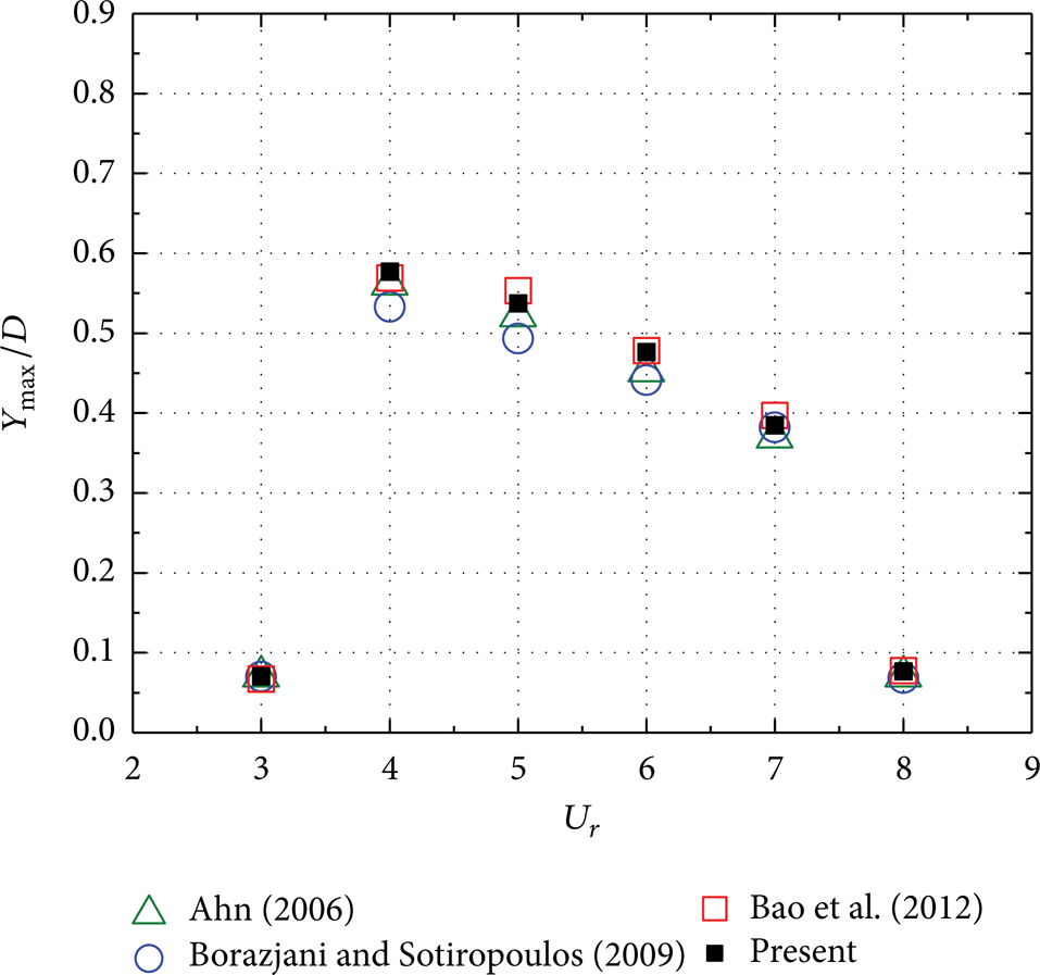
Comparisons of maximum vibration amplitude for the case of the VIV of a single cylinder at Re = 150.
4. Results and Discussion
4.1. VIV of Three Cylinders at α = 0°
Figure 6 shows the variations of the vortex shedding frequencies of three cylinders in equilateral-triangle arrangement with different U r at α = 0°. The variations of the structural natural frequency f n and vortex shedding frequency of a single vibrating cylinder are also shown in Figure 6. It can be found that the synchronization or lock-in for three cylinders occurs in the same range of 4 ≤ U r ≤ 8, which is wider than that for a single cylinder (4 ≤ U r ≤ 7). Here, noted that at U r = 4, the vortex shedding frequencies do not exactly match the f n , and there is a slight detuning, that is, “soft” lock-in. “Soft” lock-in has been previously reported for a single cylinder [24, 25] and has also been observed for two tandem or staggered cylinders [5, 9, 10, 26]. As stated by Mittal and Kumar [26], this is one of the physical mechanisms through which the nonlinear oscillator self-limits its vibration amplitude. Another interesting observation is that the vortex shedding frequencies of three cylinders are identical at all reduced velocities examined. Bao et al. [18] found a similar behavior for the stationary counterpart. This can be attributed to the synchronization between the wake interference and the vortex shedding from the cylinders. Beyond the lock-in resonance regime (U r ≥ 9), the vortex shedding frequencies of three vibrating cylinders approach that of the stationary counterpart (0.168) with the vibration amplitude being reduced; it is also noted that the vortex shedding frequencies of the single cylinder are slightly larger than those of the three cylinders.

Variations of the vortex shedding frequencies of three cylinders versus the reduced velocity at α = 0°.
Figure 7 shows the maximum vibration amplitudes of three cylinders in the transverse and in-line directions with various U r at α = 0°. The response of a single cylinder is also included in the figure for comparison. It is found that the vibration responses of the downstream Cylinders 2 and 3 are identical with each other in all conditions, due to their symmetric flow configuration. From Figure 7(a), it is seen that all three cylinders experience large amplitude transverse vibrations within 4 ≤ U r ≤ 8, caused by the lock-in resonance. The vibration responses of Cylinders 2 and 3 subjected to wake interference are larger than that of the upstream Cylinder 1 or the single cylinder. The peak amplitude of transverse vibration is about 0.853D for Cylinders 2 and 3 while it is 0.653D for Cylinder 1 and 0.631D for the single cylinder. The vibration amplitudes of Cylinders 2 and 3 are still significant even if the U r is outside the lock-in regime, and they are greater than 0.2D when 9 ≤ U r ≤ 12. In addition, the presence of the downstream cylinders has some effect on the upstream one. For example, the upstream Cylinder 1 experiences larger amplitude vibrations in the U r range of 5 ≤ U r ≤ 8 compared to the single cylinder. As shown in Figure 7(b), the vibration amplitudes in the in-line direction are much smaller than those in the transverse direction shown in Figure 7(a). The in-line vibration amplitudes of Cylinder 1 are qualitatively similar to those of the single cylinder. However, the in-line responses of Cylinders 2 and 3 are significantly larger compared to those of the single cylinder within the lock-in range of 4 ≤ U r ≤ 8, and the peak amplitude observed is 0.237D at U r = 6.
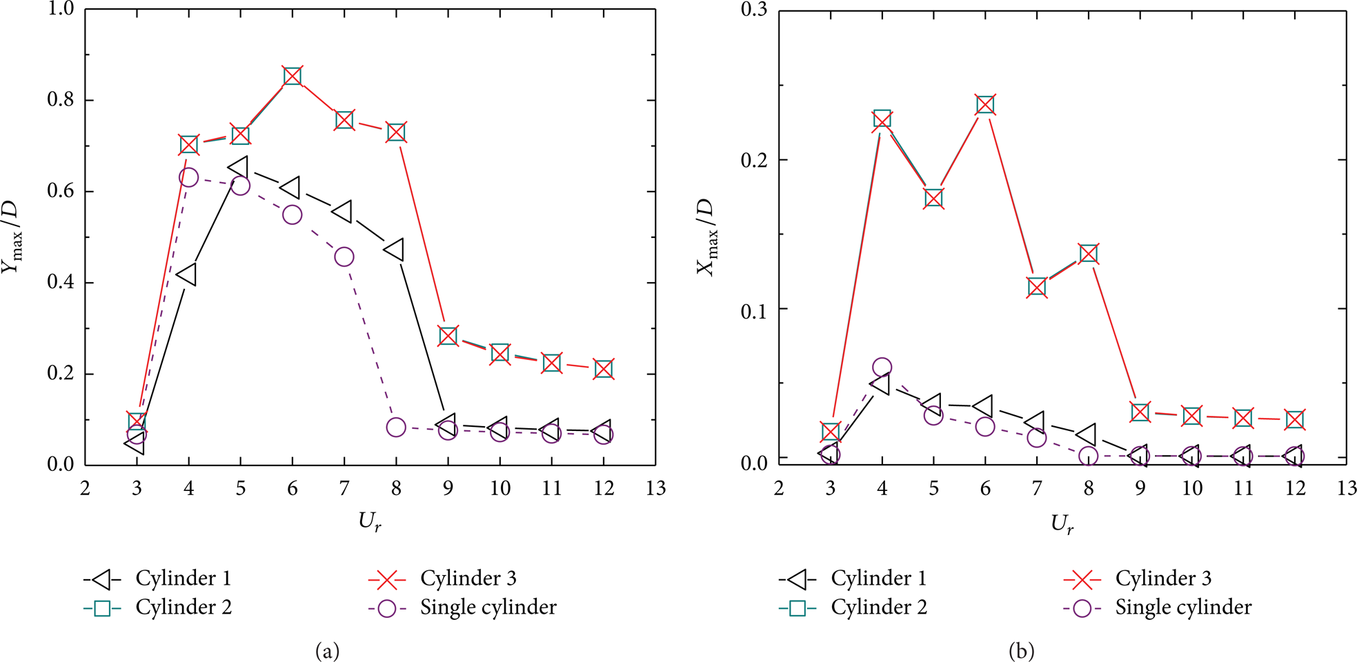
Maximum vibration amplitudes of three cylinders as a function of the reduced velocity at α = 0°: (a) transverse amplitude and (b) in-line amplitude.
The coupled transverse and in-line vibrations of a single cylinder typically present a figure-eight pattern because the vibration frequency in the in-line direction is twice that in the transverse direction [9]. This behavior is also observed for the upstream Cylinder 1 in the case of three cylinders at α = 0°. Figure 8 shows the Lissajous figures of the motion trajectories for the cylinders versus U r . It can be observed that, except for the case of U r = 4 where Cylinder 1 moves in a messy irregular trajectory, most of the motions present a regular figure-eight path. In contrast, the motions of Cylinders 2 and 3 show a very different behavior and their trajectories exhibit considerable variation with U r . At lower U r = 3, the two cylinders move in inclined figure-eight paths. During the lock-in regime, the motion trajectories are either in fairly irregular shapes or in inclined oval shapes. As U r increases beyond the lock-in regime, the trajectories exhibit vertical oval shapes. These oval motion trajectories imply that the vibration frequencies for Cylinder 2 or 3 in the transverse and in-line directions are the same but there is a certain phase difference between the two vibrations.

Lissajous figures of the trajectories for three cylinders versus the reduced velocity at α = 0°: (a) U r = 3, (b) U r = 4, (c) U r = 5, (d) U r = 6, (e) U r = 7, (f) U r = 8, (g) U r = 9, (h) U r = 10, and (i) U r = 12. In the plot, the black, cyan, and red lines represent the trajectories of Cylinder 1, 2, and 3, respectively.
Figure 9 shows the time histories of the transverse and in-line displacements of three cylinders at U r = 6 and U r = 8. At U r = 6, Cylinders 2 and 3 undergo large amplitude vibrations. Beating is observed from the time histories of both transverse and in-line responses of the cylinders, resulting in unclosed Lissajous figures as shown in Figure 8(d). At U r = 8, constant periodic vibrations are observed in the time histories of the responses of three cylinders, and these are typical of the responses seen at many other U r .

Displacement time histories of three cylinders at U r = 6 and 8. In the plot, the black and green lines represent the transverse and in-line displacements, respectively.
Figure 10 shows the instantaneous vorticity fields for the fully developed flow with different U r at α = 0°. At U r = 3, a nearly in-phase synchronized vortex shedding is developed behind the three cylinders. The vortices from upstream Cylinder 1 pass though the gap between downstream Cylinders 2 and 3 and merge with those from inner sides of the downstream cylinders in the far wake. It is also noted that the vortices from the outer sides of the downstream cylinders do not take part in the merging process. This wake pattern is similar to that for the stationary counterpart shown in Figure 3(a). Within the lock-in regime of 4 ≤ U r ≤ 8, because of large amplitude vibrations of the cylinders, the vortices shedding from them appear to be not in-phase synchronized. The vortices from the upstream cylinder can even impinge on the inner sides of the downstream cylinders and the vortex-cylinder interactions become more active. An unstable wake is observed at 4 ≤ U r ≤ 6, which is associated with the unclosed trajectories shown in Figure 8; as the reduced velocity increases up to U r = 7.0–8.0, a regular wake is recovered behind the cylinders. Beyond the lock-in regime (U r = 9–10), all cylinders return to the in-phase synchronized vortex shedding; however, with the vibration amplitude being reduced, the downstream wake becomes significantly narrow.

Vorticity fields for fully developed flow with different reduced velocities at α = 0°.
4.2. VIV of Three Cylinders at α = 30°
Figure 11 shows the variations of the vortex shedding frequencies of three cylinders with different U r at α = 30°. Similar to the case of α = 0°, the lock-in for three cylinders at α = 30° also occurs in the same range of 4 ≤ U r ≤ 8. At U r = 4, the vortex shedding frequency of Cylinder 3 is much closer to the f n than those of the other cylinders; in addition, it is significantly larger compared to those of Cylinders 1 and 2 outside the lock-in range. For tandem Cylinders 1 and 2, their vortex shedding frequencies are identical with each other at all U r , which can be attributed to the synchronization between the flow impingement and the vortex shedding from the downstream cylinder. The frequency characteristics of Cylinders 1 and 2 in this case show a reasonable agreement with the available numerical investigations on two tandem cylinders [9, 10].

Variations of the vortex shedding frequencies of three cylinders versus the reduced velocity at α = 30°.
Figure 12 shows the maximum transverse and in-line vibration amplitudes of three cylinders with various U r at α = 30°. From Figure 12(a), it is seen that Cylinders 1 and 3 experience significant vibrations in the transverse direction within the lock-in range of 4 ≤ U r ≤ 8, and their peak amplitudes are comparable to that of the single cylinder. However, Cylinder 2 exhibits a completely different response. The peak amplitude of Cylinder 2 shifts to a more higher reduced velocity (U r = 8) compared to other cylinders and reaches a relatively high value of 1.071D, which is approximately twice those of the other cylinders. The transverse response of Cylinder 2 remains at a high level even at the highest reduced velocity (U r = 12). As shown in Figure 12(b), the in-line responses of Cylinders 1 and 3 are qualitatively similar to that of the single cylinder. For Cylinder 2, the peak amplitudes show much larger compared to the single cylinder, and the primary peak at U r = 6 reaches a level as high as 0.614D. Some local peaks are observed at both sub- and super-harmonics of f n corresponding to U r = 6. In existing numerical simulations of VIV of two tandem cylinders [5, 9, 10, 13], the response of the downstream cylinder exhibits similar dynamic characteristics to the present results for Cylinder 2.

Maximum vibration amplitudes of three cylinders as a function of reduced velocity at α = 30°: (a) transverse amplitude and (b) in-line amplitude.
Figure 13 shows the Lissajous figures of the trajectories for three cylinders with some representative U r at α = 30°. In most cases, the three cylinders move along unclosed trajectories, which are particularly apparent for downstream Cylinder 2 due to the high disturbance in the wake of upstream cylinder. Closed motions only occur at U r = 7 and 8 where the vortex shedding frequencies of three cylinders collapse exactly upon the natural frequency f n , and the trajectories exhibit inclined figure-eight patterns. The asymmetric feature of the motion patterns can be explained by the asymmetric mean flow with respect to the free stream direction.

Lissajous figures of the trajectories for three cylinders at some representative reduced velocities at α = 30°: (a) U r = 3, (b) U r = 5, (c) U r = 6, (d) U r = 7, (e) U r = 8, and (f) U r = 9. In the plot, the black, cyan, and red lines represent the trajectories of Cylinder 1, 2, and 3, respectively.
Figure 14 shows the instantaneous vorticity contours of the flow with some typical U r at α = 30°. The vortices shedding from upstream Cylinder 1 always impinge on downstream Cylinder 2. A near-independent vortex street is developed behind Cylinder 3 and interacts with that behind the two tandem cylinders. It is worth noting that at U r = 7 and 8, the vortices shedding from the inner sides of the cylinders become weaker and weaker as they move further downstream; therefore, a two-row vortex structure forms in the far wake.

Vorticity fields for fully developed flow with various reduced velocities at α = 30°.
4.3. VIV of Three Cylinders at α = 60°
Figure 15 shows the variations of the vortex shedding frequencies of three cylinders with different U r at α = 60°. As seen in Figure 15, for upstream Cylinders 1 and 3, the lock-in regime is the same as that for the single cylinder. At the onset of the lock-in, that is, U r = 4, the vortex shedding frequencies of Cylinders 1 and 3 are much closer to the f n than that of the single cylinder or Cylinder 2; with increasing U r , their vortex shedding frequencies collapse onto the f n until reaching the end of the lock-in at U r = 7. For downstream Cylinder 2, the lock-in occurs in a wider range of 4 ≤ U r ≤ 8 compared to the single cylinder, which indicates that the vortex shedding of the downstream cylinder is affected by the upstream side-by-side cylinders.

Variations of the vortex shedding frequencies of three cylinders versus the reduced velocity at α = 60°.
Figure 16 shows the maximum vibration amplitudes of three cylinders with various U r at α = 60°. The responses of upstream Cylinders 1 and 3 are the same throughout the entire range of U r , due to their symmetric flow configuration. From Figure 16(a), it is observed that the maximum transverse amplitudes of Cylinders 1 and 3 are very similar to that of the single cylinder, which indicates that the transverse responses of upstream cylinders are less affected by the downstream cylinder. In contrast, the downstream Cylinder 2 shows larger amplitude vibrations over the entire range of U r (especially for the lock-in resonance range of 4 ≤ U r ≤ 8) due to the wake interference and achieves the peak amplitude (0.818D) at U r = 7. As shown in Figure 16(b), the maximum in-line amplitudes of Cylinders 1 and 3 are slightly larger than those of the single cylinder, but still less than 0.1D. For the downstream Cylinder 2, significant in-line responses are triggered in the range of 4 ≤ U r ≤ 8, corresponding to the large amplitude transverse vibrations. At U r = 6, the in-line maximum amplitude reaches a level as high as 0.437D, which is one order larger than that of the single cylinder. From Figure 16, it is seen that the variation of the vibration amplitude of Cylinder 2 in the in-line direction is more significant than that in the transverse direction.

Maximum vibration amplitudes of three cylinders as a function of reduced velocity at α = 60°: (a) transverse amplitude and (b) in-line amplitude.
For the equilateral-triangle arrangement at α = 60°, the motion trajectories of upstream Cylinders 1 and 3 usually present unclosed figure-eight patterns, while the motion of Cylinder 2 is irregular mostly. Figure 17 shows the Lissajous figures of the trajectories for three cylinders with some representative U r . It can be seen clearly that Cylinder 2 experiences a very complex vibration, and the maximum amplitudes in transverse and in-line directions are significantly larger than those of the other two cylinders. The irregularity of the motion of Cylinder 2 implies that the wake interference of the upstream cylinders induces complex dynamic response of the downstream cylinder.
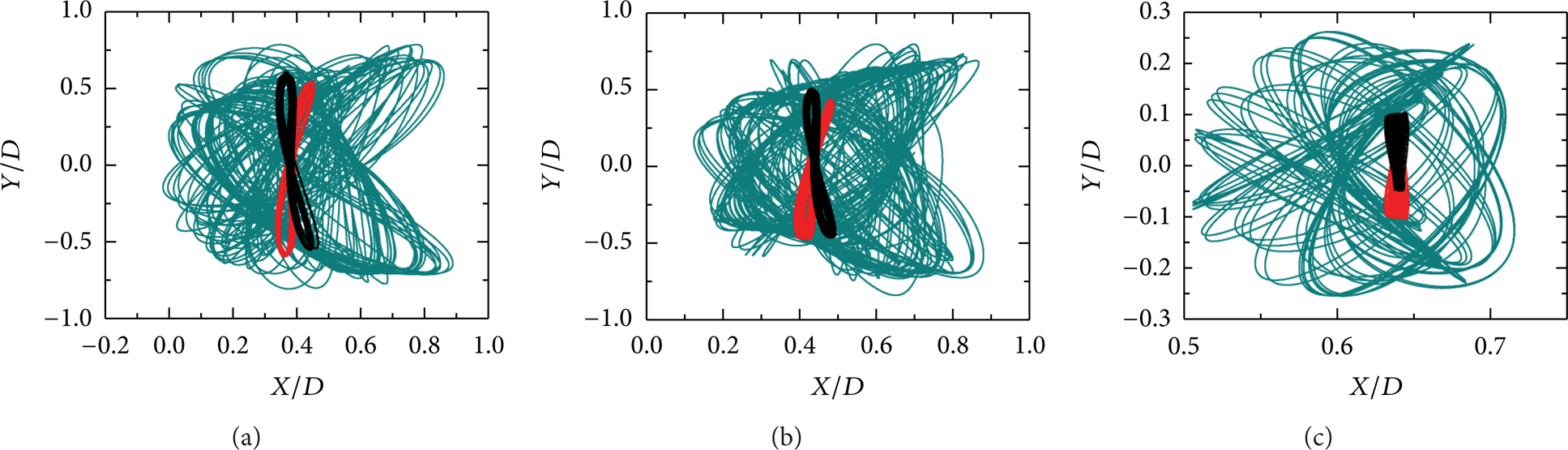
Lissajous figures of the trajectories for three cylinders with some representative reduced velocities at α = 60°: (a) U r = 6, (b) U r = 7, and (c) U r = 9. In the plot, the black, cyan, and red lines represent the trajectories of Cylinder 1, 2, and 3, respectively.
Figure 18 shows the instantaneous vorticity fields with some typical U r at α = 60°. It is observed that the vortices shedding from the upstream cylinders pass through the up and down sides of the downstream cylinder and interact with those shedding from downstream one, making the wake flow more disordered. The reduced velocity has some effect on the flow pattern: at U r = 3 and 4, different from the flow pattern of the stationary counterpart shown in Figure 3(c) where the vortex shedding in antiphase is formed behind the upstream side-by-side cylinders, a nearly in-phase vortex shedding occurs. However, when U r ≥ 5, the antiphase vortex shedding is recovered at the lee sides of the upstream cylinders.

Vorticity fields for fully developed flow with various reduced velocities at α = 60°.
4.4. Comparisons of Vibration Responses for Three Cylinders at Different α
The lock-in region and peak vibration amplitudes of three cylinders at three typical α are listed in Table 2, as well as those for a single cylinder. It is found that the lock-in range for all cylinders appears to be less sensitive to the flow incidence angle. The peak amplitudes of Cylinder 1 in both directions are always close to those of the single cylinder, while the peak amplitudes of Cylinder 2 become significantly larger. It is worth noting that the vibration amplitudes of 1.071D and 0.614D for Cylinder 2 at α = 30° are the maximum values of the transverse and in-line responses, respectively, for all simulated cases in this study. The vigorous vibrations of Cylinder 2 can be explained by the strong wake flow impingement on the cylinder.
Lock-in range and peak vibration amplitudes for the three cylinders at different incidence angles and a single cylinder. In this table, the bolded values 1.071 and 0.614 are the maximum transverse and in-line amplitudes, respectively, for all examined cases.

5. Conclusions
Vortex-induced vibrations of three cylinders in equilateral-triangle arrangement at three flow incidence angles (α = 0°, 30°, and 60°) have been investigated numerically at Re = 150. The gap spacing between the cylinders is set as 4D. A low mass ratio of M r = 2.0 and a zero value of damping coefficient are assigned to be the structural parameters. The four-step fractional FEM is employed to solve the governing equations of fluid flow in two dimensions with varying reduced velocities from 3 to 12. Main conclusions are summarized as follows.
At α = 0° and 30°, the lock-in for three cylinders occurs in the same range of 4 ≤ U r ≤ 8, which is wider than that for a single cylinder (4 ≤ U r ≤ 7). At α = 60°, the lock-in range for the two upstream cylinders is 4 ≤ U r ≤ 7, while it is 4 ≤ U r ≤ 8 for the downstream cylinder. For each α, within the lock-in range the cylinders undergo large amplitude resonant vibrations, especially for the downstream cylinder (or cylinders). At α = 30°, the vibration amplitudes of 1.071D and 0.614D for the downstream cylinder are the maximum values of the transverse and in-line responses, respectively, among all cases examined in this paper.
At α = 0°, the trajectories of the upstream cylinder generally present a typical figure-eight pattern similar to that of the single cylinder. However, the two downstream cylinders move along oval trajectories at many U r , indicating that the transverse and in-line vibrations have the same frequency but with a phase difference; the vortices shedding from the three cylinders are found to be nearly in-phase synchronized except within the lock-in range. At α = 30°, closed motions for the three cylinders only occur at U r = 7 and 8 where the vortex shedding frequencies of the cylinders are exactly equal to the structural natural frequency, and their trajectories exhibit inclined figure-eight patterns due to the asymmetric mean flow. At α = 60°, the vibration of the downstream cylinder is irregular mostly because the two upstream cylinders have complicated wake interferences on the downstream cylinder; within the range of 4 ≤ U r ≤ 5, it is observed that the shedding vortices from the upstream cylinders change from in-phase synchronized pattern to antiphase synchronized pattern.
Footnotes
Acknowledgment
Financial support provided by the National Natural Science Foundation of China through Grant no. 51179101 is acknowledged.