
Abstract
The packing of granular materials is a basic and important problem in geomechanics. An approach, which generates dense packing of spheres confined in cylindrical and cuboidal containers in three steps, is introduced in this work. A loose packing structure is first generated by means of a reference lattice method. Then a dense packing structure is obtained in a container by simulating dropping of particles under gravitational forces. Furthermore, a scheme that makes the bottom boundary fluctuate up and down was applied to obtain more denser packing. The discrete element method (DEM) was employed to simulate the interactions between particle-particle and particle-boundary during the particles' motions. Finally, two cases were presented to indicate the validity of the method proposed in this work.
1. Introduction
The compaction of granular materials is a current subject of keen interest, which is widely used in sciences and engineering; for example, a compaction structure of granular materials can be used to model the structure of granular media, liquids, living cells, glasses, and random media. The spheres packing problem has its roots in geometry and number theory (it is part of Hilbert's 18th problem) [1]. Finding sphere packing with maximal density ais important to most unsolved problems with many applications.
The bulk density of a packed assembly is characterized by the packing fraction, which is the ratio of the particles' volume to the total occupied volume of the system [2]. A collection of uniformly sized balls in Euclidean 3-space is called a packing if no two balls have a common interior point. The packing fraction of equal spheres' packing in three dimensions cannot exceed that of the face-centered cubic packing,
At present, many methods have been developed to obtain higher density of particle packing. These methods can be divided into four types: geometric method (GM), discrete element method (DEM), combined geometry and particle motion (CGPM), and Monte Carlo method (MC). In the GM, the particles' motions are not considered and a dense packing was formed by a purely geometrical computation; for example, Place and Mora, Delarue and Jeulin [4, 5] randomly placed a given number of particles within 3D space and a dense packing was obtained by filling the remaining voids with particles. In the DEM, the interaction forces between particles in contact and between particles and boundaries were calculated and the Newtonian second law was employed to describe particles' motions; for example, Siiriä and Yliruusi used DEM to simulate the particles' packing formation [6–8]. In the CGPM, the geometrical method was not only used, but also the particles' motions were considered, for example, Lubachevsky and Stillinger's compression algorithm [9–11], and the spheres grow in size during the process of the simulation at a certain expansion rate until a final state with diverging collision rate is reached. In the Monte Carlo method, a loose particle packing structure is first generated. Then a slight random displacement is exerted on each particle. Furthermore, the new configuration can be accepted or not by identifying overlap and variety of potential energy. Finally, a dense packing can be reached by repeating the above course many times [12]. These above mentioned methods mainly focus on reaching the highest packing density instead of describing real mechanical characteristics during the course of forming dense packing.
In this work, the objective is to generate a dense packing structure of particles to model practical dense packing, for instance, structure of concrete, packing of grain, soil, and sand, and so forth, instead of only obtaining the highest packing density. Therefore, the mechanical characteristics of forming dense packing are considered in our study. The Discrete Element Method (DEM) is employed to simulate particles' packing confined in container (cylindrical container and cuboidal container). A loose structure was first generated. Then the dropping of particles onto the bottom of the container due to gravity is simulated. Furthermore, the bottom boundary of the container was fluctuated up and down to reach a more dense packing.
2. Initial Loose Packing
A loose packing structure must be generated in order to simulate the process of particle packing under gravitational forces. Loose packing means that there is no overlap existing between particle and its neighbors or between particle and boundaries. The objective is to avoid interactions among particles and between particles and boundaries at initial state. A simple scheme has been applied to generate loose packing. First, a reference cuboid whose projection in xoy plane is a square has been constructed within container. The symmetrical axis of reference cuboid is the same as that of container. For a cylindrical container, the reference cuboid has the maximal size when it is inscribed to the container (see Figure 1(a)), but for cuboidal container, the maximal size of reference cuboid is the same as that of the container within the range of the container height (see Figure 1(b)). The size of the reference cuboid does not havea determinate value for a certain container because the length of its section must be integral times of the size of lattice. The height of the reference cuboid is determined by the number of particles. Secondly, the reference cuboid is partitioned using cubic lattice. The cubic lattices are regarded as reference lattice for generating coordinates of spheres' centers. The size of lattice is determined by the sizes of particles and container. Finally, a random point is selected within each cubic lattice and the point is regarded as a particle's center. It should be noted that the random point within a cubic lattice must meet the request of no existing intersection between particle's surface and lattice's faces.
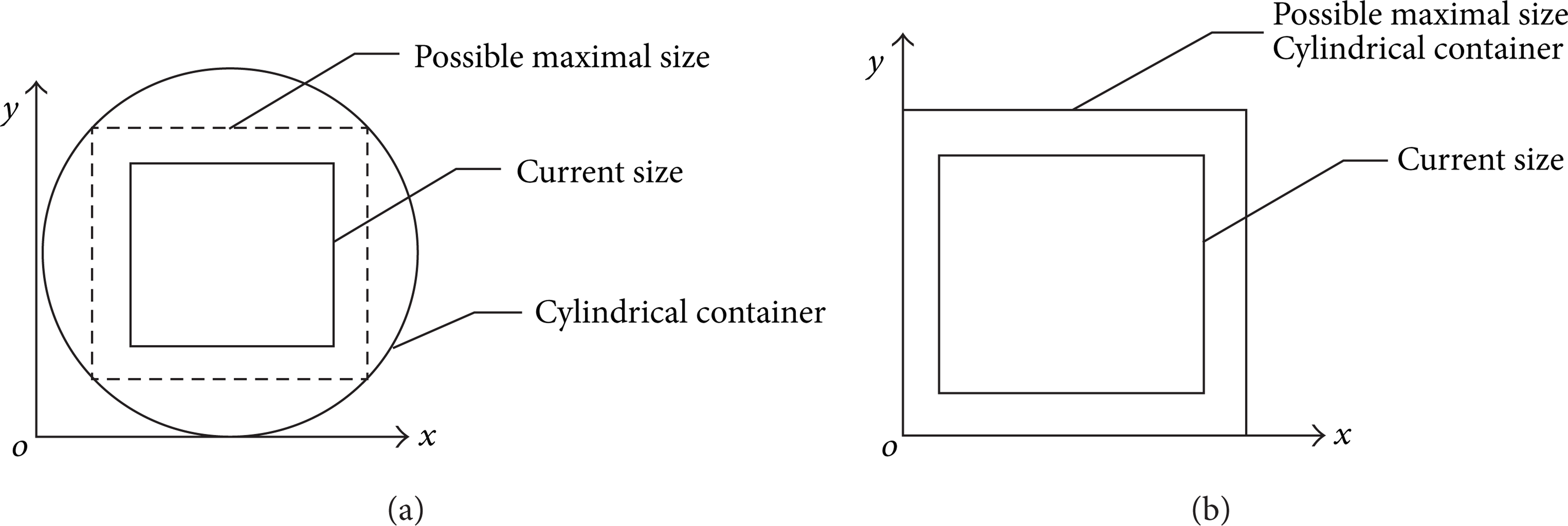
The sketch map of reference cuboid for cylindrical (a) and cuboidal (b) container, respectively.
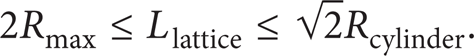
Let N p represent the number of particles; rmax and rmin denote the maximal and minimal radius of the particles; Rcylinder and Hcylinder are the radius and height of cylinder; the size of the cuboidal container is Lcuboid × Lcuboid × Hcuboid; and the size of the reference cuboid is L r × L r × H r . For the cylindrical container, the size of reference lattice is limited by the following equation:
The size of reference cuboid for cylindrical container is
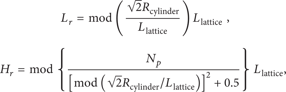
where mod means remaining integral part of the result.
For the cuboidal container, the size of reference lattice is

The size of reference cuboid for cuboidal container is

3. Mechanical Model
In the current study, the Discrete Element Method (DEM) [13] has been employed to simulate the interactions among particles and between particles and boundaries. DEM is a finite difference scheme. It is used to study assemblies of individual particles. By monitoring the interaction between particles, the behavior of the material is known.
3.1. Contact Forces
The sketch map of contact model is shown in Figure 2.

The sketch map of calculating contact force ((a) two particles in contact; (b) the mechanical model of contact. N-normal direction, T-tangential direction).
The normal contact force F N and shear contact force F T can be expressed by
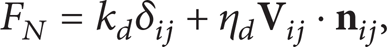

where k
d
, kτ represent the normal and shear spring constant; η
d
, ητ are the normal and shear damping coefficient due to the dissipative force;

where

where
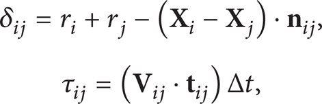
where Δt is the time step.
The shear force should be modified because of frictional effects:
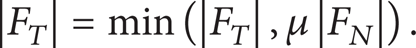
In (10), the sign obtained from (6) is preserved. In (10), μ is the coefficient according to Coulomb's frictional theory.
3.2. Particles Motions
The particles' motions are simulated using Newton's second law; that is,
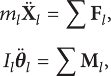
where m
l
, I
l
represent the mass and moment of inertia of particle l, l = 1, 2, …, N
p
,
3.3. Oscillations of Bottom Boundary
To improve the volume fraction, the oscillations of bottom boundary are applied after a dense packing formation under gravity forces. A sinusoidal function has been used to describe increment of containers' bottom boundaries displacements; see the following equation:

where ΔU(t) is the increment of bottom boundary displacement, A is the amplitude of increment, NΔt is the period of oscillation, N is the number of time step within a period, and t is the current time. The increment of displacement must be small enough in each time step to keep stability of calculation. The central coordinates of the bottom of containers vary with calculation time; that is,

where
4. Two Cases
A computer program has been developed using the above-mentioned algorithm. To verify validity of the method proposed in this work, two cases are introduced for cylindrical and cuboidal containers, respectively.
4.1. Initial Loose Packing
The parameters used in initial loose packing simulation are listed in Table 1. The configurations of loose packing structures are shown in Figure 3.
Parameters used in the simulation of initial loose packing.


Initial loose packing configuration for cylindrical (a) and cuboidal (b) container, respectively.
4.2. Dense Packing under Gravity Forces
The dense packing under gravity forces process is simulated using the methods described in Section 3. Parameters used in the simulation are listed in Table 2. The simulation results are shown in Figures 4 and 5.
Parameters used in dense packing simulation.


The dropping process of particles under gravity forces within a cylindrical container ((a), (b), (c) and (d) are the configuration at 0.2 s, 0.35 s, 0.65 s, and 1 s, resp.).

The dropping process of particles under gravity forces within a cuboidal container ((a), (b), (c), and (d) are the configuration at 0.2 s, 0.35 s, 0.65 s, and 1 s, resp.).
4.3. Dense Packing Induced by Oscillations of Containers
The packing fraction has been calculated in the oscillating process. The sum of particles volume is a constant when oscillating containers, but the volume occupied by particles within the container varies with the container oscillating. So, the packing fraction is calculated approximately for the cuboidal container as follows:

where V p is the sum of particles volume, a is the side length of the bottom boundary, z pmax is the maximal z coordinate of particles during particles motions, and r is the corresponding radius of the particle. For cylindrical container, replace a2 byπRcylinder2.
Figures 6(a), 6(b), 6(c), and 6(d) are the simulation results before and after container oscillations for cylindrical and cuboidal container, respectively. In addition, the dense packings of particles with four kinds of grain size distribution were also simulated for cylindrical and cuboidal container, respectively, as shown in Figure 7. Figure 7 shows that the particles with smaller sizes can reach a larger volume fraction both for cylindrical and cuboidal containers. Furthermore, the effects of amplitude of oscillation on volume in the case of keeping other factors the same were analyzed. An optimal oscillation amplitude exists as shown in Figure 8. The frequency of oscillation was also analyzed in this work. In some values of oscillation frequency, the dense packing structure can reach a higher volume fraction. However, there is no definite relationship between oscillation frequency and the resulted volume fraction, as shown in Figure 9.

The dense packing of particles in cylindrical and cuboidal container before and after container oscillation ((a), (c) before container oscillation; (b), (d) after container oscillation).

The relationship between volume fraction and average size of particles.

The relationship between volume fraction and oscillation amplitude.

The relationship between volume fraction and oscillation frequency.
5. Conclusions and Discussions
The simulating results implicate that oscillation of container can significantly affect the packing density. However, different oscillation amplitudes and frequencies have different effects on packing density. For a given particles system, there exists an optimal amplitude of oscillation corresponding to the maximum volume fraction. But there is no definite relationship between the frequency of oscillation and the volume fraction.
The packing density from our simulation does not exceed that from the method in the view of pure geometry. The main reason lies that the mechanical behaviors of interactions between particles and between particles and boundaries was simulated such as motions, collisions, and frictions in condition of container oscillation.
It should be noted that there exists slight overlap in the final packing structure since the gravitational forces of particles have been considered in the simulation. However, the penetration depth is small enough (10−6 m in the simulation). Therefore, the effects of small penetration depth in particles on the packing structure can be ignored in the simulation.
Footnotes
Acknowledgment
This work was supported by the Grant from the National Natural Science Foundation of China (no. 51174076). This grant is gratefully acknowledged.