
Abstract
This work experimentally investigated the fluid flow and heat transfer characteristics of the pin-fin heat sink with the oscillating air flow. The oscillating air flow would be unstable in the passages among the fins due to the periodical change of flow rate. It might enhance the overall heat-transfer performance. At the present study, the pin-fin heat sinks with various fin heights were installed in the rectangular channel, resulting in different bypass clearances between the pin fins and the shroud of the test channel. The smoke flow visualizations for the oscillating-flow system were completed. The heat-transfer tests under the asymmetrically heated condition were performed to obtain the average Nusselt numbers. The smoke lines with obvious waves in the transverse direction were found in the results of the flow visualizations. By comparing to the steady flow system, there was about 20∼34% increment in the overall heat-transfer performance at the operating state without bypass clearance. However, if the bypass clearance was too big, the heat-exchange capacity of the oscillating flow was less than that of the steady flow. It demonstrates that the oscillating flow promotes the cooling performance of pin-fin heat sink at the non-bypass and specified bypass conditions.
1. Introduction
The heat dissipated from the electric equipments and the power machines is growing continuously. In order to protect these equipments and machines from being operated at the over high-temperature condition, the effective cooling system is necessary. Combining the finned heat sink with the steady flow of fixed flow rate is one of the simple and effective cooling technologies [1–6]. Besides, heat transfer in the oscillating flow has been a principal investigation area for past several decades. Oscillation-induced heat transport processes maintaining an effective heat transfer enhancement have been demonstrated [7–11]. Recently, the fluid flow and heat transfer characteristics of oscillating flow through porous media are explored [12–15]. All of these studies indicated that employing high amplitude and frequency of the oscillating flow would increase the heat transfer. It is because that the oscillating air flow would be unstable in the porous structure and increase the staying time of air through the porous media.
Based on the above-mentioned literature survey, the study of applying the oscillating flow through the pin-fin heat sink to enhance heat transfer is few. Therefore, this work will build a device to oscillate air flow and experimentally investigate the effect of the oscillating flow on the heat transfer enhancement of the finned heat sink with top bypass clearance.
2. Experimental Method
2.1. Experimental Setup
An experimental setup, as shown in Figure 1, was built for the investigations of the heat transfer and fluid flow characteristics. The experimental setup included the air-supplying equipment, the oscillating-flow-generating equipment, the test section, the data-acquiring equipment, the smoke generator, and the image-capturing equipment. The compressed air was generated by the 5HP air compressor firstly, then entered into an 800 L steel tank to reduce the flow impulse as well as flowed through the dryer and filter to remove the water and impurities, and finally passed through the flow controller to adjust the flow rate. Before entering into the test section of the finned heat sink, the air went through the oscillating-flow-generating equipment to become the oscillating flow. As shown in Figure 2, the oscillating-flow-generating equipment was made of a motor, a switching valve, and an inverter. By using the belt, the motor could drive the switching valve rotating in the pipe to reach the objective of opening and closing the air flow periodically. The test section, as shown in Figure 3, was a square chamber made of the Bakelite. An aluminum-alloy circular pin-fin heat sink was installed in the test section. Dimensions of the heat sink are shown in Figure 4. Three heights of the pin fins were employed, including 46, 30, and 20 mm. The spreader of the heat sink was adhered with the film heater by the grease with the high thermal conductivity. The other side of the film heater was adhered onto the upper shroud of the test section. Four T-T-30SLE T-Type thermocouples through the upper shroud were connected onto the film heater to measure the heated wall. The film heater was heated by the DC power supply. The data-acquiring equipment, including the YOKOGAWA MX100 data recorder and the personal computer, was used to record the steady-state temperature data. The criterion of the steady-state data was the change of the temperature within 0.2°C during 15 minutes.

Experimental setup.

Sketch map of oscillating-flow-generating device.

Dimensions of test section and positions of thermocouples (unit: mm).

Dimensions of finned heat sink with H f = 46 mm (unit: mm).
2.2. Data Reduction and Uncertainty Analysis
According to the estimation method of heat loss, the inlet and outlet of the test channel were sealed tightly by polystyrene. Due to lack of air from/into the test channel for heat exchange, the heat supplied by the film heater (Qin) was almost equal to the heat loss (Qloss) dispersed from the outer surfaces of test channel. When estimating the heat loss, it was required to input different heat quantities and record the wall temperatures (Tw) and ambient temperatures (T∞) when the system reached a steady state. Therefore, the relationship between the heat loss and (Tw – T∞) was obtained. The measured data was used to determine the relevant dimensionless parameters, including average Reynolds number (Re) and average Nusselt number (Nu):

where Uave is the average fluid velocity in the test section, Dh is the hydraulic diameter of the test section, Tw is the mean wall temperature, Tfb is the mean value of the air temperatures at the channel inlet/outlet ((Ti + To)/2), Qin is the total input heat, Qloss is the heat loss, and A is the surface area of heated wall.
The uncertainties of experimental results included the measurement and calculation deviations. The measurement deviation was caused by the errors of the instruments or manual reading, and the calculation deviation was formed by interactive operation of measured parameters. The uncertainties, analyzed by the method of Moffat [16], in average Reynolds number (Re) and average Nusselt number (Nu) were ±3.35% and ±6.96%.
3. Results and Discussion
Figure 5 displays the photos of flow visualizations. The operation condition was set as flow rate of 5 L/min and oscillating frequency of 2.5 Hz. The photos show clearly that the smoke flow was blown from the nozzle periodically. When the time was T s, a big amount of smoke was blown away at the exit of the nozzle. When the time marched to T + 0.2 s, the amount of blown smoke became very small. It demonstrates that the present oscillating-flow-generating equipment did work. At the present study, the periods of the oscillating flow were 0.4, 0.2, and 0.133 s separately for 2.5, 5, and 7.5 Hz oscillating frequency (f).
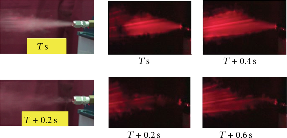
Photos of flow visualizations (Qflow = 5 L/min and f = 2.5 Hz).
Figures 6–8 depict the photos of flow visualization for the 20 mm height, 30 mm height and 46 mm height pin-fin heat sink, respectively. They separately display the test conditions with 26 mm, 16 mm, and none top bypass clearances. The operation condition was also set as flow rate of 5 L/min and oscillating frequency of 2.5 Hz. There were two characteristics in the smoke flow visualizations worthy to note. One was the remarkable transverse waves appearing at the streamlines. This flow characteristic could be observed from the videos of the smoke flow visualization clearly and was very different from that of the steady flow. The other was that the most smoke flow appeared at the passages with smaller flow resistance to leave from the exit of the test channel. It is the reason that so much amount of smoke flow went through the top clearance and bypassed pin fins to exit (as shown in Figures 6 and 7), especially for the 20 mm height pin fins with bigger top bypass clearance. The big amount of bypass air flow means the small amount of heat-exchange air flow, reducing the overall heat transfer capacity. Besides, as shown in Figure 8, the test section without any top bypass clearance formed vortices at the four corners, satisfying the rule of the fluid flow through the passages with the minimum flow resistance.

Photos of flow visualization for the 20 mm height pin fins. (a) Side view. (b) Top view (the middle section of bypass clearance). (c) Top view (the middle section of pin fins).

Photos of flow visualization for the 30 mm height pin fins. (a) Side view. (b) Top view (the middle section of bypass clearance). (c) Top view (the middle section of pin fins).

Photos of flow visualization for the 46 mm height pin fins. (a) Side view. (b) Top view (the middle section of pin fins).
Figure 9 depicts the relationship between Nu and Re. The test results indicate that the Nu values of the oscillating flow were higher than those of the steady flow. The heat-transfer enhancement by the oscillating flow was about 10∼34% for the cases with sufficiently small bypass clearance; it increased with the oscillating frequency. This phenomenon can be explained as follows. The oscillating-flow-generating equipment made the periodically changed flow rate. The air flow would be unstable in the passages among the fins due to the oscillation of flow rate, increasing the staying time of air through the fins. Therefore, the overall heat-transfer performance would be enhanced. Besides, the Nu values of the cases with the fin height of 46 mm (i.e., no bypass flow) were 2∼20% higher than those with the fin height of 30 mm. The difference of Nusselt number between these two kinds of cases was bigger when the average Reynolds number was smaller and the oscillating frequency was higher. It means the bypass effect was remarkable at those conditions. Finally, one can also find that the oscillating flow could not promote the heat transfer for the cases with the fin height of 20 mm; the Nu values of the oscillating flow were even lower than those of the steady flow obviously. It is because that the sufficiently big top clearance made more amount of the oscillating flow to bypass from the pin-fin array.

Relationship between Nu and Re. (a) H f = 46 mm. (b) H f = 30 mm. (c) H f = 20 mm.
Figure 10 shows the relationship between Nu and f. It demonstrates again that the heat transfer would be enhanced by the oscillating flow for the cases with sufficiently small bypass clearance, especially at high fin height and high oscillating frequency.

Relationship between Nu and f.
4. Conclusions
This work designed and manufactured a device to oscillate air flow. The air flow would be unstable in the passages among the fins due to the oscillation of flow rate, increasing the staying time of air through the fins. Therefore, the overall heat-transfer performance would be enhanced. According to the present data, there was even 20∼34% increment in the overall heat-transfer performance for the cases without any bypass clearance. However, the oscillating flow could not promote the heat transfer for the cases with big bypass clearance; the Nu values of the oscillating flow were even lower than those of the steady flow obviously.
Conflict of Interests
The authors declare that there is no conflict of interests regarding the publication of this paper.
Footnotes
Acknowledgment
The authors would like to thank the National Science Council of the Republic of China for financially supporting this research under Contract nos. NSC 100-2632-E-270-001-MY3 and NSC 101-2622-E-270-005-CC3.