
Abstract
Appraisal of contact stresses, surface cracks, and plastic deformations in rails and wheels has always been an important issue in mechanical and railway engineering because of two main reasons. In the first place, these inappropriate events lead to the reduction of service life of the railway track. Besides, studying railway systems requires both time-consuming analysis methods and expensive experimental works. In this paper, a railway system containing wheel, rail, axle, and pads is modeled and analyzed. Using elastic-plastic materials, mapped meshing, and the rolling motion of the wheel contingent upon the up-to-date international railway systems results in high accuracy in the solutions of this problem. ANSYS software is utilized with the purpose of simulating the system. The contribution of this study is on the basic way of managing Rail-Wheel interaction problems from a finite element method point of view. So, stress distribution, elastic and plastic strains as well as nodal forces are considered, simultaneously. The results obtained from the simulation have suitable agreement with the real life experiences. Another feature of this paper is that it demonstrates essential steps for more realistic 3D solutions to the aforementioned problems.
1. Introduction
Railway transportation system, as one of the notable means of commuting systems, has served for human societies and has pursued its improvements as other promoted aspects of life. In recent years, the capacity of carrying axial loads for world railways as well as their velocities has been enhanced which results in increasing the amount of strains and stresses on lines and digression of rails. By this augmentation, interactions between railway components become more considerable. The rolling contact of a wheel on a rail is the basis of many Rail-Wheel related problems including the rail corrugation, wear, plastic deformation, rotating interaction fatigue, thermo-elastic-plastic behaviour in contact, fracture, creep, and vehicle dynamics vibration. Therefore, it has attracted a lot of researchers to various railway networks.
The stress distribution is an important factor at the Rail-Wheel contact interfaces, that is, two materials contacting at rolling interfaces which are extremely influenced by geometry of the contacting surfaces, material attributes, and loading and boundary conditions. Three different procedures have conventionally been utilized to inspect Rail-Wheel contacts including Hertz's analytical method [1], Kalker's programs, and contact and fastsim [2]. The calculation of these stresses becomes much more complicated in three dimensional real size geometries. For this reason, many scientists have simplified the problem mainly by means of theoretical or numerical approaches based on the Hertz's theory, which can be considered the starting point of all subsequent researches. Both static and dynamic contact stresses have been carefully examined. Convincing theories as well as computer softwares have been developed to evaluate all the influential parameters involving in the Rail-Wheel interaction [3–5]. Furthermore, in [6, 7] a closed form of analytical equations was presented to calculate the elements interaction or Hertzian stresses. For these elements, only elastic properties of materials were used; this means that elastic-plastic characteristics were ignored. Besides, they generally neglected the friction coefficient between the rail and wheel which is one of the most critical factors in determining the precise amount of stresses and distribution of contact pressure in Rail-Wheel contact area. On the other hand, some practical methods have also been introduced to solve traditional problems related to Rail-Wheel interaction [8–10].
Recently, tendency towards finite element method (FEM) has increased because of its simplicity, accuracy, cost-efficiency, and versatility. FE analysis results in a set of simultaneous algebraic equations. References [11–15] have used this method in various ways with different software packages in order to obtain the optimized solutions for different Rail-Wheel interaction problems, especially stress distribution, wear, and crack growth analysis. Sladkowski and Sitarz [16] made an attempt to analyze the Rail-Wheel interaction for different profiles. Arslan and Kayabaşi [17] focused on the basic way of managing Rail-Wheel contact problems from the FEA standpoint. Guo et al. [18] utilized dynamic explicit to obtain dynamic stress and strain in the Hadfield steel crossing due to the wheel rolling passages. Bogdański et al. [19] presented a stress analysis of rail rolling contact fatigue cracks. Also, some solutions in statics have been published [20, 21]. 2D explicit solution has also been used to obtain the Rail-Wheel contact oscillatory states subjected to sliding conditions [22].
The contribution of this research is to establish a widely known FEM on a 3D Rail-Wheel, axle, and pads in order to evaluate stresses, strains, and contact forces in this system containing three main constituents (rail, wheel, and pads). However, unlike many previous works, this study focuses on the real conditions of the problem including exact boundary and loading conditions, with using real-size completed model of different components with precise profiles. To simulate the 3D contact interaction analysis of Rail-Wheel, the following stages are considered:
accurate modeling of the railway system,
material modeling that is, elastic or elastic-plastic,
boundary conditions,
loading conditions,
combination of rotational and linear motion of the wheel,
defining contacts to impacted elements,
friction coefficient,
postprocessing level.
2. Materials and Methods
2.1. Finite Element Model
To create the FE model, the precise profiles in accordance with the actual sizes have been taken into consideration. Therefore, components of this system are modeled through the accurate engineering drawings via ANSYS FE package as the analysis software. In addition, many of simplifications which reduce the accuracy of the solution are neglected. A generalized FE model of rail, wheel, axle, and pads is shown in Figure 1.

Generalized model of rail, wheel, axle, and pads.
The required data to model the rail is obtained from [23]. The slope of the rail in international railways can be either 1: 20 or 1: 40. In this study, the slope of 1: 20 is utilized, since it can be adjusted easily with sleepers' slope. ORE S1002 monoblock standard profile with diameter of 920 millimeter is used for the wheel [24]. The rail's length is 1980 millimeter which includes four pads in order to make sufficient space for the rolling motion of the wheel. The plastic pads placed between the base of the steel rails and concrete sleepers are crucial in distribution of stresses, damping the axial loads applied to the sleeper, and isolation of the rail. The PAE-2 setting pads are in accordance with the UIC-60 rail, and their dimensions are complied with [25].
2.2. Material Properties
Mechanical properties for materials of the system components are shown in Table 1. Additionally, bilinear kinematic hardening elastic-plastic properties of the wheel and rail are shown in Figure 2 [26].
Utilized materials for the system.


Stress-Strain curves for wheel and rail material models.
2.3. Meshing
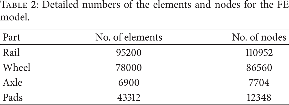
The model is meshed with 3D, 8-Node structural SOLID185 elements [27]. Mapped mesh is utilized in order to obtain a highly precise solution with a logical model size. Sections of both the rail and the wheel are mapped meshed and extruded as depicted in Figure 3. It is worth to note that this problem is solved with different sizes of elements, and the optimum solution is prescribed by trial and error to obtain the converged solution. As a result, tiny elements are used in contact areas. A total of 217565 nodes and 262689 elements (including structural and contact elements) have been considered. Table 2 represents detailed numbers of elements and nodes for the FE model.
Detailed numbers of the elements and nodes for the FE model.

Mapped meshed section and extruded model.
2.4. Interactions
Between the rail and wheel as well as between the rail and pads, a typical contact has been defined with 3D, 8-Node surface-to-surface Contact-174 and 3D Target-170 segment elements with standard behaviour. Also, the bonded contact between the axle and the wheel is characterized by 3D, 8-Node surface-to-surface Contact-174 and 3D Target-170 segment. These elements have adaptation capability with SOLID185 elements and can simulate the influence of friction between the rail and wheel [27]. Here, the friction coefficient of 0.2 is chosen for the FE analysis, [28].
2.5. Boundary Conditions
In this study, the geometrical boundary conditions are applied based on physical characters and real conditions of the railway system. Symmetry boundary conditions have been implemented to both ends of the rail. Y and Z directions of pads have been constrained because they are held by sleepers, and X direction of them is restricted as they are hindered by guide plates. On the other hand, displacements along the X and Y axes as well as rotation about the Y and Z axes of the axle are constrained on account of keeping the slope of the wheel on the rail.
Due to the rolling motion of the wheel, the axle has been given the rotation of 3 radians about its axis and a 1380 mm displacement along the rail direction which is in accordance with the approach of motion of the instantaneous center. Instead of applying vertical forces on any component, the wheel has been pushed into the rail to obtain reaction forces equal to the quasi-static loads based on [16]. Derailment coefficient has been considered in the range of safety limit, while vertical and lateral reaction forces were being calculated.
3. Results and Discussions
The analysis of Von-Mises stress in the rail and the wheel are performed and the plastic and elastic strains in Rail-Wheel contact areas as well as assessment of contact nodal normal forces are evaluated, and then, the diagram of vertical force versus solution time for the critical contact areas is carried out. In this context, the rotation of 3 radians and a 1380 millimeter displacement are applied to the center of the axle. Rotational displacement of the wheel on the rail, for 4 time instances, is exhibited in Figure 4. This displacement is given to the wheel because of two significant reasons. First, it can ensure that the route of the wheel includes two setting pads completely, which are important in assessing the nature of the contact forces fluctuated along the wheel's route. Second, this distance is required for the rolling contact to obtain the required quasi-static state.

Total displacement of the wheel on the rail in 4 time instances (a) t = 0.25, (b) t = 0.5, (c) t = 0.75, and (d) t = 1.
Figure 5 shows Von-Mises stress distribution in the system as the wheel rolls on the rail, in 5 time instances. Also, the perpendicular section to the axis of the wheel route and an isometric view of the rail in contact zone are presented. The maximum amount of the stress for the rail on the Rail-Wheel contact areas is 524 MPa as illustrated in Figure 5. The amount of the stress created by the wheel motion on the rail exceeds the yield stress of the rail (483 MPa). This is because of plastic deformations, so the corrugations of the surface take place. According to Figure 6, the maximum Von-Mises stress for the wheel is 453 MPa in the last time instance, even though we cannot ignore small amount of stresses created in both the rim and the plate of the wheel. Note that the shape of the contact zone is relatively elliptic which is adjusted with the Hertzian method for the stress distribution. Besides, it should be taken into account that the rail has plastic deformations, since a large part of the contact forces between the rail and wheel is tolerated by the rail.

Von-Mises stress distribution in the system for 5 time instances (a) t = 0.00625, (b) t = 0.25, (c) t = 0.50, (d) t = 0.75, and (e) t = 1.

Von-Mises stress distribution in the wheel for 5 time instances (a) t = 0.00625, (b) t = 0.25, (c) t = 0.50, (d) t = 0.75, and (e) t = 1.
In every cycle of the wheel motion, the Von-Mises elastic and plastic strains are created as shown in Figures 7 and 8, respectively. The elastic strains are available above the section of the rail, as well as in the body of it. Plastic strains are merely created above the section of the rail. Hence, accumulation of these plastic strains among the time will result in the alteration of the rail's profile and its corrugation. As presented in Figure 9, corrugation with wavelengths of 4–8 cm occurs due to the plastic strains along the rail which is a result of rolling contact on the rail. Contour of the plastic strains of the rail in Figure 8 is exactly matched with the real-life experience shown in Figure 9. It illustrates that profiles of the corrugated areas are similar to zones subjected to plastic strains.
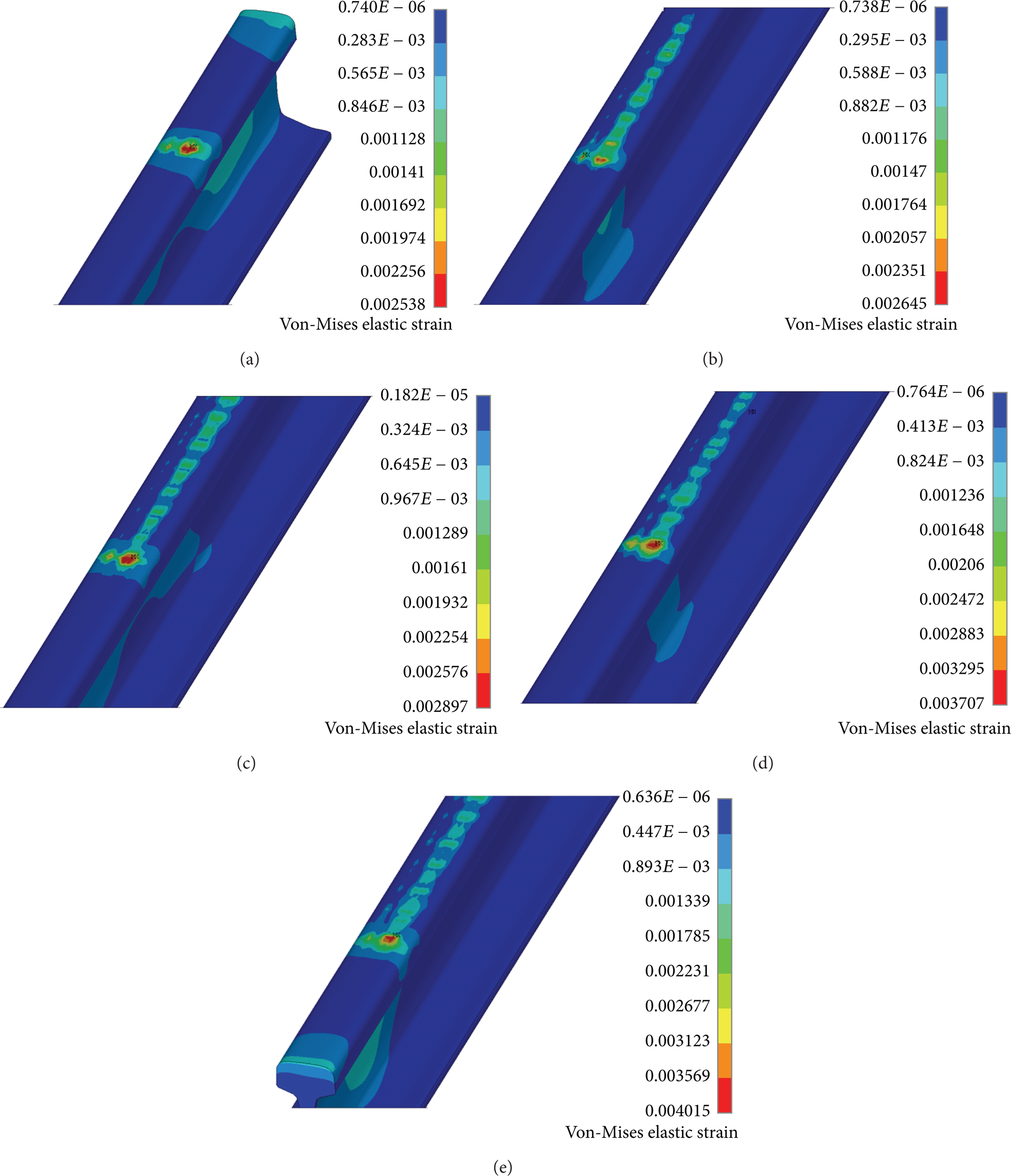
Von-Mises elastic strain distribution in the rail for 5 time instances (a) t = 0.00625, (b) t = 0.25, (c) t = 0.50, (d) t = 0.75, and (e) t = 1.

Von-Mises plastic strain distribution in the rail.

Real-life rail corrugation with wavelengths in the interval 4–8 cm occurs due to the accumulation of plastic strains [29].
Contact status, contact penetration, and contact pressure at the end step are also exhibited in Figure 10. The maximum amount of contact pressure is obviously placed in the center of the ellipse. Contact status demonstrates approximately elliptical shape of the sliding contact zone similar to contact penetration shape.

Contact status, penetration, and pressure distribution at the end step.
The final part of this section is devoted to nodal forces as a fundamental part of the interpretation of other findings in FEM software packages. During the rolling motion of the wheel, the existence of pads under the rail leads to the regular oscillation of vertical nodal forces in the rail and wheel. Diagram in Figure 11 elucidates the fluctuation of nodal forces in the axle center. To obtain these results, instead of setting the vertical load and utilizing the flexibility method, mutual interaction displacement between wheel and rail is set, and the displacement approach is used. As mentioned in Section 1, the axial loads in new railway systems have been augmented; thus, the vertical force applied by the wheel in the standard Rail-Wheel interaction is chosen 200–375 kN, since it can be more than 200 kN for problems with quasi-static characteristic [16, 26].

Variation of normal force versus solution time.
4. Conclusions
Finite element analysis (FEA) is utilized as a tool for contact mechanics modeling, assessment, and simulation of the Rail-Wheel contact through improving the traditional approaches of investigating the impact of the wheel motion on the rail. Most of the conventional methods and computational approaches are limited to static solutions without taking into consideration the complete rolling of the wheel. Furthermore, some simplifications of models of the railway system, that is, ignoring the setting pads in these studies, decreased the exactness of the solution. Followings are conclusions obtained by ANSYS software.
The displacement applied on the shaft in vertical direction is based on the magnitude of vertical forces which are validated by both experimental and numerical analyses of previous researches.
Results show that the Von-Mises stress on the rail is above its yield point and also the shape of stress distribution is elliptical. Either of these results is verified by several numerical studies.
Resulted by rolling contact forces, plastic strains can lead to abrasion, corrugation, wear, and crack propagation. As mentioned, plastic strain zones are the same as the plastic deformations in real-life Rail-Wheel interactions.
The present study can be as one of fundamental researches for rolling contact causing fatigue, wear, and abrasion, and therefore, improving and pursuing this study can be considered in future works. Directions of the future research are to investigate the influence of pads in nodal forces, stress distribution, and strains created by the wheel on the rail. It is worth to note that pads are also subjected to different types of lateral and vertical loads. Therefore, stresses and strains on pads are needed to be studied.