
Abstract
Structural health monitoring (SHM) can enhance the functionality of structures, improve its safety and reliability, reduce maintenance costs, and increase the service life. A new kind of SHM technology based on piezoelectric ceramic transducers is an effective way to realize the prospective functions. However, many of piezoelectric ceramic SHM systems, which are complicated, weighty, and having much equipment, are mainly used for laboratory researches. In order to meet the needs of engineering applications, a portable piezoelectric concrete SHM system which uses the virtual instrument technology is proposed and produced in this paper. The developed system which is based on piezoelectric transducers can be realized to monitor online vibration accelerations, dynamic stresses, concrete cracks, and so forth. The function of this integrated system has been effectively proved in test and in an engineering application. The experimental and applied results show that the system is reliable, of high degree of automation, and portable. The work provides important technical support for improvement of structure design and monitoring of structural health status.
1. Introduction
In the field of civil engineering, the security issue for concrete structures as one of the most widely used form of structure has always been concerned because of significant shortcomings of the concrete structure such as easily cracking. The appearance of cracks not only weakens the bearing capacity of the member, but also enables the reinforcement to expose in the air then makes the reliability of the structure greatly reduce. Therefore, the health monitoring technology of concrete structures has become one of the research focuses in recent years. The SHM is the use of on-site nondestructive sensing technology, through the analysis of the structure system characteristics including structural responses, to achieve the purpose of detection of structural damage or degradation [1]. Among them, the use of piezoelectric ceramic transducers for health monitoring of concrete structures has achieved initial results.
At present, the piezoelectric concrete structural health monitoring technology has two main categories: active monitoring technology and passive monitoring one. According to the damage diagnosis methods, the active monitoring technology is divided into the wave-based method and the mechanical impedance method. For the wave-based method, the basic principle is the use of inverse piezoelectric effect of piezoelectric ceramic which was used to produce transducers, which are arranged in the structure as a certain array, so as to establish the actuator-sensor channel to realize the component interval scanning, through the analysis of the difference of signal to achieve identification and diagnosis of structural damage [2–10]. In recent years, a new technology called smart aggregate that uses embedded piezoceramic has been used to monitor cracks in concrete structures [11–16]. Electro-mechanical impedence method by comparing the mechanical impedance value of the structure to judge whether it is damaged or not [17–21]. The passive monitoring method mainly measures dynamic responses of the structure which refers to the high-impedance characteristics of piezoelectric ceramics. At present, applications using the passive monitoring method are mainly concerned with structural vibration condition monitoring, impact load monitoring, and structural monitoring based on acoustic emission technique. In 2006, Yang from Tianjin University used this method to experimentally monitor the deformation of a two-story reinforced concrete frame structure under earthquake ground motion [22]. The test results showed that the piezoelectric ceramic can effectively monitor stress changes of the structure. In 2007, Song et al. carried out tests of an overloaded truck hitting the high-speed bridge, using piezoelectric ceramic sensors to monitor the impact load of the structure. The results showed that the piezoelectric ceramic transducer can correctly reflect the impact load value [23].
The technology achieves good results in the laboratory research stage however, due to the lack of development of the corresponding monitoring equipment system, its application in engineering field is greatly limited. The monitoring system for laboratory research use is often realized by the signal generator, power supply, charge amplifier, oscilloscope, and other independent instruments. Many of these systems are complicated and weighty, and data processing and further damage identification are mostly offline manual processing; it is inconvenient to be used in engineering applications. Sun et al. [24, 25] have built piezoelectric monitoring systems that rely on offline manual data processing. Massive data caused a huge amount of work, and many devices limit the system application environments. Therefore, the development of a set of portable piezoelectric health monitoring systems for the real-time and online monitoring of concrete structures is imperative. It is of great significance to promote the application of the technology in the practical engineering. Development of structural health monitoring system based on virtual instrument technology can make good use of the software on hardware for unified management and enhance real-time data acquisition and processing. The flexible graphical software interface is user-friendly. In recent years, the technology in the field of health monitoring has a certain development. In 2008, Qiu and Yuan used LabVIEW to develop an integrated health monitoring piezoelectric scanning system [26]. Myer Charles stadium in Milan developed a distributed health monitoring system with LabVIEW and CompactRIO platform by the Polytechnic University of Milan.
In this paper, a multifunctional integrated piezoelectric health monitoring system was developed to meet the need of engineering application. Relying on NI CompactRIO embedded platform as the core, it is convenient to the corresponding ancillary equipment and platform configurations to meet different functional requirements. Using the LabVIEW graphical software for integrated management of the hardware can make full use of hardware resources and provide the user with easy operation, flexible graphical user interface. The function of the proposed system is verified by both experiments in laboratory and the engineering application of wind turbines concrete foundation. The validation studies have shown that the integrated system, developed in this paper for high precision, good reliability, compact structure, and being scalable and highly available, can be effectively applied for the health monitoring of concrete structures. In the later, the user also can expand the system according to the increasing demand.
2. The Description of the System
Currently, a variety of piezoelectric sensor health monitoring systems often consist of the independent instruments, and software compatibility between each other is poor. Especially, for the use of piezoelectric monitoring technology to build the monitoring system, the hardware such as oscilloscope and signal generator is independent and of low degree of automation, and data processing also relies on artificial offline processing, resulting in a heavy workload, and this cannot meet the need of engineering applications.
The system is based on piezoelectric health monitoring technology, and the original monitoring system was optimally designed by using the virtual instrument technology. By adding a series of hardware or software, a reconfigurable test instrumentation system which is based on software and hardware supplemented with good interactive interface is formed. Based on NI CompactRIO embedded platform, users can achieve a variety of applications on a single system through modular configurations. By taking advantage of LabVIEW graphical programming software for unified management of various software modules, simple operation and easy extension, and function can be defined by the user.
The overall structural design of the system is divided into hardware configuration and software design [27]. The hardware configuration of the system mainly consists of the selection of sensors, data acquisition instrument, and other ancillary equipment. The logical relationship configuration diagram of the system is shown in Figure 1. The system's hardware core is the United States NI company's CompactRIO embedded platform (including NI 9263, NI 9221, and NI 9234). By configuring different sensor platforms and associated ancillary equipment to achieve different application functions on the CompactRIO embedded platform.

Logical relationship configuration diagram of the system.
The software design of the system is based on the LabVIEW graphical programming environment by choosing the United States NI LabVIEW 2010 development software, LabVIEW RT 2010 and LabVIEW FPGA 2010 toolkits, to develop the program code of modules. The main function modules have active monitoring module, passive monitoring module, and acceleration monitoring module. Among them, the active monitoring module mainly uses the active monitoring technique of piezoelectric ceramics for crack online monitoring of concrete structures, the passive monitoring module can be used in the dynamic impact load collection, and the acceleration monitoring module is applied to achieve structural vibration monitoring information collection.
3. System Hardware Realization
3.1. Sensor Configuration
Sensors of the system mainly include piezoelectric smart aggregates which can be sensors and actuators in the active monitoring module. Piezoelectric smart aggregates by calibration can be made into force sensors, which are used to collect pressure in the passive monitoring module. The acceleration module uses the built-in IC piezoelectric acceleration sensor of Lance.
The piezoelectric smart aggregate production principle, shown in Figure 2, mainly uses positive inverse piezoelectric effect of the piezoelectric ceramic. When the piezoelectric ceramic is forced, the mechanical energy will transfer to electrical energy, and the use of the piezoelectric effect can be made into sensors. On the contrary, under the action of an electric field, the piezoelectric ceramic can also convert the electric energy into mechanical one, which is the inverse piezoelectric effect and can be used to make actuators.

Piezoelectric effects.
Because of the frangible material of the piezoelectric ceramic such as lead zirconate titanate (PZT), it can be embedded into a small volume of concrete to make a smart aggregate encapsulated into a cylindrical shape after a certain processing method, shown in Figure 3, and a photo of the piezoelectric smart aggregate is shown in Figure 4. The developed piezoelectric smart aggregates can fasten to the given places before casting concrete to establish a monitoring array for the SHM use.

Illustration of a smart aggregate.

Two smart aggregates.
The piezoelectric force sensor is based on the piezoelectric smart aggregate, shown in Figure 5. The PZT force sensor works as a capacitor, and the vertical surface will produce charges when it is applied by a force. According to the longitudinal piezoelectric effect, the amount of charges generated by the piezoelectric ceramic sheets will be proportional to the force; then the relationship of the force and the charge can be established, shown in


Piezoelectric force sensor.
The piezoelectric acceleration sensor of LC0101 is selected, shown in Figure 6. Its main parameters include the sensitivity of 100 mV/g; the acceleration range of 50 g; frequency range of 0.5–15000 Hz (±10%).

LC0101 piezoelectric acceleration sensor.
3.2. Data Acquisition Devices
In order to meet the needs of SHM system, the NI CompactRIO 9074 embedded platform, the NI 9263 analog output card, and the NI 9221 and NI 9234 analog signal input cards are selected for the system.
The CompactRIO embedded platform, which integrates the embedded real-time controller, programmable hardware logic (FPGA), and reconfigured I/O module, was developed by American National Instrument Company (NI) for the test and measurements. The I/O module of the CompactRIO embedded platform can finish the input, output, and control for all kinds of digital/analog signals (such as voltage, current, and resistance), and the researcher can hot-swap, plug, and play to meet the different needs of engineering applications. The NI 9221 and NI 9263 modules are chosen as the active and passive monitoring modules for the system, and the NI 9234 is used for the acceleration acquisition module. Composition diagram of the data acquisition equipment and its main technical parameters are shown in Figure 7.

Architecture of CompactRIO embedded system.
3.3. Other Ancillary Equipment
The system according to the needs of different monitoring module is also equipped with a number of auxiliary equipments, mainly used for signal amplification, A/D conversion, and conditioning, which mainly include the driving power for piezoelectric ceramics, charge amplifier, signal conditioning, and UPS power.
The main function of the piezoelectric ceramic power is using it as the power amplifier of piezoelectric ceramic driver to generate signals in the active monitoring module, and the charge amplifier is mainly applied for the pressure acquisition in the passive monitoring module. Because the piezoelectric force sensor can receive the charge signal and the signal acquisition card is suitable for the voltage signal and the sensor output signal is very weak, the transformation of the signal amplification and charge voltage realized by a charge amplifier is required. Due to the built-in IC piezoelectric acceleration sensor works need motivation, so the signal conditioner should be configured. Considering the fact of no power in the actual monitoring field, the system is also equipped with a number of independent UPS power supplies.
4. System Software Design
The system modular design is applied for the software part of the system, and the main advantage is convenient for expanding the function of the system according to actual needs. According to the different functions of each module, the system is divided into the active monitoring module, the passive monitoring module, and the acceleration monitoring module. The active monitoring module can realize the signal transmission, acquisition, the crack damage identification, and sound and light warning. The passive monitoring module can complete the real-time acquisition of dynamic responses of the structure and a series of data processing. The acceleration acquisition module can accomplish the real-time acquisition and filtering of data and the spectrum analysis of the acceleration signal.
4.1. Active Monitoring Module
The active monitoring module mainly monitors cracks of the concrete structure, based on the wave-based method of the active monitoring technology. The basic principle is that piezoelectric smart aggregates, which are used as transducers, are embedded in the given places of the concrete structure. The actuator emits signal and the sensor receives signal, resulting in establishing an actuator-sensor scanning channel. Based on the analysis of changes in the signal and the extraction of the damage factor, the on-line system for monitoring crack damages of concrete structures can be realized. The hardware of the module mainly includes piezoelectric smart aggregates, piezoelectric ceramic drive power, the CompactRIO platform, the NI 9263, the NI 9221 card, and computer. The diagram is shown in Figure 8.

Physical structure diagram of the active monitoring module.
According to the results of research by our group [24], in the concrete structure, the amplitude of the signal analysis is sensitive to the crack damage, and with the injury increases, the more severe attenuation of the amplitude. So we selected the signal amplitude as the damage characteristic parameter, and through the further quantification of the characteristic parameter, referred to as the energy value. The energy value is the amplitude of the signal after discretization and the absolute value of the square integral. For

If

It is not difficult to see that, when the structure is in a healthy condition,

The software of the active monitoring module can realize the signal transmission and acquisition, signal processing and analysis, damage identification, warning, and data storage. The man-machine interface is shown in Figure 9. The workflow of the software is, first of all, for the module to provide the sweep wave and sine wave pulse signal according to the actual need. Then, the NI 9263 emits a signal and the NI 9221 receives the signal by the program control of CompactRIO embedded platform. Next, after the real-time acquisition original signal is filtered and denoised, the signal can be processed for the damage identification. The determination of the structural crack damage can be made based on the energy attenuation identification algorithm. The energy value obtained from the response time historical curve is used to characterize the structural health state from a macrostandpoint. Finally, the system will automatically compare the damage index with the corresponding threshold and achieve sound and light warning on the status of the structure.

The human-machine interface of active monitoring module.
4.2. Passive Monitoring Module
The passive monitoring module is developed based on the active monitoring module. When the passive monitoring of structures is needed, the system signal source is closed, and the piezoelectric smart aggregates are used as sensors to achieve the related physical quantity acquisition. Compared to the active monitoring module, the passive monitoring module in terms of equipment or software is relatively and greatly simplified. Due to having no excitation source, the passive monitoring module is mainly composed of sensors and the data acquisition system.
In practical engineering, data acquisition systems often collect voltage signals. In general, the charge signals from sensors need to be transformed into voltage signals. To establish the correspondence between voltage and pressure, the data acquisition system often needs to be equipped with a charge amplifier.
The passive monitoring module in the system can realize the synchronous acquisition and online processing of four channel data. The software interface is shown in Figure 10.
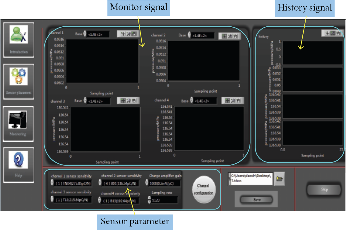
The human-machine interface of passive monitoring module.
4.3. Acceleration Monitoring Module
The acceleration monitoring module utilizes piezoelectric acceleration sensors to measure the dynamic acceleration response signal of the structures during an earthquake or wind loads [28, 29]. The system mainly includes acceleration sensors, signal conditioning, data acquisition platform (CompactRIO embedded platform and NI 9234 module), and PC control module. The workflow is that, first of all, the sensors need to be arranged in the structure according to the measurement requirement. The sensors can put into normal work by conditioning supply power, and the sensor signal is transformed into a voltage signal, transmitting into the data acquisition module. The PC control module controls the data acquisition platform for collection and processing as well as analysis of data.
The module interface is shown in Figure 11. The developed software can realize four channel data, acquisition, filtering, spectrum analysis, data storage, and other functions. It can monitor the peak of signals to achieve sound and light warning when the acceleration exceeds the given threshold.

The human-machine interface of acceleration monitoring module.
5. Test Validation and Application of the System
Because the development of the system is a process, according to different needs, the several modules are developed individually. In the later use of software integration for each module of the system, the testing and engineering application of each module introduced below will be separated.
5.1. Experimental Verification of the Active Monitoring Module
In the whole function test of the module, a reinforced concrete beam element as the monitoring object is selected, shown in Figure 12(a). The size of the model is

The active monitoring module test.
The test adopts a gradual loading plan, and the states of the tested concrete structure are divided into the health state (no cracks), slight damage (initial crack), moderate damage (cracks significantly increased), and severe damage (structural failure). Each damage state is shown in Figure 13.

The different damage states of the components.
The developed system is used in the experiment for real-time online monitoring. The signal transmission and data acquisition are performed for every time interval of 10 s. To eliminate noise interference caused by external factors such as local data instability, the test for each state continuously scans 100 times. The damage index of each state is shown in Figure 14. The state of the damage index is at a different level, showing that the structure damage is in different states. The damage index is growing with the increase of the degree of damage. Meanwhile, the warning module can achieve a sound and light warning for different damage states. The results show that the system can efficiently monitor and identify the process of concrete crack damage and it achieves the design goal.
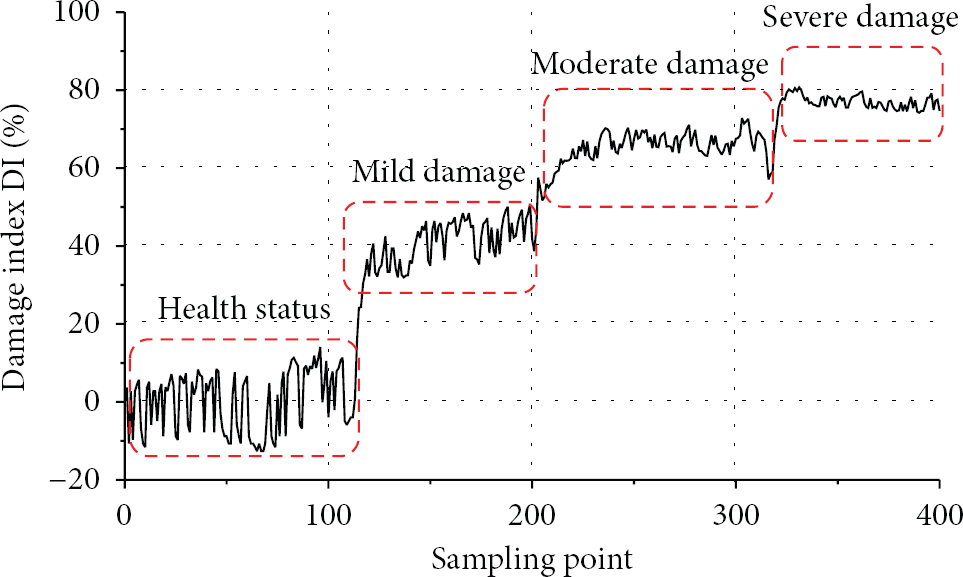
Monitoring data in four different conditions.
5.2. Engineering Application of the Passive Monitoring Module
A new kind of steel bolt RC foundations for rock soil is used for the wind drive generators constructed in 2012 in Guodian Tieling wind farms which are located at the Development Zone of Tieling city, China. In order to study the interaction of new rock bolts and concrete foundation which influences the force performance of wind turbine foundation, the passive monitoring module is developed on the basis of established system, through which you can understand the real-time status of the internal stress distribution, and the work also can put forward the reasonable proposals for design and construction.
In view of the load of wind turbine foundation composed by the static and dynamic loads, the project will use the piezoelectric sensors to obtain the dynamic stress inside the foundation, through a combination of theoretical calculations that show the actual internal stress of foundation. The structural health monitoring system is established by placing the developed smart aggregates in the foundation. The sensors are distributed at the horizontal direction along the circumferential uniform layout, divided into inside and outside layers, and relatively closely placed at the main wind direction, and the vertical direction is divided into two layers. Each sensor is numbered, and B, T, BN, and TN denote the bottom, the upper, the bottom inner ring, and the upper inner ring, respectively. The layout of sensors in site of the project is shown in Figure 15.

Layout of sensors in field.
Sensors were arranged in the wind turbine foundation before pouring the concrete. In May 9, 2012, the first field testing of the wind turbine foundation is completed, and fans condition is shutdown. In order to facilitate inspection and checking of the results, the stress of different locations on-site monitoring was extracted from sensors, to compare with the numerical simulation results.
The comparison between calculated and monitored values is shown in Figure 16 [30]. The monitoring results show that the stress of different positions inside the wind turbine foundation has the consistent change with numerical simulation. However, due to the difference of the actual load with respect to the numerical calculation, there are some differences between the two values. For this project, under the action of moment generated in the wind loading, the leeward side of wind turbine foundation is mostly in the state of compression and the windward side of ring outside and the anchor position are in tension. It can be concluded that the system is running well and work in a stable way.

Measured stress and calculation analysis of stress.
5.3. The Experimental Validation for Acceleration Monitoring Module
In order to test the reliability of the acceleration monitoring module, a three-layer steel frame model is used in the paper as an experimental monitoring object. The model height is 500 mm, and the slab thickness is 5 mm. The beams and columns adopt the round steel tube whose outer diameter is 8 mm, and the inner diameter is 4 mm. The overall size of the model is 500 mm × 400 mm × 400 mm, and the 10 kg mass is placed on each floor.
In order to simulate the real acceleration response of the structure under earthquake, a shaking table test is chosen and performed in Structural Engineering Laboratory of Shenyang Jianzhu University, China. The Shake Table II — 240 produced by Canada QUANSER company is used. Four acceleration sensors are placed at each layer; the sampling frequency of 5.12 kS/s is selected. At the same time, the traditional acquisition equipment is chosen to synchronously collect the same parts of the acceleration signal, which is used for the comparison of test data and verification of the accuracy of the data. Field test equipment of the system is shown in Figure 17.

Field test equipment.
The Northridge wave record whose maximum acceleration is 0.1 g is used as excitation seismic waves of vibrating table during the test selects. The acceleration signal of the first layer of the frame structure is selected as an example for analysis. In Figure 18(a), the time-history curve of the original acceleration signal of the frame structure at the first layer collected by the system is shown. Due to the interference of noises in the testing site, the collected signals by the sensor cannot completely represent the structure vibration characteristics. Therefore, the original signals need to be performed for noise filtering. By analyzing the frequency spectrum of the signal, the acceleration signal spectrum curve of the structure at the first layer can be obtained, shown in Figure 18(b), showing that the fundamental frequency of the structure is 2.2 Hz. Therefore, this system chooses the Butterworth band-pass filter, and the filtered signal frequency is greater than 5 Hz and less than 1 Hz. Finally, the acceleration signal at the first layer after filtering is shown in Figure 18(c). In Figure 18(d) the acceleration signal at the first layer after filtering is shown, which is synchronously collected by dynamic signal analyzer TST5912. From the comparative analysis between Figures 18(c) and 18(d), it can be seen that the time-history curve of vibration signal collected by this system is nearly the same as the acceleration time-history curve collected by traditional instruments, the maximum acceleration of both is 0.74 m/s2. Therefore, we can conclude that this system can effectively collect structure vibration signal and its data is accurate and reliable.

Comparison and analysis of acceleration signal at the first floor.
6. Conclusions
The advantage of virtual instrument technology is taken in the paper to develop a concrete structural health monitoring system which is based on piezoelectric sensors. Through the test and engineering application, it shows that the system can not only realize the damage identification and sound-light alarm but also can achieve the online monitoring of acceleration, stress state, and other physical quantities. Using the graphical programming software LabVIEW to develop the structural health monitoring system, it has a good human-computer interaction interface and short development time. It is suitable for nonprofessional engineer to complete project development. At the same time, CompactRIO embedded platform with a compact and rugged feature, which is very suitable for complex and bad environments of construction site. It achieves the leap from stationary health monitoring system to the portable the health monitoring system. The work provides a good technical support to solve practical problems and has a good foundation for piezoelectric health monitoring technology from the laboratory research to the engineering application.
Footnotes
Acknowledgments
This work was financially supported in part by the National Natural Science Foundation of China (51278313), the Natural Science Foundation of Liaoning Province (201202180), the Science Foundation of Liaoning Education Department (L2012214), Key Laboratory Foundation of Liaoning Province (JG2009-18), and Liaoning Electric Power Survey & Design Institute Foundation.