
Abstract
Energy harvesting from ambient resource such as solar power improves the sustainability and continuous monitoring capability of sensor nodes. However, energy conservation and harvesting can hardly provide a complete solution due to two main reasons: the energy harvesting capabilities/opportunities are seriously affected by spatial and temporal facts regarding the location of sensor deployment, and distributed processing of sensing and communication are also uneven throughout the network which leads to unbalanced energy consumption. In this paper, we propose an energy transfer system called eLighthouse to level the energy harvesting and consumption of solar-powered WSN. An energy-hub equipment has been brought forward utilizing a controlled retroreflector to forward sunlight to the appropriate nodes which urgently require recharging. The scheduling algorithm among multiple nodes is also included in this paper which helps to maintain the maximum number of nodes in active state; the localization algorithm which enables the controlled retroreflector for pointing correctly is also a key contribution of this paper. The experimental and simulation results both demonstrated that the proposed system can maximize the utilization of the solar power charging technique effectively to prolong the network lifetime and build up a sustainable WSN.
1. Introduction
Limited energy supply has been the main constraint of battery-powered system such as wireless sensor networks which provide continuous monitoring in ambient environment. It greatly affects the sustainability of WSNs and has disproportionate impact on the fidelity. In this area, the recent research topics are mainly focused on two categories: energy saving and energy harvesting.
A natural mechanism of energy saving is enhancing network protocols, such as energy-efficient MAC protocols, routing protocols, and data aggregation as shown in [1–3]. The goals of these researches are not only to reduce the energy consumption rate but also to balance it. However, these schemes can only prolong the network lifetime to a limited extend but fail to make it sustainable. A promising solution to this problem is to explore energy harvesting and acquiring techniques. Solar power, wind power, and vibration power have all been introduced as perspective energy resource of tiny sensor nodes. Corresponding hardware design and experiments have also been introduced in many papers although it still suffers some limitations such as costliness, inflexibility, and low efficiency. Furthermore, without sufficient energy acquiring approaches, these methods cannot work well.
On one hand, as a network performing distributed monitoring tasks, data communication and collection process are seriously dependent on task requirement and network topology. Sink nodes and other nodes near hot spots or in a busy route tend to consume their energy more rapidly which means energy consumption among the network that is unevenly distributed. On the other hand, the energy harvesting capability at each node may vary significantly due to environmental geometric. For example, the amount of harvested solar power in a sensor node varies due to factors of weather, location, and time, in spite of Maximum Power Point Tracking function being used. In one word, the energy harvesting is unbalanced as well as energy consumption. Researches have been carried out to balance the energy distribution, such as [4, 5]. However, these approaches only consider the energy usage pattern corresponding to the energy harvesting rate, in which the faster recharged nodes carry more operation responses. It is not always feasible to level data communication by the energy harvesting capability. A heavy loaded sensor node may be deployed at energy-poor locations and become the bottleneck of the entire network.
To balance energy between nodes, energy share system could be a solution. Energy can be transferred to other nodes via wires, microwave, magnetic resonance, laser, and so on. Wired transfer does not fit for wireless sensor networks and Magnetic resonance has very low efficiency. Microwave and Laser require additional high-cost equipments which have huge overhead under current technology. Despite the poor performance of current energy sharing system, the idea of energy transfer between sensor nodes still has its potential in energy balancing. The key design goal is to improve the energy transfer efficiency. In our opinion, transferring the initial state of the harvested energy may be a promising way. Therefore, in this paper, we propose a sunlight reflection based resource energy transfer method for solar energy harvesting sensor networks. During daytime, it does not produce special means of energy such as electrical, laser, magnetic resonance, microwave, and so on but only relay the ambient energy in the initial state. Sunlight is reflected by a retroreflector for recharging capability enhancement to specified nodes in an inappropriate place, for example, nodes in shaded area or with heavy loads. To improve efficiency, spare energy accumulated during daytime can also be transferred to nodes by wireless energy transfer means in the night or during bad weather.
The proposed system consists of (1) a sunlight reflection and solar power harvesting station called energy hub (2) wireless sensor nodes equipped with solar panel and light sensor. The energy hub can adjust the onboard retroreflector and reflect sunlight to enhance the recharging capability of specified nodes and charge them like a lighthouse. Fundamental experiments have been carried out to prove the feasibility of the proposed mechanism as well as evaluation of the energy transfer efficiency. A prototype system has been produced and the corresponding scheduling algorithm has also been introduced to ensure the network lifetime extension, which aims to build up a sustainable sensor network system. However, we meet some design and implementation challenges, such as accurate localization of the solar board with a maximum tolerable error of centimeter level, precise sunlight reflection positioning, and real-time energy recharging scheduling.
This method fits well for infrastructured environment as it requires line-of-sight (between the energy hub and the sensor node with solar panel). As shown in Figure 1, each node may have different opportunities to receive sunlight (denoted by percentage) due to the movement of the sun. By applying the proposed method, it can efficiently provide reflected sunlight or wireless energy against the shadow. For large networks in a more complex environment, our method can also improve energy efficiency by deploying energy hubs locally and carefully.

Energy harvesting ability varies from node to node.
More specifically, the main contributions of this paper are concluded as follows.
We designed and implemented a solar power transfer system for energy harvesting sensor networks, which is a novel means of efficient initial state energy transfer scheme. We proposed a sunlight reflection strategy which can reflect sunlight to the solar panel of the nodes in need. The strategy includes solar panel covering and retroreflector adjusting. We have proposed an accurate node locating algorithm for sensor node localization, which combines camera and RSSI locating method. We have developed a charging scheduling algorithm which guarantees the sustainability of sensor nodes. We conducted model simulations and also built a proof-of-concept prototype of the system and conducted extensive experiments on the prototype to evaluate its feasibility and performance. The results indicate that our system can efficiently enhance sunlight coverage and improve network performance.
The remainder of the paper is organized as follows. In Section 1, the motivation is introduced, while, in Section 2, related works are described and evaluated. The system model and design are discussed in Section 3, and the node locating mechanism is presented in Section 4. Section 5 discusses the scheduling of the charging sequence, followed by simulation and experimental evaluations in Section 6. Finally, Section 7 concludes the paper.
2. Related Work
To prolong lifetime of sensor networks, energy harvesting has been proved to be a promising key. Solar power, wind power, vibration, and even human power [6] can all be the energy source. Design, modeling, and capacity planning for energy harvesting sensor network are evaluated in [7]. However, the energy harvesting opportunity of each node is far from each other and varies with respect to temporal and spatial facts.
Energy share methods are introduced to solve this bottleneck problem, which implies energy transfer between nodes or from energy station to nodes by means of wired or wireless electrical power exchange technologies. Magnetic resonance, developed by Kurs et al. [8], has become a major technique for wireless energy transfer, based on which some recharging scheduling algorithms have been developed, [9, 10]. Other studies utilizing wired energy transfer are conducted as well. Zhu [11] developed an energy charging and discharging mechanism using an array of ultracapacitors as the main component of an energy router through wired connections, which is known as eShare. However, according to [10], wireless charging efficiency is seriously affected by distance. Charging efficiency is approximately 1.5% when the energy receiver is 10 cm away from the charger. The charging efficiency decreases to zero when the distance approaches 100 cm. The controlled electrical energy transfer between wired ultracapacitors is also not as regular as mentioned in [11] due to physical characteristics of the component, which has some nonlinear features. Another main disadvantage is the low efficiency caused by the wasted energy in transfer circuit. Above all, electrical energy share schemes are still in a design or laboratory experiment level at the recent stage.
Localization has been a hot topic for years. However, the accuracy depends on node density and available facilities. Most of the range-based methods can be concluded into four categories, which are time of arrival (TOA), time difference of arrival (TDOA) [12], angle of arrival (AOA) [13] and received signal strength indicator (RSSI) [14]. Range-free methods are mentioned in [15–17].
References [18, 19], which use Corner Cube Retroreflector (CCR) to transfer man-made laser and mirrors to transfer lamplight by optical means, are the most similar work compared with our approach. In [20], the authors propose using external energy transmitters (ETs) to charging sensor nodes by wireless means. ETs are assumed that they have endless power and can be deployed randomly or predetermined. The paper does not discuss the placement of ETs but proves the feasibility of this energy station-based method and the routing and data transmission issues under the circumstance. References [9, 21–23] both focus on mobile energy station which can prolong network lifetime by traveling among nodes and charging them wirelessly. The main concern is the movement and trajectory of mobile energy station (also be called ferry, charging vehicle, mobile charger, etc.). Watfa et al. [24] try to extend current one-hop wireless energy transfer to a multihop manner. They investigate both theoretically and through simulations whether the physical phenomenon of long-lifetime resonant electromagnetic states with localized slowly evanescent field patterns can be used to transfer energy efficiently over multiple hops. In [25], the placement of RF power transmitters is bounded with missions of sensor nodes. RF power transmitters will be moved to Landmarks among sensor networks according to current missions and maximize the energy usage and the profit. The key problem is how to choose Landmarks and the authors propose ILP to solve it.
3. System Description
3.1. System Overview
As can be seen from Figure 2, in eLighthouse system, there are sensor nodes and energy hubs. Each energy hub can cover certain amount of sensor nodes. The coverage area can be either identical or variant. The energy to power a single sensor node comes from energy harvesting from solar power. Sensor nodes might run out their batteries so that part of communication connections between nodes becomes intermittent shown as dashed lines in the figure. There are two major problems. First, because of the movement of the sun and shadow of the environment, each node does not have an equal opportunity to receive sun radiation. The principle of eLighthouse system is based on sunlight reflection by the retroreflector. By adjusting the angle of the retroreflector, the energy hub can redirect the sunlight to those nodes sheltered from trees or other obstacles. The energy hub itself is equipped with a powerful solar panel so that its energy supplement is not the key point of this paper. That is to say, even during the night, energy hubs can provide energy with means of wireless energy transfer. Second, because the sunlight and wireless energy transfer can only generate feeble electric current, we need to find ways to speed and easily store the energy. Regarding the first problem, we need to solve further two more problems. One is how we can find the node and compute the corresponding angle of retroreflector. The other is who and how long we should forward the sunlight to. eLighthouse is suitable for plain area deployment where trees and bush are not too flourishing. The energy hub is often deployed in a relatively open area or higher location and with large energy harvesting equipment so that its own energy consumption needs no considerations. Regarding the second problem, we use super capacitors as the energy storage.

Sensor network architecture with energy hubs.
3.2. Hardware Implementation
The architecture of eLighthouse sensor network is shown as in Figure 3, which is composed of two parts, energy harvesting sensor nodes and the equipment called energy hub. The sensor nodes are composed of (i) the sensor board equipped with multiple sensors in which light sensor is a fundamental part while other sensors are optional, (ii) a square
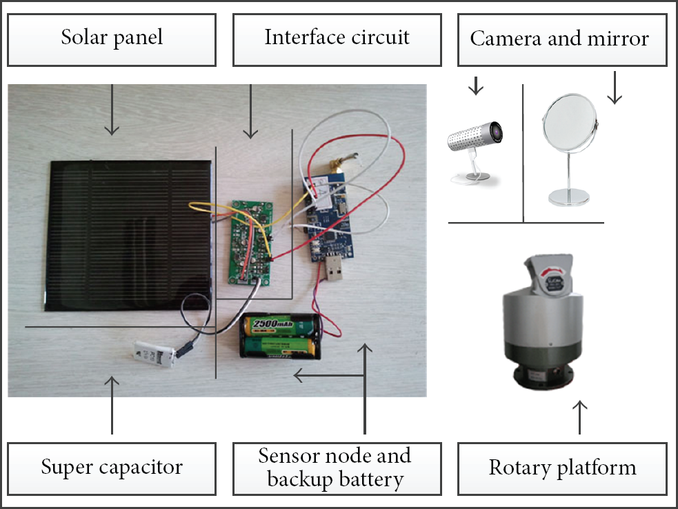
Hardware components of eLighthouse.
Li-ion or other batteries normally cannot support fast charge and respond slowly to weak charging current. Therefore, using a single Li-ion battery is not enough to satisfy future development of wireless sensor networks. Also the residual energy of Li-ion battery is hard to compute accurately and it does not have a linear relation between residual energy and voltage. Furthermore, for a long-time deployment, charging cycle is essential to the sensor battery. To maximize the usage of energy and schedule sensor nodes efficiently, as well as routing protocol, the residual and charging energy of battery should be accurately calculated. Regarding super capacitor, its residual energy is in accordance with the formula
The energy hub consists of (i) a rotary platform that can pan and bend so as to adjust angle of the retroreflector, (ii) a retroreflector which is used to reflect sunlight, and (iii) a camera for accurate localization of node as an assistant of RSSI method. The energy hub is connected to a TelsoB node which will receive residual energy information from other nodes and perform scheduling algorithm to control the rotary platform. in most occasions, the energy hub itself is equipped with a set of powerful energy harvesting devices, for example, with larger area of solar panel. The energy harvested during daylight can be used to charge nodes during the night. However, energy has to be transmitted using wireless means when there is no sunlight. Without losing generality, if we regard energy hubs as all-weather energy suppliers, problems that include how to cover sensor nodes with minimum energy hubs and how to schedule charging sequence will be addressed in Section 5.
3.3. Software Implementation
The software components are built on TinyOS 2.1 and run on each sensor node in the network. Besides normal data collection, the sensor node is running status report task periodically. It also keeps measuring its residual energy status and will require the energy hub to transfer sunlight when the energy is below certain thresholds. The control and scheduling software component is running on the TelosB node attached with the energy hub. It communicates with other nodes through 802.15.4 interface.
Normally, one energy hub provides sunlight transfer to several nodes. We need to identify the following things. First, who shall be responsible for initializing the energy transferring process? Second, how to control sunlight reflection between a pair of sensor node and energy hub? Third, how to balance the collision of multiple energy transferring requirements?
To begin an energy transferring process, there could be two kinds of methods. Namely, energy hub initialized and sensor node initialized schemes. In [11], the node whose energy is going to be below critical level will cast an energy sharing request to nodes listed in descending order of efficiency. However, in a network scale view, energy should be reserved as much as possible. In our design, energy is stored in the super capacitor. Therefore, higher energy reservation will lead to higher energy leakage. Hence, energy pairing is related to two things, energy level and using pattern. When a node's battery is going to be flat, it will be an initializer as in [11]. Also, when in daytime, an energy hub will become an initializer.
If an energy hub and node go into sunlight reflection procedure, the initializer sends out a REFLECTION_REQUEST message. After receiving the message, the other one may answer with message REFLECTION_RESPOND. When a sunlight reflection process starts, the energy hub will generate a REFLECTION_START packet and try to locate the node. The node will direct the locating process with its light sensor. When the desired amount of sun radiation has been transferred, the energy hub sends out the REFLECTION_STOP packet. However, the node can also send out REFLECTION_STOP packet to terminate the sunlight reflection process under certain circumstances.
The software flowchart of sensor nodes is shown in Figure 4. After initiation, sensor nodes always measure their battery level and report to energy hubs. If energy level is below certain threshold, for example,

Software flowchart of sensor nodes.
The software flowchart of energy hubs is shown in Figure 5. They monitor battery status of appurtenant sensor nodes, analyze their energy consumption and harvesting model, and then perform charging sequence scheduling to enable sensor nodes stay working as long as possible. Besides initiating charging in scheduling they need also to respond to immediate energy transfer request.

Software flowchart of energy hub.
4. Energy-Aware Node Locating
4.1. Accurate Node Localization
In our proposed scheme, in order to reflect the sunlight accurately to the solar panel of each sensor node, an important step is the localization of all the solar boards. There have been many methods introduced for localization, which are either range-based or range-free [15]. Since range-free approaches use hop count and the average distance as the measurement standard, they are not able to be applied in our scenario which only considers one-hop distance situation.
In our scenario, as the localization precision is relatively high which requires the reflected light directly positioning the solar board, all the above schemes cannot satisfy the requirement. However, the localization in our scenario is not a global network localization; it only covers approximately one-hop distance, or even shorter. A benefit raised from this situation is that we can use video camera on the platform to coordinate the accurate positioning. Light sensor embedded in the sensor node also can help to increase the accuracy by communication feedback. The detailed system procedure, the localization process, and the corresponding geometrical model are shown as follows.
We assume all the sensor nodes are deployed in a plane area, and the height of the retroreflector in the energy hub is known as H. The sink node is connected to the energy hub and located exactly below the retroreflector which is set to be the original point of the coordinate systems. In the sensor node deployment and network initialization stage, the positions of the manually deployed sensor nodes are set to be known parameters. By converting the rectangular coordinate system
During the long-term monitoring of the sensor network, newly added nodes may change the topology and the connections of the network. Correspondingly, the localization information requires updating. In our method, fundamental RSSI is used as a first step for rough localization. The newly added nodes that will broadcast a short beacon message in a particular transmit power strength, which is power level 10 in CC2420 for our experiment. Those neighborhood nodes that receive this information will use the received signal strength to calculate the distance from the radio source and report it to the sink. The correspondence between distance and the signal strength has been measured in advance. This sink node will select two-distance information from the location-known nodes and that collected by itself to determine the

Example of node locating.
However, our experiment results show that the error of this RSSI measurement and location calculation is up to a level of 1-2 meters with an approximately 20-meter

Camera assisted node locating.
4.2. Single-Node Solar Panel Coverage
It is also a challenge to enable reflected light to fully cover the designated solar panel so that the utility of solar power can be maximized. After accurate node localization, the right angle of retroreflector should be calculated and the hardware component has to be correctly positioned by the rotation of the rotary platform. Then, the minor adjustment will take place to make full coverage according to the response of the sensor node.
Assume that the location of a node has been acquired using our locating algorithm so that we know the distance and height and is able to compute its relative location to the energy hub. The detailed process is described as follows. In Figure 8,


Solar power reflection.
After obtaining γ and α we can control the rotary platform to reach the position.
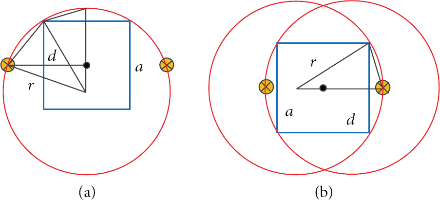
With the knowledge of the accurate node location, it does not guarantee that the entire surface of the solar panel can be covered by the reflected sunlight. The solar panel may be located to any side of the sensor node, which generates a design challenge of the proposed scheme. In this paper, we use slow moving capturing combined with feedback from the nodes to solve this problem. When the light is reflected to the node, it will result in increasing of luminous flux of light sensor. However, the location related to the solar power has a great impact on performance of the method. We summarize four situations as shown in Figure 9. In Figure 9(a), the light sensor is covered by all the circles while none of the circles provides full coverage of the solar panel. In Figure 9(b), the light sensor is covered by none of the circles while each circle provides full coverage of the solar panel. In Figure 9(c), it is desired situation that the solar panel and the light sensor are both covered. Let us analyze the situation using multiple light sensors. All possible placements of light sensors around the solar panel are shown in Figure 9(d). When two light sensors are deployed separately on the two sides of the solar panel as two yellow dots, in most occasions, we can clarify that the panel is fully covered upon both light sensors being covered. The choices of location are proved as follows.

On single node solar pad coverage.
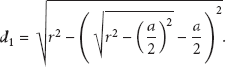
The placement of light sensors is decided by the size of the solar panel and the light coverage circle. For simplicity, let r stand for the radius of the light circle, let a denote the side length of the solar panel, and let d be the distance between the light sensor and the center of the light panel. Figure 10(a) shows the specified case that two sensor nodes are within maximum distance between each other. The distance d can be calculated as follows:
Computing of light sensor placement.
The best placement of light sensor is shown in Figure 10(b), and it can be computed as follows:

As a result, the distance of the light sensor should not be greater than
5. Scheduling of the Charging Sequence
We consider a wireless sensor network ℕ consisting of N sensor nodes that are randomly distributed in a two-dimensional area of size
A number of M energy hubs ℍ are deployed in the same area to charge the sensor nodes, where each energy hub
We assume that all energy hubs have unlimited energy capacity, a similar charging power of
To keep continuous energy replenishment, each sensor node
The problem that we intend to solve is to find the minimum number of energy hubs, together with their deployment locations and charging sequences of their covered sensor nodes, such that all nodes stay alive.
5.1. System Model
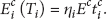
We consider a system consisting of N sensors nodes. Each node
The energy consumption rate of node

The sensor nodes are recharged periodically by the energy hub. Denote
Let
5.2. Problem Description
We first examine some conditions that must be satisfied before the problem is formally defined.
Lemma 1.
A node

Proof.
We prove the following by contradiction. Assume the node goes dead during the mth period at time


Assume that

Lemma 2.
A node
Proof.
We prove the following by contradiction. If

From Lemma 2 and (5), we deduce that

However, it is not sufficient to claim that a node stays alive if the recharging time satisfies (13). This is because if recharging happens when the energy level of node
Lemma 3.
A node

Proof.
The node is guaranteed to be recharged with energy of amount
We then prove the following by contradiction. Assume the energy level exceeds


Lemma 4.
A node

Proof.
Regarding (10), if
Equation (17) means that during each period

We now formally define the schedulability problem mentioned at the end of Section 5.1.
Definition 5.
The system described in Section 5.1, subjected to the following constraints:


5.3. Schedulability Analysis
To guarantee that each node
Definition 6.
The system described in Definition 5 stays alive if and only if N tasks, each of which has period
Using the well-established scheduling theory of real-time systems [26], we have the following.
Lemma 7.
The system described in Definition 5 stays alive if

Equation (23) shows that smaller recharging time
5.4. Selection of
From (20) and (21), we know that
Also notice that keeping
5.5. Selection of the Period
In this section, we discuss the selection of the period
On the other hand, from (17), (20), and (21), we have


Meanwhile, certain energy-harvesting methods, for example, solar power, pose a limitation on the available charging time. Furthermore, when the characteristics of the power source or node workload (and accordingly the power consumption) change, the schedule must adapt to the variation. It would then not be suitable to choose a too long period in such circumstance.
In a word, period
5.6. Energy Hub Coverage
As described in [28], the problem of covering all sensor nodes using a number of charger nodes is not similar to the widely studied coverage problem in Wireless Sensor Networks. The latter one can be mainly of two types: area coverage and target/point coverage, which intend to find the required number and exact locations of sensor nodes that cover an entire piece of area or a limited number of targets. While our problem, on the other hand, is to find a minimum number of energy hubs and their corresponding locations such that all sensor nodes in the network will receive continuous energy replenishment.
We adopt the framework proposed in [28], which utilized grid approximation, minimum set cover problem, and greedy approach. The difference lies in the fact that we do not neglect the charging time and consider real-time charging scheme, while in, [28], the charging time is assumed negligible and an energy hub is able to charge all sensor nodes within a certain range. Thereby, in our algorithm, sensor nodes that will be covered by an energy hub must satisfy that (1) they are within the energy hub's effective charging range R and (2) they do not violate (23).
To convert the infinite search space to finite one, the grid approximation technique is applied, where the deployment area of sensor nodes with size
Energy hubs are located one by one. At each step, the best location of an energy hub is obtained by testing in the finite search space. Upon finding the best location for the energy hub, its covered sensor nodes are removed. The next energy hub is to be found in the same manner but considering only sensor nodes that have not yet been covered by any energy hub. The procedure continues until all sensor nodes are covered. The pseudocode is shown in Pseudocode 1.
It is shown that at each step of the while loop, a function
Each step of finding the location of the next energy hub
order (
Notice that, in the pseudocode shown in Pseudocode 2 at each grid point
6. Evaluation and Experiments
We both use simulation and testbed to evaluate our proposed methods.
6.1. eHub Coverage
This section will demonstrate the effectiveness and performance of the proposed algorithm. In addition, the method presented in [28] will also be tested and compared with our algorithm. In particular, we denote the two methods as follows.
Greedy-R-based refers to the method proposed in [28] where, at each step of locating the next charger, the greedy search selects the grid point where maximum number of sensor nodes will be covered based on the criterion that they are within the charging range R. Greedy-U-based is the method presented in this paper and differs from the above method in the criterion of determining which sensor nodes will be covered, where the condition of (23) must be also considered.
In the first simulation, we randomly deploy 12 sensor nodes in an area with dimension of
For each energy hub to be deployed, it has charging power

The simulation is performed in Matlab, and its results of finding deployment of energy hubs using Greedy-R-based method and Greedy-U-based method, respectively, are shown in Figure 11. In the figures, dashed lines mark the grid, small solid squares denote sensor nodes, and each circle denotes an energy hub's charging range, while an energy hub is located at the center of a circle that coincides with a grid point. The location of each energy hub is labeled as

Deployment of energy hubs using Greedy-R-based and Greedy-U-based methods.
It is shown in Figure 11(a) that, using Greedy-R-based method, the first energy hub
The difference of the results produced by two methods is due to the fact that, when charging time is non-negligible, an energy hub is only capable of charging a limited number of its neighboring sensor nodes. To clarify our point, we have performed another simulation of charging the 4 sensor nodes covered by energy hub
Figure 12 shows the energy level of node

Energy level of node
Furthermore, even when a real-time scheduling algorithm is applied for the charging sequence scheduling, it is still not able to guarantee that all sensor nodes stay alive. In Figure 13, we show the energy level of node

Energy level of node
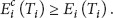
In contrast, the deployment of energy hubs obtained by our proposed method (Greedy-U-based) guarantees the required charging time of each sensor node and manages to keep the energy level of all sensor nodes above
Energy levels of the 3 sensor nodes covered by energy hub
To evaluate the performance of the proposed algorithm, the third simulation is performed. In this simulation, 80 sensor nodes are randomly deployed in a

Comparison of the number of deployed energy hubs w.r.t. the step size of grid approximation.
Figure 15 shows that a smaller step size of grid approximation leads to a smaller number of required energy hubs, for both methods. On the other hand, the number of deployed energy hubs acquired by Greedy-U-based method is larger than that by Greedy-R-based method. This is true because Greedy-U-based method considers not only the charging range R but also the schedulability of an energy hub's covered sensor nodes and hence requires more energy hubs to cover all sensor nodes. Notice that the gap between two methods is not significant with respect to the number of sensor nodes and decreases as step size enlarges.
6.2. Charging Scheduling
Two simulations have been conducted to verify the effectiveness of the scheduling policy described in Section 5.
In the first simulation, we consider a system with 3 sensor nodes, each powered by a super capacitor with the maximum voltage level
Table 1 listed the setting is of the above parameters, as well as the resulting
Parameters of sensor nodes.

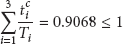
Using EDF as the scheduling algorithm, we have
Let

Recharging three sensor nodes using EDF scheduling algorithm.
6.3. Evaluation on Real Platform
We also build a proof-of-concept system to evaluate proposed model. The experiments are established on real solar-powered sensor network. Our experiment can be categorized into two parts. First, we conduct tests on how different ranges of reflection affect the sensor node with solar power harvesting component. This is to evaluate the possibility of transfer energy by reflecting sunlight and its efficiency. Furthermore, we obtain charging pattern when distance and luminous intensity vary in different scenario. Second, we use a flashlight as simulated sun light and form a real network to examine node locating algorithm and performance of scheduling.
As seen in Figure 17, we sets up three set of sun light reflection systems which are 50 cm, 100 cm, and 200 cm, respectively. The experiments are conducted using plane mirrors and concave mirrors, respectively. From Figure 18 we can know that using concave will get better efficiency. It will only take 3 minutes to charge the super capacitor while plane mirrors need about 10 minutes to achieve the same goal. No matter what kind of methods are used, the charging efficiency is better than that of magnetic resonance. As expected, the distance between energy hub and receiver will affect the efficiency. Energy experience loss due to scattering while range increases. However, it is hard to tell the difference between three distances when concave mirrors are employed.

Experiment of three different reflection distance.

Charging facts with different mirror type and distance.
We also evaluated our model in an environmental deployment as shown in Figure 19. Node 2 is directly facing the sun and others are in the shadow of trees. Each node will report its status periodically. If their energy drops to a certain degree, they will ask for energy transfer. Then, the energy hub will turn to transfer energy simulated as in the light of the flashlight. If more than one node is in shadow, the energy hub will turn to the one which has higher priority computed using scheduling algorithm. If a new node is added, the energy hub will locate it by RSSI. After that a test reflection will be conducted to measure the exact location. Then, the coordination of the new node will be recorded by the energy hub.

Outdoor deployment of the eLighthouse system.
To evaluate node allocating and functionality of scheduling algorithm we performed indoor experiments as shown in Figure 20. We set up an energy hub with eight stationary nodes and use flashlight to simulate reflected sunlight. Each node will report its status periodically. When a node is shaded it will ask for energy transfer. We use boxes to shade one node at a time. The energy hub will turn to and direct the flashlight to the node to simulate the energy transferring procedure. If multiple nodes are in shadow, the energy hub will turn to the one which has higher priority computed using scheduling algorithm. We also did experiment of adding a new node. When a new node is deployed, the energy hub will locate it by RSSI and camera. After that, a test reflection will be conducted to measure the exact location. The charging efficiency of flashlight is shown in Figure 21. The experiments show that the proposed model is feasible.

Indoor testbed using flashlight.

Charging facts of flashlight.
7. Conclusion
This paper has presented an energy share system to coordinate the energy harvesting wireless sensor network to achieve energy balance and lifetime prolonging. It has clarified that, by using solar power reflection system, efficient initial state energy transfer can be achieved with inexpensive energy hub equipment. A simple but effective scheme for short distance sensor node accurate localization has been introduced and demonstrated as well as the sunlight retroreflector positioning method. The practical experiments prove the correctness of the design criteria and provide an outstanding performance. An introduction of the energy-aware scheduling mechanism has been carried out along with the derivation of the accuracy, which enables the network to be energy balanced and sustainable. Through the proposed approach and corresponding algorithm, a novel way of achieving lifetime maintenance and energy balance in Wireless Sensor Networks has been pointed out with high potential.
eLighthouse system has its own limitation during night or unfavorable weather. In the future, we plan to extend the work by considering cooperative charge, in the sense that a sensor node can be charged by more than one energy hub. In fact, we have assumed in this paper that energy hubs have unlimited energy. Although this is a reasonable assumption when energy hubs are located in environment where the energy for harvesting is abundant, this may not hold in certain practical scenarios. In that case, assigning a set of sensor nodes to only one energy hub for charging is not sufficient, and a multiple coverage scheme is required to handle this issue.
Footnotes
Acknowledgments
This work is supported by the National Natural Science Foundation of China (Grant no. 60903167, 61202093, and 61272539), the Zhejiang Province Natural Science Foundation (Grant no. Y1110831), the subfoundation of Zhejiang Provincial Key Innovation Team on Sensor Networks under Grant no. 2009R50046-4, and the Scientific Research Foundation for the Returned Overseas Chinese Scholars, State Education Ministry.