
Abstract
Structural health monitoring of the cable-anchorage system is very important to secure the integrity of the cable-stayed bridge. The cable-anchorage system carries most of the self-weight, so that any damage in the system may significantly reduce the load carrying capacity of the bridge. This study presents a multiscale structural health monitoring of the cable-anchorage system using piezoelectric PZT sensors. Firstly, the electromechanical impedance response is utilized for alerting the change in anchorage zone caused by the loss of cable force or local anchorage damage. Secondly, the dynamic strain of cable is utilized for classifying the damage type. Thirdly, the loss of cable force and the anchorage damage are quantified by a frequency-based cable force model and an impedance-based damage estimation model, respectively. The feasibility of the approach is evaluated from the experiment on a lab-scale cable-anchorage model for which several damage scenarios are simulated about cable damage and anchorage damage.
1. Introduction
Cable-supported structures such as cable-stayed bridges have been widely constructed around the world. Bridges can be larger and even slimmer thanks to prestressing techniques. Also, the risk gets worse as the failure of prestressing system could result in significant reduction of load carrying capacity and even collapse of the bridge. Damage in cable-anchorage system can be classified as cable force loss and anchorage damage. The cable force loss is caused by creep and shrinkage in concrete, relaxation of cable stress, and corrosion of tendon. The anchorage damage is mostly caused by corrosion or cracks. Therefore, the integrity of the cable and the anchorage zone is an important issue to study for the healthy status of the cable-supported structure.
The demand on structural health monitoring (SHM) has been increased in aerospace and civil infrastructures over the past two decades [1, 2]. Among a variety of SHM studies on cable-anchorage system, many researches have focused on monitoring of cable force by using vibration response of cable or impedance response of anchorage [3–6]. The vibration-based method can give accurate estimation of cable force. However, vibration feature is not sensitive to damage in anchorage zone. On the other hand, the impedance-based method has been found sensitive to any structural change in local area like anchorage zone. By utilizing electro-mechanical impedance of anchorage zone, the loss of cable force or anchorage damage would be detected.
In this study, a multi-scale structural health monitoring of the cable-anchorage system using piezoelectric PZT sensors is presented. Firstly, the electro-mechanical impedance response is utilized for alerting the change in anchorage zone caused by the loss of cable force or local anchorage damage. Secondly, the dynamic strain of cable is utilized for classifying the damage type. Thirdly, the loss of cable force and the anchorage damage are quantified by a frequency-based cable force model and an impedance-based damage estimation model, respectively. The feasibility of the approach is evaluated from the experiment on a lab-scale cable-anchorage model for which several damage scenarios are made about cable damage and anchorage damage.
2. Multi-Scale SHM Method for Cable-Anchorage System
2.1. Design of Multi-Scale SHM
Hybrid SHM methods have been proposed by many researchers in order to examine multiple types of damage or to increase the accuracy of damage detection results. For example, Kim et al. [7] proposed a hybrid algorithm to detect different damage types in plate-girder bridges by utilizing acceleration and impedance features. Park et al. [8] has attempted to detect whether girder damage or prestress-loss occurs in prestressed concrete girders. Sim et al. [9] accommodated both acceleration and strain measurements to improve the capability of damage detection for truss structures. Also, Nguyen et al. [10] utilized both dynamic strain and impedance measured from PZT sensors to enhance the capability of damage localization for beam-type structures.
On the basis of the previous studies, a hybrid SHM method is proposed for detecting the multiple damage types in cable-anchorage systems such as anchorage damage and cable force-loss. The method utilizes the active and passive responses of piezoelectric sensors at anchorage zone and cable body, respectively. The hybrid SHM scheme is performed in 3 major steps. In step 1, the occurrence of damage is alerted by monitoring electro-mechanical (E/M) impedance of the anchorage zone. In step 2, the alerted damage is classified into cable damage or anchorage damage by monitoring PZT dynamic strain of the cable. Finally, in step 3, damage estimation is performed for the classified damage type. If cable damage is specified, the amount of cable force change is estimated. If anchorage damage is specified, the severity of damage is evaluated.
2.2. Damage Occurrence Alert
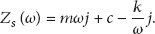
Both the loss of cable force and anchorage damage causes the change in structural characteristics of the anchorage zone. Then, inversely, the electro-mechanical impedance signature of anchorage zone can be utilized to detect the occurrence of those damage types. The impedance response is based on the coupling of mechanical and electrical characteristics [11]. In this method, a piezoelectric (PZT) patch is usually surface-bonded to a host structure. The electrical signals of the PZT are partly controlled by mechanical effect of the host structure. By actuating the PZT with a voltage and measuring the current, the impedance can be obtained as a combined function of mechanical impedance of the host structure,

Equations (1) and (2) show that any change in dynamic characteristic of the host structure can be represented by the change in E/M impedance. In this study, the change in E/M impedance is quantified by root mean square deviation (RMSD) index as


2.3. Damage-Type Classification
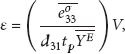
Once the damage is alerted, it should be classified as cable damage or anchorage damage using PZT dynamic strain response of cable. The fundamental of PZT dynamic strain has been studied by Sirohi and Chopra [12]. It is based on the direct effect of piezoelectric materials that an electrical field is produced due to mechanical strain of a PZT patch. When a PZT is bonded to the cable, strain response of cable can be expressed in term of the differential voltage measured between the PZT's terminals as

If the change in cable's natural frequency is observed, the damage in cable is alerted. Otherwise, the damage is specified to anchorage zone. Due to experimental and environmental errors, the upper control limit

2.4. Damage Severity Estimation
2.4.1. Frequency-Based Cable Force Estimation
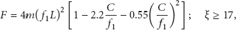
Once cable damage is alerted, tension force of the cable is estimated and the amount of cable force loss is calculated. In this study, the method proposed by Zui et al. [4] which considers effects of both flexural rigidity and cable-sag is used for estimating cable force by the following practical formulas.
Case 1.
Cable with small sag
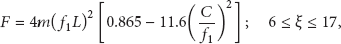

Case 2.
Cable with large sag


Case 3.
Very long cable:

2.4.2. Anchorage Damage Estimation
The impedance-based monitoring technique may not quantitatively estimate the change in structural properties via the change in impedance signatures [14]. Many researchers have reported that the change in impedance signature is generally increased with damage growth [15, 16]. In this study, anchorage damage is specified into ignorable, small, or moderate damage based on the RMSD level as shown in Figure 2. Two threshold values, Threshold 1 and Threshold 2, are, respectively, set as 1% and 2% for indicating small damage and moderate damage.
3. Experimental Verification
3.1. Description of Test Structure
As shown in Figure 3, an experiment was carried out for a lab-scale cable-anchorage model. The cable was comprised of 7 stainless steel ropes. The experimental setup is also described in Figure 4. The length of the cable was 6.4 m. The cable was anchored by two bearing plates at two ends. Detailed specifications of the cable are given in Table 1. For measurement of the cable's strain, a PZT sensor of 1 cm in diameter (PZT A) was bonded on a smart skin which tightly covers the cable at location 1.5 m from one cable end. The smart skin was designed to overcome the problem of bonding condition between the PZT sensors and cable surfaces. The deformation of the smart skin is secured by static friction in the interface between the skin and the cable. The skin plate should be flexible and should have low mass in order not to affect the response of the cable. Also, its thickness should be small enough compared to the cable section and its surface should have large frictional coefficient in order to guarantee the accuracy of strain measurement. The data acquisition system for PZT dynamic strain consisted of a NI-6036E DAQ card, a BNC-2090 terminal block and a PC with MATLAB. The NI-6036E DAQ card has the input impedance of up to 100 GΩ and the input data rates of up to 200 K samples/s which can ensure the proper sampling of the PZT sensor. The strain signals were recorded for 50 seconds with a sampling frequency of 500 Hz. For measurement of anchorage impedance, another PZT sensor of 1.5 cm in diameter (PZT B) was bonded on to one bearing plate. The E/M impedance signatures were measured by a commercial HIOKI 3532 impedance analyzer. The signatures between 450 kHz and 465 kHz were recorded with 801 interval points. During the test, room temperature was kept as close as constant of 23-24°C by air conditioners.
Specifications of cable.

3.2. Damage Monitoring Case 1: Cable Damage
Cable tension force was introduced into the cable by a hydraulic jack as the cable was anchored at one end and pulled out at the other. A load cell was installed at one cable anchorage to measure the actual cable force. Each test was conducted after the desired cable force has been applied and the cable has been anchored. During the measurement, the hydraulic jack was removed from the cable-anchorage system to avoid the influence of the jack weight on dynamic characteristics of the cable. The cable was first pretensioned to
The multi-scale damage detection is carried out in three steps as previously schematized in Figure 1. In the first step, the occurrence of damage is alerted using RMSD of impedance as described in (3). For each of the four tension force levels, impedance signatures were measured up to 4 ensembles from PZT B (on bearing plate as shown in Figure 4). As shown in Figure 5, impedance signatures were obtained for four cable force levels. By setting the impedance signature for the maximum tension force level,

Schematic of multi-scale SHM for cable-anchorage system.

Damage severity assessment for anchorage damage.
Schematic of cable-anchorage system.

Experimental setup.

Impedance signatures for 4 cable force levels.

Damage occurrence alert for cable force-loss.
In the next step, the alerted damage is classified by identifying the change in natural frequency of cable. For each of the four tension force levels, PZT dynamic strain responses of the cable were measured up to 4 ensembles from PZT A (on cable body as shown in Figure 4). Figure 7 shows a sample signal of PZT dynamic strain of cable. Figure 8 shows the change in power spectral densities of cable's strain for the four cable force levels. It can be seen that the power spectral densities shift left when the cable force decreases. The change in natural frequency is utilized to decide the damage type of the alerted damage. As shown in Figure 9, the changes in the first and second frequencies are larger than the control limit of about 1.6% and 1.25%, respectively. These results indicate that the alerted damage is cable-force loss, according to the multi-scale logics described in Figure 1.

PZT dynamic strain of cable for case

PSD of cable strain for 4-cable force levels.

Change in natural frequency for cable damage.
As the damage type is classified as the loss of cable force, the amount of cable force-loss is estimated from (8a)–(10). The cable force and the amount of loss are calculated as listed in Table 2. Both the estimated cable force and the loss show good match with the inflicted ones.
Cable force-loss monitoring results.
3.3. Damage Monitoring Case 2: Anchorage Damage
As shown in Figure 10, a crack was introduced into the bearing plate by saw cut for simulating the damage in anchorage zone. The crack was simulated with two levels corresponding to the ratio of crack depth to the bearing plate's thickness:
Simulated crack on bearing plate.
The multi-scale damage detection is carried out again in three steps as previously schematized in Figure 1. In the first step, the occurrence of damage is alerted using RMSD of impedance as described in (3). For each of the four tension force levels, impedance signatures were measured up to 4 ensembles from PZT B (on bearing plate as shown in Figure 3). As shown in Figure 11, impedance signatures were obtained for reference case and the two crack levels. The RMSD values between the reference and the two crack levels are calculated as shown in Figure 12. It is observed that the RMSD values increase with the growth of crack. For the two anchorage damage cases, the occurrence of damage is successfully alerted by the change in RMSD values.
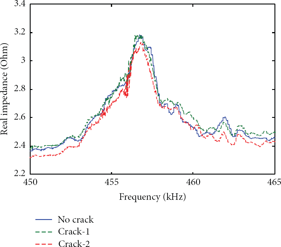
Impedance signatures for anchorage damage.

Damage alarming for anchorage damage.
In the next step, the alerted damage is classified by identifying the change in natural frequency of cable. For each of the reference case and two crack levels, PZT dynamic strain responses of the cable were measured up to 4 ensembles from PZT A. Figure 13 shows the power spectral densities of cable's strain for the reference case and the two crack cases. It can be seen that the power spectral densities do not shift when the crack increases. As shown in Figure 14, the changes in the first and second natural frequencies are smaller than the control limit. These results indicate that the alerted damage belong to anchorage damage, according to the multi-scale logics previously described in Figure 1.

PSD of cable strain for anchorage damage.
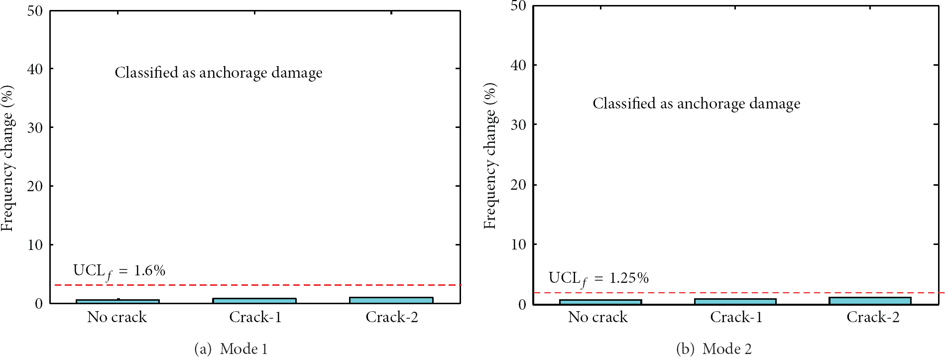
Change in natural frequency for anchorage damage.
As the damage type is classified as the anchorage damage, the severity of damage is examined by using the thresholds of impedance RMSD as previously described in Figure 2. The changes in impedance signatures for the two damage cases are quantified by RMSD index as listed in Table 3. According to the damage assessment logics for anchorage zone (Figure 2), the damage case Crack-1 is estimated as small damage since the corresponding RMSD index (1.42%) is larger than 1%. Meanwhile, the damage case Crack-2 is recognized as moderate damage since the corresponding RMSD index (2.27%) is larger than 2%.
Anchorage damage monitoring results.

4. Conclusions
In this study, a multi-scale structural health monitoring of the cable-anchorage system using piezoelectric PZT sensors was presented. In this approach, the PZT impedance response of anchorage was utilized for alerting the change in anchorage zone caused by cable tension force-loss or anchorage damage. Meanwhile, the PZT dynamic strain of cable was utilized for classifying the damage type. The amount of cable tension force-loss was estimated by a frequency-based cable force model, and the anchorage damage was evaluated by setting RMSD thresholds of impedance signatures.
The feasibility of the proposed system was evaluated on a lab-scale cable-anchorage model with several damage scenarios of cable damage and anchorage damage. The occurrence of either cable damage or anchorage damage was successfully alerted by monitoring electro-mechanical impedance of the bearing plate. Then the damage type was successfully classified into cable damage or anchorage damage. For the cable damage cases, the loss of cable tension force was accurately estimated. For the anchorage damage cases, the damage severity was specified into small or moderate damage, and the damage growth was successfully indicated by the increase of RMSD.
The future works are remained to examine the combination of cable damage and anchorage damage for multi-scale SHM. Also, temperature-compensated models should be studied to improve the accuracy of damage detection results.
Footnotes
Acknowledgment
This research was supported by a grant from a Strategic Research Project (Development of Smart Prestressing and Monitoring Technologies for Prestressed Concrete Bridges) funded by the Korea Institute of Construction Technology.