
Abstract
Wear and deformation CNC grinding machine tool, will be aggravated over time ofwhich will influence the manufacturing precision. To reduce the effect, the soft compensation method by modifying NC instruction was put forward to maintain the manufacturing precision of CNC crankshaft grinding machine tool. The error sources were analyzed, the errors caused by grinding force were calculated, and the precise grinding kinematics model was deduced by the multibody kinematics. Numerical simulation and manufacturing experiment were carried out and the rank tests were taken for the manufactured crankshafts. Experiments show that the manufacturer precision of the crank can be enhanced by 63.69%, 52.06%, 42.27%, and 30.96% by soft compensation of 10 years of service life and 10 μm grinding depth, 4 years of service life and 10 μm grinding depth, 10 years ofservice life and 6 μm grinding depth, and 4 years of service life and 6 μm grinding depth, respectively. Soft compensation can be applied to the machine tool in which the manufacturer precision has declined and the NC instruction with compensation should be updated periodically.
1. Introduction
Reliability of machine tool can be represented by two parameters of the fault probability of machine tool signed by f(t) and the defective rate of manufactured parts signed by r(t) [1]. f(t) and r(t) will be increased over time meanwhile. f(t) is affected by the ageing and degradation of the components and parts, and r(t) is affected by the wear and deformation ignoring the human and environment factors. Replacing and maintenance are good manners when f(t) is high, which is inoperative when r(t) is high. To lengthen the using life of machine tool and reduce the production cost, the soft error compensation for machine tool was proposed to maintain the machining precision and using reliability in this paper. Error model and compensation were deduced from CNC crankshaft grinding machine tool and the validity of error compensation was analyzed by statistical method.
Crankshaft is used in automobile and generator widely to transform the linear movement to rotational movement. The crankshaft machining precision will affect the power performance and stabilization of the engine. So, it has important significance of researching on the machining precision of crankshaft for improving the comprehensive performance for engine.
The study focus on errors settling of CNC machine tool is error measuring and identifying, kinematics and dynamics of noncircular grinding, and the compensation method. Zhu et al. proposed one method of measuring the geometrical errors by laser interferometer and Jywe and Liu proposed one geometric error measurement method of CNC machine tool using the improved planar encoder system [2, 3]. Möhring et al. proposed one active error compensation method in contour-controlled grinding [4].
Lechniat et al. and Cui et al. proposed the method of offline soft compensation for geometrical errors for CNC machine tool in reference [5, 6]. Slamani et al. proposed one error identifying method of five axes CNC machine tool [7]. Rahou et al. proposed the real-time compensation method for machine tool [8]. Bosetti and Bruschi proposed one method to enhance the position accuracy by direct measurement of deformation [9]. Raksiri and Parnichkun proposed one error compensation model for CNC milling machine taking into account geometrical and cutting force in reference [10].
The compensation for combinational errors of geometry and deformation by grinding force has not been studied for CNC crankshaft grinding machine tool. On account of this status, the precise grinding kinematics including geometrical errors and grinding force deformation errors was modeled by multibody system kinematics and the errors were compensated and simulated for CNC crankshaft grinding machine tool in this paper. The experiment was carried out to verify the analysis, calculation and simulation.
2. Errors Calculation
Errors of CNC crankshaft grinding machine tool are geometrical errors, grinding force errors, thermal deformation errors, servo tracking errors, and so forth. Geometrical errors can be measured and identified, grinding force errors can be calculated, and the other errors are difficult to quantize. So, the geometrical errors and grinding force errors are mainly objected to analysis and compensation in this paper.
2.1. Geometrical Errors Calculation
2.1.1. Geometrical Errors
CNC crankshaft grinding machine tool is one special triaxial machine tool which includes two linear axes signed as X and Z and one rotational axis signed as C. The action of axis X and axis C is linkage when working. Each working part of CNC crankshaft grinding machine tool has three linear errors as shown in Figure 1(a) and three rotational errors as shown in Figure 1(b) [11].

Geometrical errors of CNC crankshaft grinding machine tool: (a) linear errors and (b) rotational errors.
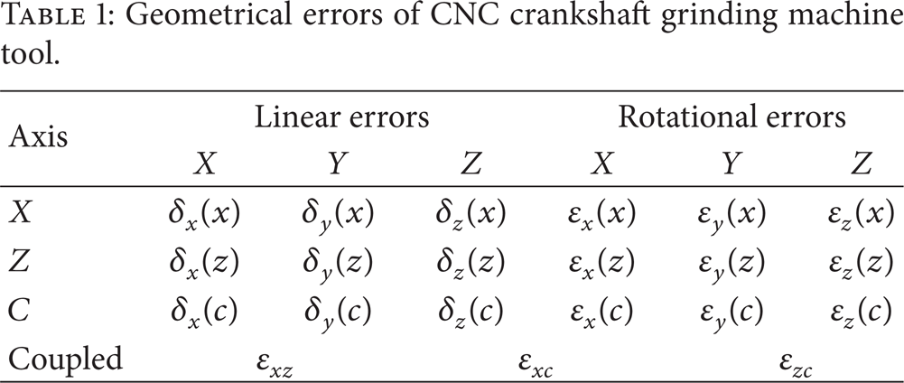
In addition, there are two vertical errors between axis X and Z and one coaxial error between axis C and Z. So the total number of geometrical errors of CNC crankshaft grinding machine tool is 21 as shown in Table 1.
Geometrical errors of CNC crankshaft grinding machine tool.
2.1.2. Multibody System
CNC crankshaft grinding machine tool has some moving and rotational parts and each part has 21 errors. The calculation of the composite errors is very complex and one calculation method by multibody system is introduced.
Multibody system is the most overall abstracting and summarization and is the most suitable kinematics and dynamics model for mechanical system, especially for complicate mechanical system in modeling and analysis [12]. The precise grinding equation model with geometrical error was created by multibody system as follows.
Mechanical system is composed of many parts commonly and the parts have spatial position relation and kinematical relation. Each moveable part is considered as one body and numbered by sequence of its movement link as shown in Figure 2. So, each point's coordinate of high body (the bigger of body number in two adjacent bodies) in low body (the smaller of body number in two adjacent bodies) coordinate system can be calculated by the product of point's vector in high body and the adjacent body matrix on conditional that the position relation and kinematical relation between the high body coordinate system and low body coordinate system are known.

Multibody system diagram.
The coordinate of any point of any body in inertia coordinate system can be calculated by the production of the multiplication of the adjacent body matrixes and the vector of any point of its body considering the whole movement link.
In Figure 2, body I and body J are one couple adjacent bodies, body I is the low body, and body J is the high body. The referenced coordinate system of body I and body J is O
I
and O
J
, respectively.


[
If α, β, and γ are very small, [
The coordinate of vector r K of body K in inertia coordinate system can be solved by (4):


If the position errors and movement errors exist, the adjacent body matrix is as

where [
2.1.3. Errors Calculation
The construction sketch of CNC crankshaft grinding machine tool is as shown in Figure 3, and it includes six bodies as base (B1), headstock (B2), crankshaft (B3), axis Z feeder (B4), axis X feeder (B5), and grinding wheel (B6).
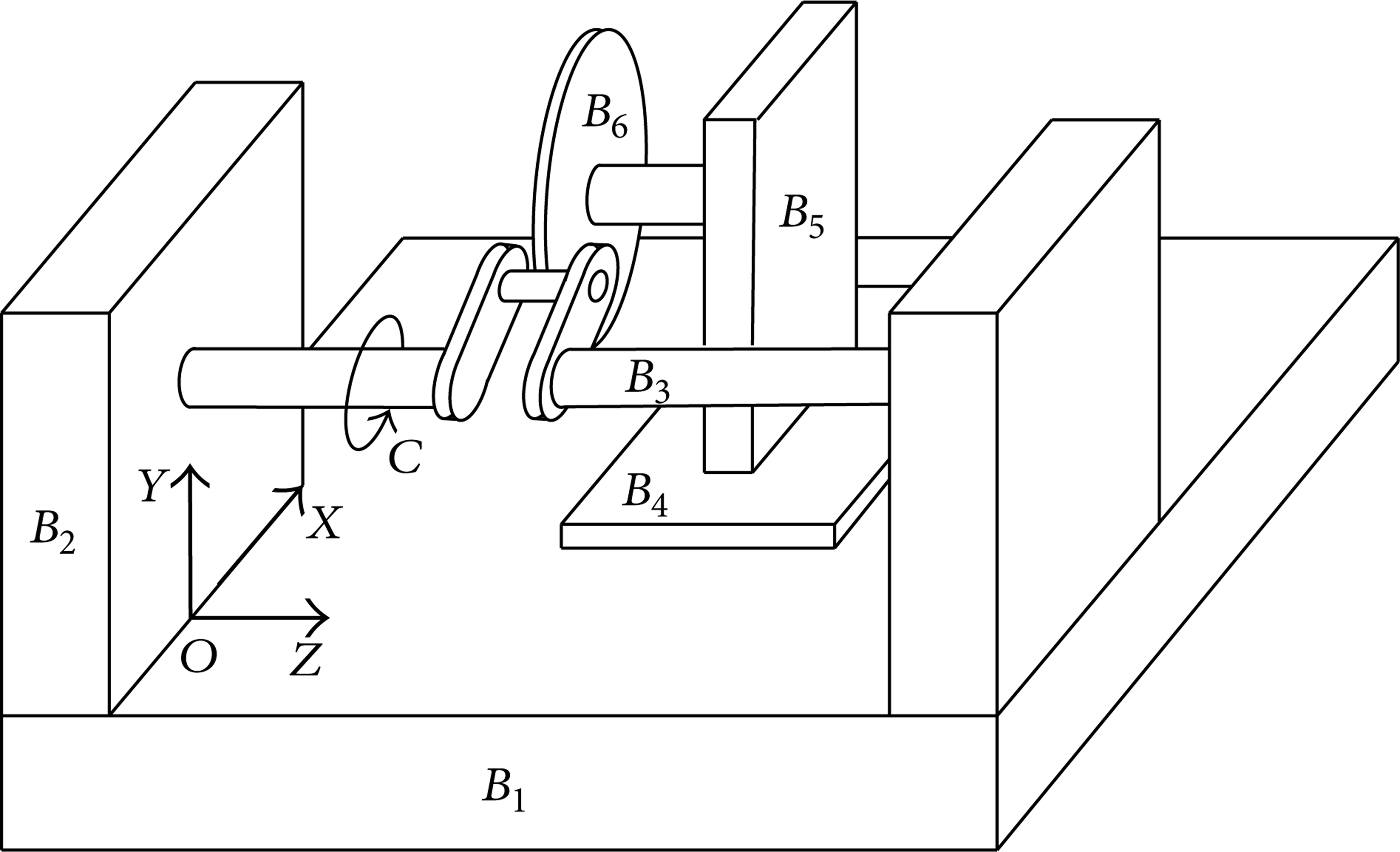
Structure of CNC crankshaft grinding machine tool.
The original point of inertia coordinate is located at the intersection between the end plane of B2 and the axial line of B3 by the feature of CNC crankshaft grinding machine tool, as shown in Figure 3. The coordinate of B2 is coinciding with the inertia coordinate, the coordinate of B3 offsets h3 along axis Y by the coordinate of B2, the coordinate of B4 offsets l4 along axis X by the inertia coordinate, the coordinate of B5 is coinciding with B4, and the coordinate of B6, whose original point is located at the center of wheel, offsets h5 along axis Y by the coordinate of B5. Each adjacent body matrix can be calculated by (19) after being a set of coordinates.
Two movement links are formed by six bodies of CNC crankshaft grinding machine tool. The multibody system topological graph containing position errors and movement errors between adjacent bodies of CNC crankshaft grinding machine tool is shown in Figure 4 by multibody system theory.

Multibody system topology of CNC crankshaft grinding machine tool.

Kinematics equation solving.
The coordinate of grinding point in coordinate of B3 and B6 can be gained by (6) and (7), respectively:


l OP can be calculated by cosine theorem in ΔO c PO g by

α can be calculated by sine theorem in ΔOPO g by

So the precise kinematics equation can be deduced as shown in (13), which is one linkage equation of axis X and C:

The relation of x and θ can be gained by (13) and the crank pin can be grinded as required the condition that x and θ meet (13) in NC instruction.
Equation (13) is suitable for every quadrant of grinding point because the sine and cosine theorem has no limit to triangle.
To compensate the position errors and movement errors, the coordinates of grinding point in crankshaft coordinate system and in wheel coordinate system should be known and it can be calculated as follows:

(x W , y W , z W ) is the coordinate of grinding point in crankshaft coordinate system:
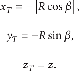
(x T , y T , z T ) is the coordinate of grinding point in grinding wheel coordinate system.
So, the expressions of vectors

2.2. Grinding Force Errors Calculation
There are three forces at grinding point of normal force signed as F n , tangential force signed as F t and axial force signed as F a when grinding as shown in Figure 6. F a is far less than F n and F t , and the error caused by it can be ignored, which is not analyzed and compensated. F n and F t can be equivalent to one resultant signed as F e and one moment signed as M e .

Crank pin forces analysis.
To eliminate the positioning and assembling errors, crankshaft is manufactured as one whole workpiece usually. Crankshaft can be seen as one slender rod and will produce complicated elastic winding and twisting deformation under the grinding force, which will influence the manufacturing precision of crank pin.
2.2.1. Influence of Grinding Force
When the grinding point is located at the first quadrant, the center of crankshaft will offset Δx and Δy to the third quadrant affected by F e and rotate Δθ anticlockwise affected by M e . considering four quadrants, the contour curve of crank pin will be one ellipse as shown in Figure 7. Curve A is the ideal contour, curve C is the actual contour, and curve B is the compensated contour of crank pin. M is the ideal position and N is the compensated position of the grinding wheel.

Crank pin deformation under the grinding forces.
The deformation is not invariant when different crank pin is grinded along the axial line of crankshaft, so that the compensation value is one function of z and θ.
2.2.2. Errors Calculation
F n and F t can be calculated by grinding principle as [13]

where K is one constant, μ, δ, ξ, andτ are exponential constants, b is width of grinding wheel, a p is grinding depth, v s is grinding linear velocity, v w is the movement velocity of grinding point, and c is scale coefficient and its value is between 1.5 and 3.0.
F e and M e can be calculated by


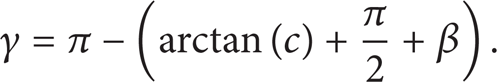
Angle α is signed by Figure 5 and angle γ can be calculated by (20).
The offset along axis X is signed as Δx, the offset along axis Y is signed as Δy, and the rotated angle circling axis C is signed as Δθ caused by grinding force can be calculated by (21) through mechanics of materials:
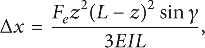


In (23), L is the length of crankshaft and GI p is the torsional rigidity.
The offset of grinding wheel is signed as ∊ x , ∊ y , and ∊θ must be known for compensation and the calculation method is proposed as follows.
Suppose that the radius of the crank pin is r, the radius of the grinding wheel is R, the length of the crank pin center to the original point of coordinate is l, and the angle of crankshaft rotating is θ shown in Figure 8.

Solution of ∊ x , ∊ y , and ∊θ.
Equation (24) can be gained by sine law of triangle:

Equation (25) can be gained by the relations of the right triangle:

From Figure 8, the offsets of grinding wheel can be calculated as shown in

3. Errors Combination and Simulation
3.1. Errors Combination
After the geometrical errors and grinding force errors are calculated, the two types of errors should be combined. To compensation the combinational errors, the precise manufacturing equations containing the errors should be created. The modified NC instructions can be created by the precise manufacturing equations, which include the equations about X and C.
The coordinate of grinding point on crankshaft in inertia coordinate system must be equal to the coordinate of grinding point on wheel in inertia coordinate system by the multibody system. Considering the errors caused by grinding force and the geometrical errors, the precise manufacturing equation is deduced as
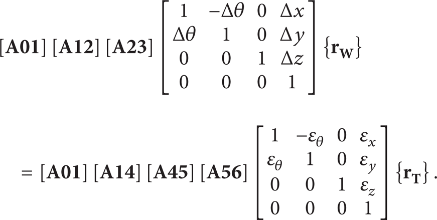
Equation (27) can be simplified as (28). In (28), [

Crankshaft has several crank pins for multicylinder engine usually and the NC instruction generated by (28) has included all axial and circumferential grinding points.
The iteration results of x, z, and θ can be gained by definite step length. The crankshaft can be grinded as required by converting the iteration results to NC instruction and inputting it to machine tool.
3.2. Simulation
3.2.1. Simulation Parameters
One type crankshaft for automobile engine is used for simulation and experiment and its base parameters are as follows. Diameter of grinding wheel is 600.00 mm. Diameter of crank pin is 26.00 mm. Distance between axis of crankshaft and axis crank pin is 53.00 mm. Length of crankshaft is 208.00 mm. Number of crank pins is 4. Central locations of crank pins are 36 mm, 84 mm, 112 mm, and 160 mm. Service life of the machine tool is 10 years. Grinding depth is 10 μm. Grinding wheel material is CBN and its linear velocity is 80 m/s. The crankshaft material is ductile iron. 21 errors of grinding machine tool can be measured and identified by the method of fourteen displacement measurement lines [16]. After 21 errors are gained, the deformation can be calculated and simulation, and compensation can be carried out.
3.2.2. Errors Simulation
To find the errors of axis X and axis C influenced by the wear, deformation, and grinding forces, simulation of errors was carried out and the results were shown as in Figures 9 and 10.
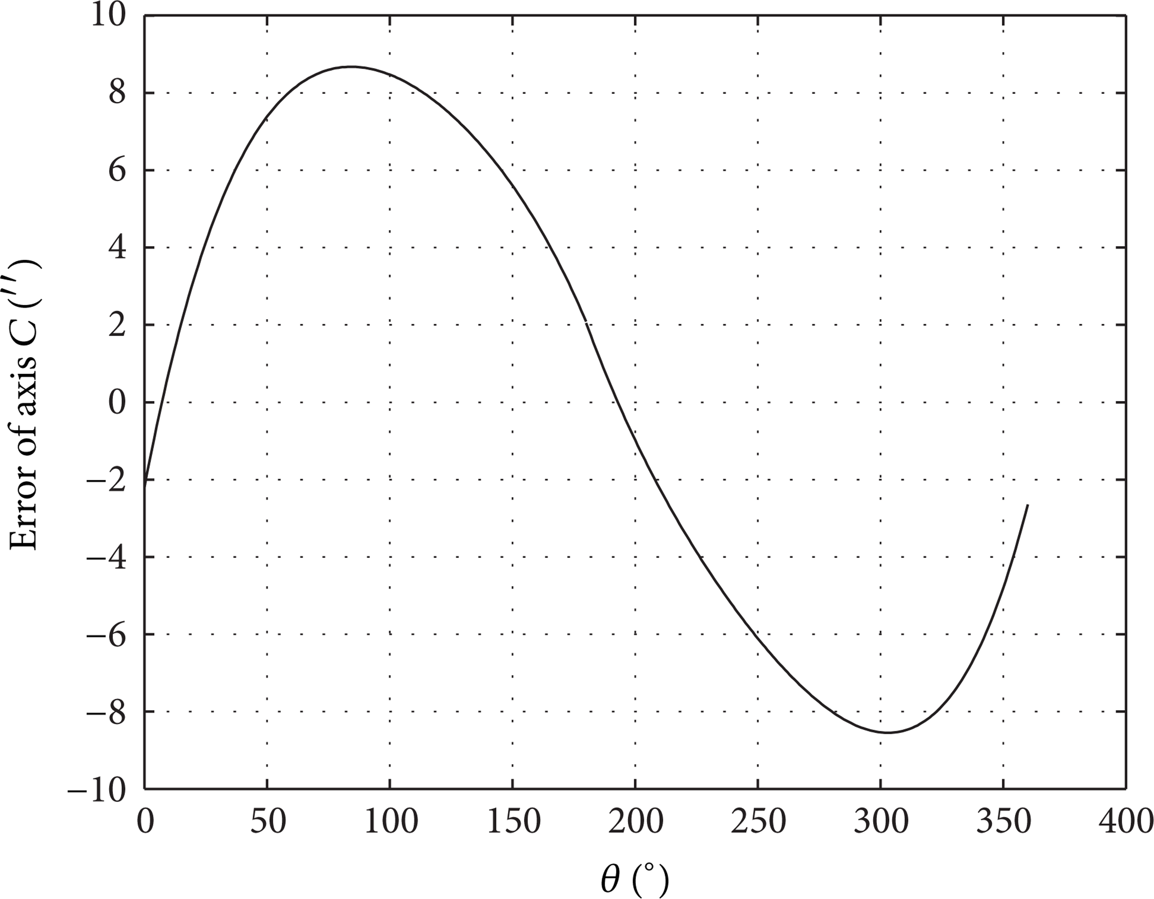
Errors of axis C.
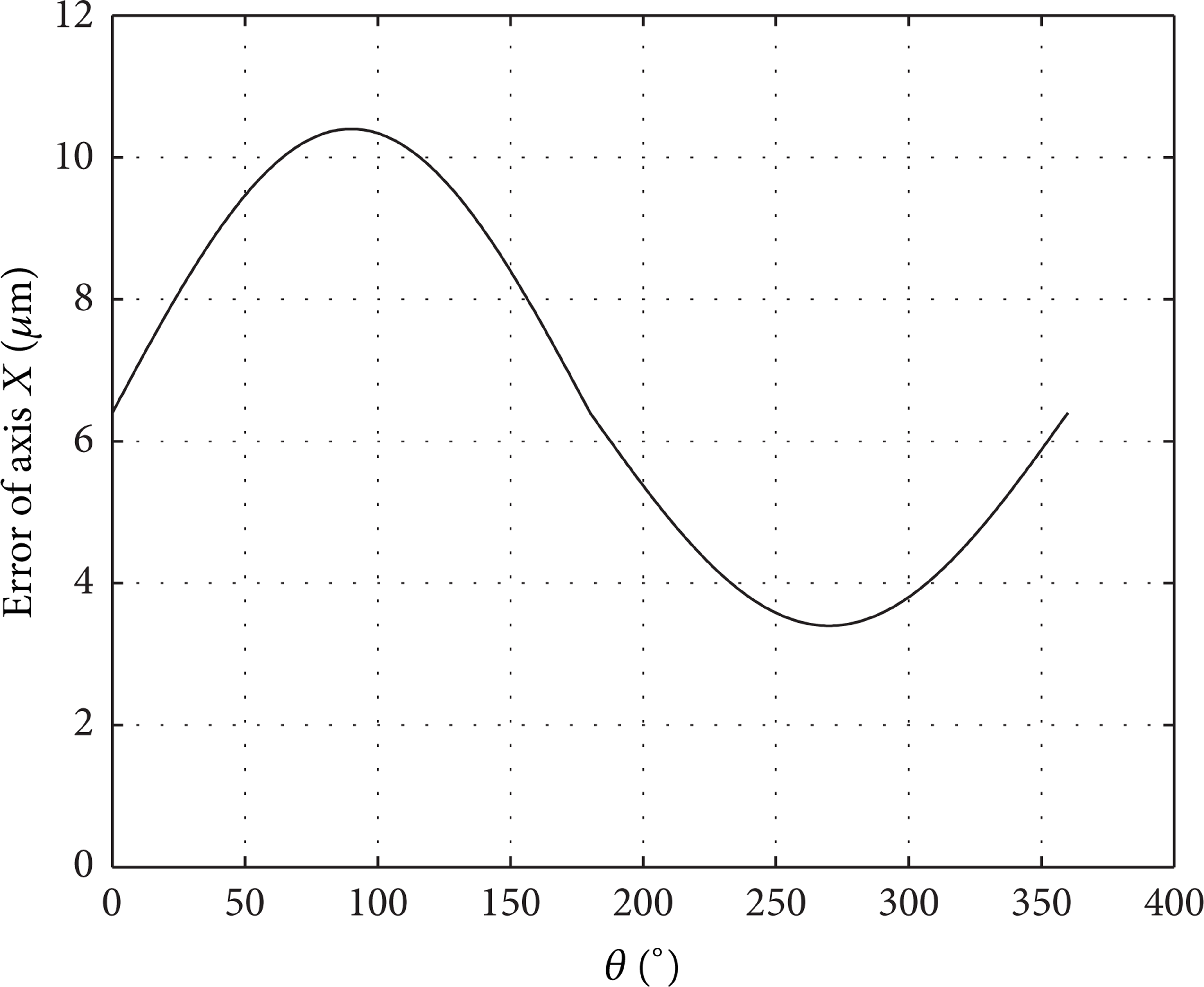
Errors of axis X.
The error of axis C is determined by the resultant's projection on the crank. The bigger the resultant's projection is, the smaller the error of axis C is. The force analysis of special point is as shown in Figure 11. The error of axis C is positive when the real angle exceeds the ideal angle and it is negative when the real angle lags the ideal angle. In Figure 9, the error of axis C is one deformed sine curve. The curve is not symmetrical. The first half cycle is fat and the second half cycle is thin.

Force analysis of special point of the crank.
When θ equals zero, the direction of resultant is down and the error is negative. The error is biggest when θ is about 85° and its value is about 9″. The two half cycles are not asymmetric because the rotation direction of grinding wheel is counterclockwise and the resultant's projection is not equal between the first half cycle and second half cycle.
The error of axis X is determined by the resultant's projection on horizontal axis. The bigger the projection is, the bigger the error of axis X is. The curve is not one strict sine because the projection is not equal in first half cycle and second half cycle. The error is up to being the biggest when θ is 90°. The biggest value of error in the first half cycle is not equivalent to that of second half cycle. All the errors of axis X are positive, which is the reason that the manufactured crankshafts are fat if they are not compensated compared to the ideal dimensation.
4. Experiments and Statistical Analysis
4.1. Experiments
To verify the correctness of analysis and simulation, 10 different experiment types were carried out of different service life, different grinding depth, and noncompensation or compensation, as shown in Figure 12. 30 crankshafts were grinded of each experiment type. The dimension of each crankshaft was measured. The maximal roundness errors of each crank pin were as shown in Figure 13.
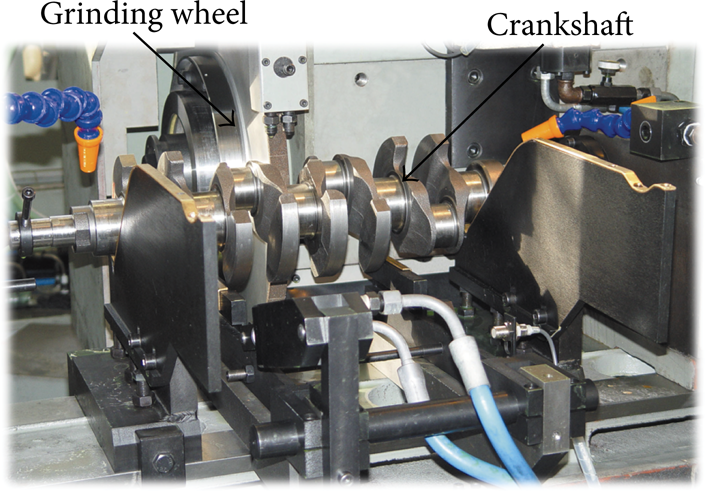
Experiment of crankshaft grinding.

Maximum contour errors.
From Figure 13, compensation for CNC crankshaft grinding machine tool has significant role in the reduction of the maximum roundness error. Also, it is seen that the decrease of maximal error by compensation is not equal to the increase caused by geometry and grinding force. The reason is that it has other factors, such as thermal deformation and servo error, so that soft compensation cannot offset all errors [17–19].
4.2. Interval Estimation
The aim of interval estimation is to verify the maximum error intervals of parts manufactured by noncompensation, compensated and new grinding machine tool under one definite confidence level [20]. Suppose that E1, E2, …, E n are samples of one population, 1 – α is the degree of confidence, E is the sample mean, and S2 is the sample variance. Equation (29) can be gained if the variance of population is not known:

The confidence interval at which the mean value is μ and the degree of confidence is 1 – α can be gained as follows:

The confidence interval of maximum error of the crankshafts manufactured by noncompensation, compensated and new grinding machine tool is calculated by (30) on condition that the degree of confidence is 95% as shown in Table 2.
Comparison of confidence intervals.

It can be seen that the mean value of maximum error after being compensated decreased about 10 μm, which reduced 63.69% than that of noncompensation under the conditions that the service life is 10 years and the grinding depth is 10 μm. The decrease of mean value of maximum error is over 2 μm and the relative decrease is 30.96% if the conditions are that the service life is 4 years and the grinding depth is 6 μm. The allowable roundness error is 20 μm for low quality engine and 10 μm for high quality engine. So, the effect of compensation is significant and important for the grinding machine tool whose machining accuracy has declined.
4.3. Rank Sum Test
To evaluate whether the manufacturing precision was enhanced after compensation and whether the compensation took effect to maintain the precision compared by new grinding machine tool, rank sum test is one common method [21, 22].
Firstly, sort the maximum errors manufactured by three CNC crankshaft grinding machine tools and get the probability density as shown in Figure 14. From Figure 14 it can be seen that the compensated curves are close to the new grinder and far away the noncompensation. That is to say the compensation has significant role in the enhancement of manufacturing precision of the CNC crankshaft grinding machine tool.

Samples maximum roundness errors probability density.
Then, one hypothesis is proposed as follows.
Carry out the Wilcoxon rank sum test between the compensated and noncompensation, compensated and new grinder of different service life, and different grinding depth. The result of wilcoxon rank sum test is P value. If the P value is less than 0.05, which is the confidence level, the hypothesis
P values of Wilcoxon rank sum test.

It can be seen that the P value of the noncompensation and compensated of 10 years of service life and 10 μm grinding depth is 6.09e – 10, less than 0.05, so the hypothesis
It can be concluded that the manufacturing precision will be enhanced significantly by the same analysis manner of different service life and different depth. The longer the service life is and the bigger the grinding depth is, the bigger the maximal error is and the more significant the compensation effect will be.
5. Conclusion
The geometrical errors were analyzed, the precise grinding kinematics equations were deduced, and the NC instruction was compensated and simulated for CNC crankshaft grinding machine tool. Simulation results showed that soft compensation had good effect on enhancing the precision of crankshaft.
The manufacturing experiments of noncompensation, compensated and new grinding machine tool were carried out. The comparison of experiment results showed that the contour precision can be enhanced by 63.69%, 52.06%, 42.27%, and 30.96% under the condition that service life and grinding depth are 10 years and 10 μm, and 4 years and 10 μm, 10 years and 6 μm, 4 years and 6 μm after soft compensation for geometrical errors and grinding force errors. Soft compensation is one effective manner to enhance manufacturing precision for degenerated machine tool.
Conflict of Interests
The authors declare that there is no conflict of interests regarding the publication of this paper.
Footnotes
Acknowledgments
This work was supported by the National Science and Technology Major Project of China (Grant no. 2013ZX04011013) and the National Natural Science Foundation of China (Grant no. 51275014).