
Abstract
Stereo version is a well-known technique for obtaining depth and surface information of objects from images captured by two cameras. In general, this technique is limited by camera occlusion inherent to grooved or steep profiles in 3D shape measurements. To alleviate this problem, a traditional dual-camera system accompanied with a projector based on the stereo vision principle is presented. The projector was considered as a virtual camera. Three sets of stereo vision systems were then obtained with each of the two cameras at the same global coordinates for 3D topography measurements. The data acquisition system constructed with the two real cameras was first calibrated. Then the two-camera-projector system can be calibrated based on the data obtained from the common measurement area of the three systems. Experiments were implemented to evaluate the accuracy of the merging profile integrated from the three sets of stereo vision systems. Experimental results show that the problem of camera occlusion encountered in the original dual-camera system was effectively resolved and a 0.05% error for the height measurement of a ladder-shaped specimen with camera occlusions was obtained in a measurement range of 640 mm × 480 mm.
1. Introduction
Accurate measurement of the 3D shape of objects is a rapidly expanding field, with applications in object recognition, inspection, design, and manufacturing [1]. Among the existing 3D shape measurement techniques, structured light [2] and stereo vision [3] are two of the most commonly used methods due to their advantages such as fast measurement, good accuracy, and noncontact nature. In both techniques, the most pressing concern that limits the measurable range is the camera occlusion introduced by the steep surface or shadow of the specimen. A solution to this problem combined a dual-camera system with structured illumination [4, 5]. This approach utilized two cameras to acquire images independently, so that the measured profile of one view can be extended by combining the measured range of the two cameras and removing the occlusion. However, since the two measured profiles were not based on the same coordinate system, the data integration process for the two different imaging systems is complicated and time consuming.
In this study, a novel stereo vision system consisting of two cameras and a digital projector is presented. The structure is similar to the dual-camera structured light system but the measurement principle is different. In general, through comparison of information about a scene from two vantage points in a stereo version system, 3D information can be extracted by examination of the relative positions of objects in the two panels. Here the use of the light projector has two main functions. First is to reduce the difficulty of the correspondence points searching in stereo matching for the original dual-camera. The second is to model the projector as a virtual camera [6], thereby creating three stereo pairs for each two cameras in the system. The calibration approach proposed by Zhang [7] was adopted for the data acquisition of the stereo vision of the dual camera, and then the calibration of the camera-projector systems can be carried out with the data from the projector itself and the two real cameras based on the stereo vision principle.
After calibration, the 3D data registration can then be executed to transform the 3D data obtained from the three sets of stereo vision systems into a single global coordinate system. Various registration approaches have been proposed, including the iterative closest point algorithm [8], the photogrammetric technique [9], and an additional scanner in the overlapping measurement positions [10, 11]. However, the 3D data merging on existing methods is mostly accomplished through a complicated postprocessing procedure. The 3D data is first calculated and aligned before an overlap region is identified [12, 13]. By using certain algorithms, redundant and overlapping data are then removed and thus multiple sets of data can be integrated into a single group. Therefore a reliable, rapid, and generic 3D registration is still a difficult and open problem. In this investigation, since the three systems were already unified to the same global coordinate, the three corresponding pairs of 3D profiles were automatically well aligned. In addition, an absolute phase-assisted method was proposed for the data merging. The overlapping area of the three sets of stereo vision systems can be clearly identified via the phase-based stereo matching technique and the redundant data can be removed automatically. This simplifies the reconstruction of the 3D information from the three sets of measured data. Experimental results show that the profile in the camera occlusion region of the original dual-camera system was effectively reconstructed in the final integrated surface profile.
2. Measurement Principle and System Calibration
The schematic of the proposed topography measurement system consists of two cameras and a projector as shown in Figure 1. The left camera acquires images of regions I and III, the right camera acquires images of regions I and II, and the projector covers the entire surface of the specimen. As shown, only the 3D shape of region I can be completely resolved with traditional dual-camera stereo vision system. Important surface features on regions II and III are concealed from view due to camera occlusion. However, if the projector is treated as a third camera, then all three regions can be measured. For this reason, the mechanism of using the projector as a virtual camera was developed and this was achieved by a simple calibration process.

Schematic of the dual-camera accompanied with a projector system.
2.1. Calibration of the Dual-Camera System
Figure 2 is the schematic of a traditional stereo vision approach, where C W denotes the three-dimensional world coordinate system, C L and C R are, respectively, the left and right camera coordinate systems, and P W (X W , Y W , Z W ) is the three-dimensional world coordinate for an arbitrary point P in space. The relationships between the world coordinate P W and its corresponding image coordinates P L and P R in the left and right cameras are, respectively,


where λ is a scale factor, A L and A R are, respectively, the intrinsic parameters of the left and right cameras which depend on the position and focal length of the two cameras, R L and t L are, respectively, the rotation and translation matrices between the left camera coordinate system C L and the three-dimensional world coordinate system C W , and R R and t R are, respectively, the rotation and translation relationships between C R and C W .

Optical geometry of a traditional stereo vision system.
Stereo calibration of the dual-camera is the most important process in this system. The calibration result directly influences the measurement accuracy. Numerous calibration methods have been developed which can be divided into two main categories: direct linear transformation method [14] and nonlinear transformation method [15, 16]. In this work, the template calibration method based on a planar checkerboard proposed by Zhang [7] was adopted to obtain the intrinsic parameters (A L , A R ) and extrinsic parameters (R L , t L , R R , t R ) of the stereo vision system. The main advantage of Zhang's approach is that it can obtain the camera parameters by only using few images from few different view angles of the planar template. This method also benefits from high accuracy, fast speed, and robustness.
Once the camera parameters of the dual-camera system are determined, for an arbitrary point P, the relationships between its world coordinate P W and the left camera image coordinate P L (X L , Y L ) and right camera image coordinate P R (X R , Y R ) can be described as


Conversely, the relation between P L and P R is

where R LR = R L R R −1 and t LR = t L – R R −1t R . This means that the position relations between two cameras can be described by a rotation matrix and a translation matrix.
2.2. Calibration of the Projector
Based on the virtual camera idea, a calibration process was implemented to determine the relationship between the world coordinate and the image coordinate of the projector. Similar to the calibration of the dual-camera, a checkerboard pattern was generated with the projector and projected onto the surface of a white flat screen. All the cross-corners of the checkerboard were extracted as sampling points. The world coordinates P W of these sampling points can be determined with the calibrated dual-camera system based on the stereo vision principle. The relationship between the world coordinate P W and the related image coordinate P p in the projector can be seen as

where λ is a scale factor and A p is the projector intrinsic parameter matrix. R p and t p , are respectively, the rotation and translation matrices between the world coordinate system of the checkerboard and the projector coordinate system. These variables also represent the projector extrinsic parameter matrices. Since the pixel positions P p of these cross-corners in the projector are known and the related P W can be found with the dual-camera system, these projector parameter matrices can be easily determined. In addition, similar to (5), the relationship between the left camera image coordinate P L (X L , Y L ) and the projector image coordinate P P (X P , Y p ) can be described as

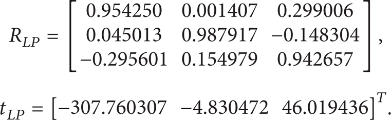
where R LP and t LP are the rotation and translation matrices for the transformation from the projector coordinate to the left camera coordinate, respectively.
3. Three-Dimensional Data Registration and Data Merging
Once the system calibration is completed, the topography measurement of 3D objects can be carried out with the three sets of stereo vision systems. In order to reduce the difficulty in corresponding points matching, an encoded structured light technology is adopted. Similar to the traditional structured light technique, a grating with sinusoidal stripe is projected onto the surface of the specimen by the projector. The deformed grating image is captured by the dual-camera system. The determination of the absolute phase value for each pixel of the cameras is important for the subsequent task in data registration and data merging. This study uses the digital phase-shifting technology to realize the phase distribution of the fringe pattern on the object surface. As shown in Figure 3(a), four sets of gratings with a continuous phase shift amounting to 90° were projected and deformed grating images are captured by the two cameras separately. The phase distribution of the 3D surface profile for each camera can be obtained as

where φ(x, y) is the phase at an arbitrary point (x, y) and I1(x, y) ∼ I4(x, y) represent the four captured image intensities during the phase shift. From (8), the phase is wrapped between the range [– π, + π]. Due to its periodic characteristic, this wrapped phase cannot be directly used for the phase-based stereo matching as it might lead to phase ambiguity. In this study, an unwrapping method combined with the Gray code and digital phase-shifting technology was adopted to acquire the absolute phase value. By assigning the Gray code value of the pattern equal to the fringe order of the grating image, then the Gray code value difference for one period separation of the phase map is 1. Figure 3(b) shows the successive five Gray coded images, where the black region is marked 0 and the bright part is marked 1. The use of five Gray code images can divide the entire field of view (FOV) into 25 regions, each with a unique code value from 0 to 31, such that the Gray code value for each pixel can be obtained. Furthermore, setting the first region to have a Gray code value of zero, and so on, the absolute phase value after unwrapping can be seen as

where φ(x, y) is the initial phase value at each pixel (x, y), G(x, y) is the Gray value of the pixel, and ϕ(x, y) represents the absolute phase value of the pixel.

(a) Four phase-shifting grating images and (b) the Gray coded images.
The absolute phase value of the grating image linearly increases after unwrapping. Based on the comparison of phase value, the stereo matching can be approximately carried out with an accuracy of pixel resolution. Owing to the different viewing angles of the two cameras and possibly surface profile modulation of the object, it is almost impossible to get equal fringe periods from the two images. Therefore, it is in general also very difficult to find pixels that have equal phase value. In this study, the absolute phase value is used as the stereo matching element. Since the absolute phase distribution is linearly increasing, the subpixel stereo matching point with equal absolute phase value can be found through a simple linear interpolation. Let pixels (x L , y) and (x R , y) be the corresponding matching points in pixel resolution, and the related absolute phase values are ϕ L (x L , y) and ϕ R (x R , y), respectively. Assuming that the phase value ϕ L (x L , y) is between ϕ R (x R , y) and the neighboring pixel ϕ R (x R + 1, y), then the corresponding point (x R + δ, y) in the right camera image with subpixel resolution for the pixel (x L , y) in the left image can be found, where δ is the subpixel value and can be obtained as

Accordingly, enough dense disparity can be constructed with the linear interpolation process from the left image to obtain the subpixel stereo matching pairs.
In this system, aside from the images captured with the dual camera, the projected pattern generated in the projector can be considered as the image captured by the projector. As such, three sets of stereo vision systems are constructed and three independent profiles with dense sampling points were obtained using the calculated absolute phase distribution. Since the correspondence between each two cameras was found from the absolute phase value, three sets of measured data can be obtained in a single measurement. However, since the data were independently acquired by three different stereo vision systems, unifying the three measurement data into a common global coordinate system is necessary. Here, the 3D coordinate system of the left camera was chosen as the global coordinate system; it is also the original measurement coordinate system of the dual-camera infrastructure. Consistency of the coordinates can be accomplished easily through coordinate transformation as shown in (5) and (7).
As mentioned, the registration of the measured data can be completed with the obtained absolute phase distribution and a coordinate transformation process. The merging of the three sets of data can be automatically performed. The data measured by the original dual-camera stereo vision system was selected as the base data, wherein common overlapping area among the three systems can be marked off distinctly. Based on the marked region, the full-field profile data of the specimen can be automatically provided by supplementing the measured data from the other two camera-projector systems. Therefore, the original features hidden by camera occlusion region in the dual-camera system can be observed from the matching result.
4. Experiments
The 3D shape measurement system features two black-and-white CCD cameras and a digital light processing projector, as shown in Figure 4. The pixel resolution of the projector is 1024 × 768. The two CCD cameras have identical pixels of 1280 × 960. The focal length of the camera is 12 mm and the distance between the two cameras is 446 mm. The object is placed at a distance of about 1200 mm away from the cameras. Accordingly, the FOV for the measurement system is 640 mm × 480 mm.

Picture of the 3D surface profile measurement system.
Prior to measurements, the stereo calibration of the dual-camera system was first carried out with a black-and-white checkerboard with grids of 25 × 24. The checkerboard contains 24 × 23 = 552 cross-corner points as shown in Figure 5. The nominated grid size of the checkerboard is 15 mm × 15 mm with a machining precision of 0.0025 mm; therefore, the theoretical size of the imaging range covered by the grid points is 345 mm × 330 mm. During calibration, the checkerboard was placed at ten different positions in front of the cameras and the feature points on the board at these positions were separately captured by the two cameras. To get clear image position of the corner points, the checkerboard pattern was set up to occupy 70% to 90% of each image frame. Based on the measured data of these correspondent pairs, the intrinsic parameters of the two cameras from the ten measurements were

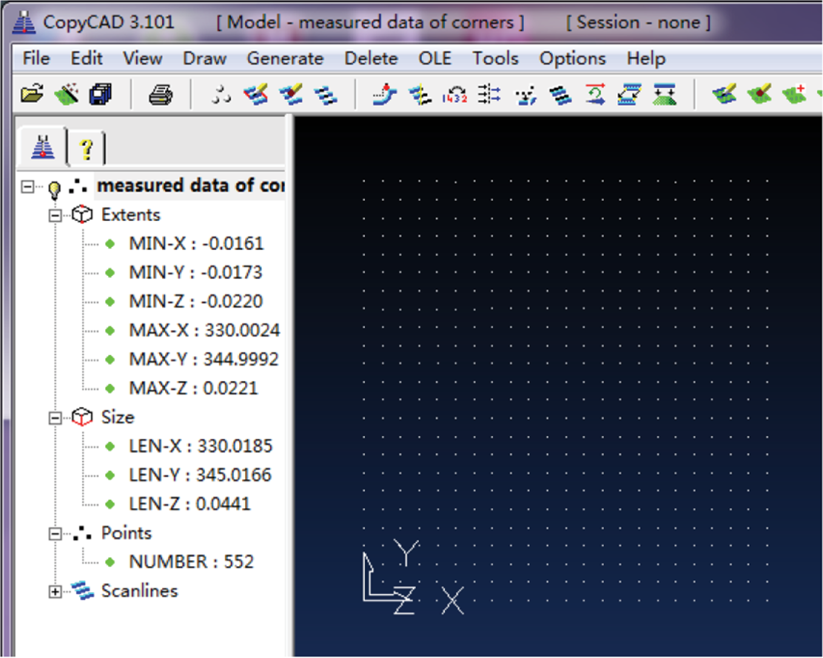
Check of the measurement accuracy of the calibrated dual-camera system.
The extrinsic parameters R L , t L , R R , and t R were changed with the positions of the checkerboard. However, the position parameters R LR and t LR between the two cameras can be determined from the ten sets of data as

For evaluation of the measurement accuracy of the calibrated dual-camera system, the checkerboard was placed at a specific position and the corner coordinates of the checkerboard were determined with the above calibrated parameters. As shown in Figure 5, the measured size of the checkerboard is 345.0185 mm × 330.0166 mm. Compared to the actual size of the board, a lateral error below 0.02 mm was achieved in both X and Y directions. In addition, the resulting error in Z direction was ±0.022 mm. This indicates that a measurement error of roughly 20 μm could be expected with the calibrated dual-camera system.
Calibration of the camera-projector system was implemented by projecting a computer generated checkerboard pattern onto a white flat screen. As shown in Figure 6, the projected checkerboard has a total grid number of 24 × 18 with each grid sized at 30 × 30 pixels. The screen was moved progressively to seven different positions within the measurable range of the dual-camera system. The pictures of the projected pattern at these positions were successively captured with the two calibrated cameras. Again, the picture size of each projected checkerboard was restricted to 70% to 90% of the image size. The 3D space coordinates of these checkerboard corners were extracted through the process of image rectification and stereo matching of the dual-camera system. Based on the 3D coordinates of these feature points in all positions and the known 2D coordinates in the projector and CCDs, the intrinsic parameters of the projector were obtained as


A projected checkerboard pattern captured by two cameras.
In addition, the calibrated transformation parameters between the left camera coordinate and the projector coordinate were, respectively,
Similarly, the transformation parameters between the right camera coordinate and the projector coordinate were

The performance of the proposed virtual camera approach of the calibrated stereo vision system was evaluated on two 3D objects, a ladder-shaped surface object, and a plaster statue. As shown in Figure 7(a), the first object to be profiled was a ladder-shaped surface constructed by combining three gauge blocks with heights of 60 mm, 100 mm, and 50 mm. A sinusoidal fringe was projected onto the surface of the block group and Figures 7(b) and 7(c) are, respectively, the images grabbed with the left and right cameras. As shown, both images emerge where one of the side blocks was hidden from the camera by the shadow of the central block. This clearly shows that only the central block can be measured with the original dual-camera system. Based on the calibrated parameters, the measurement result of the central block is shown in Figure 7(d). Seven points on the top surface as shown in Figure 7(e) were selected to evaluate the height measurement accuracy. The results are shown in Table 1 with a measurement accuracy within 0.016 mm. Measurements were repeated ten times and a repeatability of 0.005 mm was achieved. Figure 7(f) is the final full-field topography of the gauge block group after integration of the measured profiles from each of the three stereo vision systems. As discussed, all of the three profiles were unified to a single global coordinate. The overlapping area can be identified via the phase-based stereo matching and the redundant data can be removed automatically. Similarly, seven separate points on the top surfaces of the left and right gauges were selected as sampling points. The measured heights of the left and right blocks are, respectively, shown in Tables 2 and 3, where the maximum measurement error of the step height was roughly 0.05% of the height.
The measured heights of the seven sampling points of the central block.

The measured heights of the seven sampling points of the left block.

The measured heights of the seven sampling points of the right block.


(a) Schematic diagram of the ladder-shaped specimen. (b) The projected grating image captured by the left camera. (c) The projected grating image captured by the right camera. (d) The measurement result of the central block based on the two-camera system. (e) Seven sampling points on the top surface of the central block. (f) Full-field topography of the ladder-shaped specimen.
The second object to be profiled was a plaster statue with an approximate size of 500 mm × 300 mm. A sinusoidal grating was projected onto the surface of the statue. Figures 8(a) and 8(b) show the images captured by the left and right cameras, respectively. As shown, camera occlusion occurs on both sides of the nose and borders of the statue. Figure 8(c) shows the measured result of the dual-camera system, where the information at the border region of both sides was obviously lost. Figure 8(d) shows the final full-field topography of the statue integrated from the three measured profiles of the three stereo vision systems. The merging result evidently shows that the blank area has been filled and the proposed method can alleviate camera occlusion significantly. Since the statue has a very complex free-form surface, the measurement accuracy is not discussed here.

(a) The projected grating image of the left camera for a statue. (b) The projected grating image of the right camera. (c) The measured profile of the dual-camera system. (d) The data merging result based on the three stereo vision systems.
For the above two experiments, the 3D stereo matching is required for the structured light binocular stereo vision system. In this study the adoption of phase-based stereo matching can automatically identify the overlapping area of the measurement data from different systems and achieve the automatic matching of 3D data. This avoids the search process for the overlapping area as in the traditional method and reduces the difficulty in data integration. Therefore, the computation time for the 3D profile measurement is much reduced. In addition, accurate extraction of the absolute phase determines the accuracy of the stereo matching and also directly affects the accuracy of the measurement. Experimental results show that an accuracy of tens of microns was obtained. This shows that the adoption of the interpolation technique can accurately determine the positions of corresponding stereo pairs, thus ensuring the measurement accuracy.
5. Conclusions
A novel 3D profile automated reconstruction technique for objects with complex free-form surface or step surface is presented. The system consists of two cameras and a projector. The measurement approach is based on the idea that the projector can be considered as a virtual camera; therefore, three stereo vision systems can be constructed to alleviate the problem of camera occlusion effectively. In addition, a 3D data merging method based on the absolute phase value and a unified coordinate system for the three sets of measured data is proposed; therefore, the three sets of 3D profiles can be well aligned and the redundant data can be removed automatically. This avoids the complicated and time-consuming process of data integration in the traditional dual-camera structured light system. Experimental results show that the measurement error below 0.03 millimeters could be expected in the camera occlusion region for a measurement range of 640 mm × 480 mm.
Footnotes
Acknowledgments
This work is supported by the National Key Technology Research and Development Program of the Ministry of Science and Technology of China under Grant no. 2012BAF12B15, the National Natural Science Foundation of China under Grant no. 51175191, the Key Project of Science and Technology Plan of Fujian Province under Grant no. 2008H0095, the Young Scientists Fund of the National Natural Science Foundation of China under Grant no. 51105150, the Natural Science Foundation of Fujian Province 2013J01190, and the Fundamental Research Funds for the Central Universities under Grant nos. JB-ZR1158, JB-ZR1101, and 10QZR11.