
Abstract
This paper investigates experimentally the feasibility of estimating the stress in the prestressing tendons of prestressed concrete bridges using the magnetic field induced by an electromagnet and the Villari effect in which the magnetic susceptibility or permeability of a ferromagnetic material changes when subjected to a mechanical stress. The test results show the good linearity between the stress in the prestressing tendon and the induced magnetic flux density within the practical stress range of the tendons. In addition, the induced magnetic flux density in the tendon appears to depend on the intensity of the electromagnet and the distance between the electromagnet and the tendon regardless of the concrete cover. Accordingly, although further studies are needed for practical applications, the stress in the prestressing tendon of a prestressed concrete bridge can be estimated by measuring the induced magnetic flux density generated in the tendon and by using the linear relationship between this induced magnetic flux density and the stress in the prestressing tendon.
1. Introduction
Prestressed concrete bridges started to be erected effectively worldwide in the 1980s to achieve bridges with spans longer than concrete bridges. The prestressed concrete bridge is a structure in which the deflection or the cracks are reduced by introducing prestress forces through the use of prestressing tendons. Owing to such structural characteristics, the prestress force introduced by means of the tendons has significant effect on the performance of the prestressed concrete bridge. The prestress force of the prestressing tendons experiences changes immediately after its introduction due to not only the loss of prestress but also due to other various reasons during the lifespan of the structure like creep, drying shrinkage, relaxation, and corrosion, which should be managed appropriately through evaluation all along the service life [1]. Failing in the management of the prestress force will result in the increase of the deflection or cracks according to the loss of prestress and lead to severe degradation of the performance or, in worst case, to the collapse of the prestressed concrete bridge [2]. In view of this necessity, diversified nondestructive test (NDT) methods have been studied to estimate the prestress force of the prestressing tendons during the lifespan of prestressed concrete bridges but without successful application on site. In particular, there is practically no example in which economically efficient estimation of the prestress force has been realized for the bonded prestressing tendons applied in existing prestressed concrete bridges.
Research for the estimation of the prestress force in the bonded prestressing tendons applied in existing prestressed concrete bridges can be subdivided into those using system identification (SID), those using guided ultrasonic waves, and those using stress waves. The SID method monitors the change in modal properties in relation to the change in prestress forces. Kim et al. [3] and Ho et al. [4] developed a multiphase SID scheme to detect the occurrence of prestress loss systematically. Kim et al. [5] proposed the vibration and impedance monitoring method to improve the detection of occurrence and location of prestress loss. In general, the SID method has a strong point for overall structural health monitoring but has still limits to estimate the prestress forces locally and directly.
The guided ultrasonic wave method is a NDT method using the vibrational characteristics or propagation velocity characteristics of the ultrasonic wave varying with the stress of the prestressing tendon [6, 7]. This method is widely adopted for the inspection of the cracks or corrosion of pipelines but presents limitations when applied on bonded prestressing tendons. This means that the guided ultrasonic wave experiences loss when penetrating concrete, which makes it difficult to measure the guided wave at distance of merely 1.5 m from the anchorage of the prestressed concrete bridge [6]. Recently, Salamone et al. [7] found out experimentally that the vibrational frequency ratio of the prestressing tendon is proportional to the stress rather than the wave propagation velocity, but this result could not be considered as having solved the loss of the guided wave due to grouting since the experiences were conducted only on specimens shorter than 1.5 m. Considering that most of the prestressed concrete bridges in Korea are longer than 40 m and were erected with bonded prestressing tendons, need is for further research to exploit the guided ultrasonic wave method for the estimation of the stress in prestressing tendons.
Kim et al. [8] estimated the stress in prestressing tendons using the increase of the velocity of the longitudinal stress wave along the tendon according to the prestress force. Differently to the guided wave method, this method enables to measure the stress wave at any position even in bonded prestressing tendons longer than 40 m. However, the sensitivity of the stress to the velocity of the stress wave shows significant degradation at stress level larger than 40% of the yield stress of the tendon. Jang et al. [9] applied successfully this method to estimate the residual stress of the bonded prestressing tendons in the containment structure of nuclear power plants, but this method also necessitates additional improvement to measure accurately the stress in the tendon accounting that the stress in the tendon reaches 50 to 60% of the yield stress under the service load of the prestressed concrete bridge.
The method using the magnetic field can be envisaged for overcoming the disadvantages encountered in the methods using SID, ultrasonic wave, or stress wave. This method uses an external magnetic field to generate an induced magnetic field in the prestressing tendon adopted as magnetic body and applies the Villari effect. The Villari effect, also known as the inverse magnetostriction, was discovered in 1865 by Villari and describes the phenomenon by which the magnetic characteristics like the permeability, μ, of the magnetic body changes according to its stress [10]. Conceptually, the method forms a closed magnetic circuit including the prestressing tendon of the prestressed concrete bridge by means of an external electromagnet and exploits the change in the magnetic flux density, B, of the induced magnetic field flowing in the prestressing tendon according to the stress.
This paper derives a method measuring the prestress force of bonded prestressing tendons in prestressed concrete bridge using the Villari effect and the induced magnetic field generated by an electromagnet. The feasibility of the method is verified experimentally through scaled models.
2. Estimation of the Stress of Prestressing Tendon Using the Villari Effect and Induced Magnetic Field
The relation between the intensity, H, of the magnetic field and the magnetic flux density, B, can be defined by the magnetic permeability, μ, as expressed in the following:

In the physics of magnetic material, the Villari effect, also known as the inverse magnetostrictive effect, is the name given to the change of the magnetic permeability, μ, of a magnetic material when subjected to a mechanical stress [11]. Figure 1 describes conceptually the Villari effect. This is due to the rearrangement of the magnetic domains within the structure of the material. The Villari effect can be either positive or negative depending on the specific material and the intensity of magnetic field (H).

This phenomenon is very effective in amorphous alloys and exhibits outstanding thermal characteristics and durability, which boosted research dedicated to strain gages and torsion gages using such properties [12]. As a typical example, Baudendistel and Turner [13] investigated the change in the permeability, μ, with respect to the stress and temperature of a Fe-Ni alloy and used it to propose an innovative strain gage concept.
As shown in Figure 2, an induced magnetic field is generated in the magnetic body that is the prestressing tendon when a yoke-shaped electromagnet is disposed below the prestressed concrete structure including the prestressing tendon. This layout forms a magnetic circuit in which a magnetic flux, Φ, flows through the electromagnet and the prestressing tendon. The magnetic flux density, B, representing the size of this induced magnetic field in the prestressing tendon depends on the permeability, μ, and the cross-sectional area of the magnetized prestressing tendon and the continuity of the magnetic circuit (closed magnetic circuit). The magnetic flux density, B, crossing the prestressing tendon is measured by a Hall sensor installed on the pole face. The accurate measurement necessitates near magnetic saturation of the prestressing tendon. The continuity of the magnetic circuit depends on the separation between the prestressing tendon and the pole face. Since larger separation results in larger loss of the magnetic flux forming the closed magnetic circuit, a relatively strong electromagnet is required to magnetize the prestressing tendon. In addition, according to Bozorth [14], the intensity of magnetic field (H) changes the sign of magnetostriction of ferromagnetic material and, accordingly, the sign of variation of permeability under stress. So, this effect should be considered for a prestressing tendon, one of ferromagnetic materials. Considering that concrete is a nonmagnetic material, concrete does not disperse the magnetic flux flowing in the prestressing tendon and the concrete cover has practically no effect. Fernandes et al. [15, 16] exploited the fact that the magnetic flux density of the magnetic field is influenced by the cross sectional area of the prestressing tendon to measure the degree of corrosion of the tendon in a prestressed concrete structure.
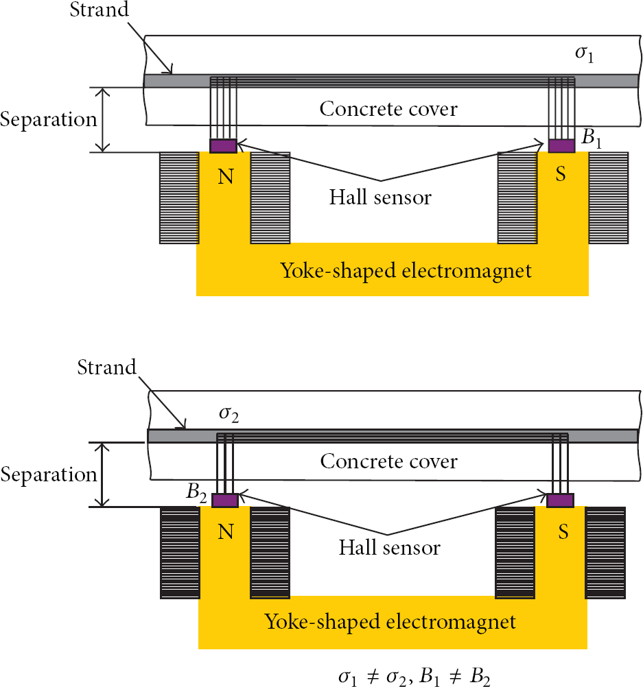
Illustration of induced magnetic fields in tendons of different stresses.
Therefore, since the permeability, μ, of the prestressing tendon subjected to stress varies according to the stress when the tendon is magnetized by means of a permanent magnet or an electromagnet with a magnetic field intensity, H, the density, B, of the magnetic flux flowing in the tendon will vary with respect to the stress owing to the Villari effect. Even if the cross sectional area of the tendon decreases under larger stress due to the Poisson's effect, this effect can be assumed to be relatively insignificant. Consequently, the measurement of the magnetic flux density, B, flowing in the tendon will enable to estimate the stress of the tendon by comparison with the stress of the tendon that has been preliminary measured and the magnetic hysteresis loop
3. Model Test for the Proposed Method
3.1. Summary of Test
The feasibility of the method measuring the stress of the prestressing tendon by means of the Villari effect and the induced magnetic field is examined experimentally by measuring the relation between the stress of the tendon and the induced magnetic flux density.
Figure 3 illustrates the concept underlying the test. A loading device and a frame are prepared so as to vary the stress of the tendon during the test, and an electromagnet is disposed at a position below the tendon to secure definite separation. Two Hall sensors are installed on the face poles of the electromagnet to measure the magnetic flux density, B.

Illustrative layout for the test.
The loading frame for the prestress of the tendon was fabricated using 100 × 100 mm H-beam (Figure 4). Loading was applied by means of a hydraulic nut (Figure 5). The introduced prestress force was measured using a center holed load cell with capacity of 50 ton disposed between the loading frame and the hydraulic nut (Figure 5). The temperature of the tendon during the test was measured by a thermosensor attached to the tendon and the ambient temperature by a digital thermometer.

Test setup.

Multimeter, load cell, and hydraulic nut.
The electromagnet used to induce the magnetic field in the tendon was fabricated to provide a maximum magnetic induction of 4000 Gauss at the pole face (Figure 6). Two Hall sensors (model WSH135 of Winson) are attached at the centers of N-pole and S-pole for measuring the magnetic flux density (Figure 7). The voltage occurring at the Hall sensor is measured by means of a multimeter (model 34410A of Agilent) (Figure 5).

Prestressing tendon and installed Hall sensor, thermosensor, and electromagnet.

Hall sensor installed at the N-pole of the electromagnet.
In order to examine the effect of the concrete cover on the magnetic flux density, tests were performed using a movable concrete plate device disposed at the bottom of the tendon (Figures 8 and 9). The thickness of the concrete plate is 22.7 mm.

Case with concrete cover.

Case with removed concrete cover.
Using this experimental setup, the magnetic flux density or magnetic induction, B, induced in the tendon by the electromagnet was measured by varying the stress of the prestressing tendon. Referring to the Korean Highway Bridge Design Code (2010) [17], the stress of the prestressing tendon was varied from 14% of the yield stress to a value of 80% of the yield stress close to the tensile allowable stress of the tendon immediately after the introduction of prestress. The tendon adopted for the test is SWPC7B tendon (7 strands of 15.2 mm) widely used for prestressed concrete structures. The input current determining the intensity of the magnetic field and the separation, which is the distance between the pole face of the electromagnet and the bottom of the prestressing tendon, was decided so as to magnetize the tendon to near saturation level. The variables used in the test are arranged in Table 1.
Test variables for the test.

3.2. Measurement of Magnetic Saturation of Prestressing Tendon
Prior to investigate the relation between the stress and induced magnetic flux density in the prestressing tendon, the input current of the electromagnet was varied to find the input current and separation enabling to magnetize the tendon to near saturation level. Comparison of the magnetic flux densities of the electromagnet was conducted for the cases corresponding to the absence of tendon and corresponding to the tendon without prestress. In addition, the induced magnetic flux density of 1 wire of 5 mm diameter composing the tendon was also measured to test the effect of the cross sectional area of the tendon on the magnetic induction. For both cases, the separation was set to 40 mm.
In view of the test results in Figure 10, when the input current of the electromagnet ranges between 0 to 3.67 A, the difference between magnetic flux densities of electromagnet and the prestressing tendon, that is, the increased magnetic flux density due to the presence of the prestressing tendon, tends to increase with the varying input current. However, for input currents larger than 3.67 A, this increase converges to a constant value. This means that near magnetic saturation of the tendon can be achieved for input current larger than 3.67 A in the case of a separation of 40 mm. Besides, for the wire with diameter of 5 mm, difference could practically not be observed between the cases where there was only the electromagnet and where the wire was present. This observation can be attributed to the fact that near magnetic saturation is easily achieved for small cross sectional areas.

Magnetization of the prestressing tendon to near saturation.
3.3. Measurement of the Induced Magnetic Field of the Prestressing Tendon
Referring to Figure 10, the input current of the electromagnet was set to 4 A and 5 A. The separation was decided as 25 mm and 46 mm (practically close to 25 mm and 46 mm, resp.) considering the cover thickness in real concrete structures. During the tests, the variation of temperature remained insignificant. During the tests with separation of 25 mm, the ambient temperature was 23.5°C (4 A) and 23.7°C (5 A), and the temperature of the tendon ranged between 22.6 and 23.3°C for input currents of 4 A and between 22.9 and 23.8°C for input currents 5 A. During the tests with separation of 46 mm, the ambient temperature was 21.8°C (4 A) and 22.9°C (5 A), and the temperature of the tendon ranged between 21.4 and 21.8°C for input current of 4 A and between 22.6 and 22.8°C for input current of 5 A.
In view of the test results for a separation of 25 mm in Figure 11, a highly linear relationship can be observed between the stress of the tendon and the induced magnetic induction B for both input currents. The linear regression of the relation between the stress of the tendon and the induced magnetic induction reveals a coefficient of determination (

Stress of prestressing tendon versus magnetic induction B (separation of 25 mm).
From the test results for a separation of 46 mm in Figure 12, the highly linear relationship between the stress of the tendon and the induced magnetic induction appears also for the input currents of 4 A and 5 A with coefficients of determination (
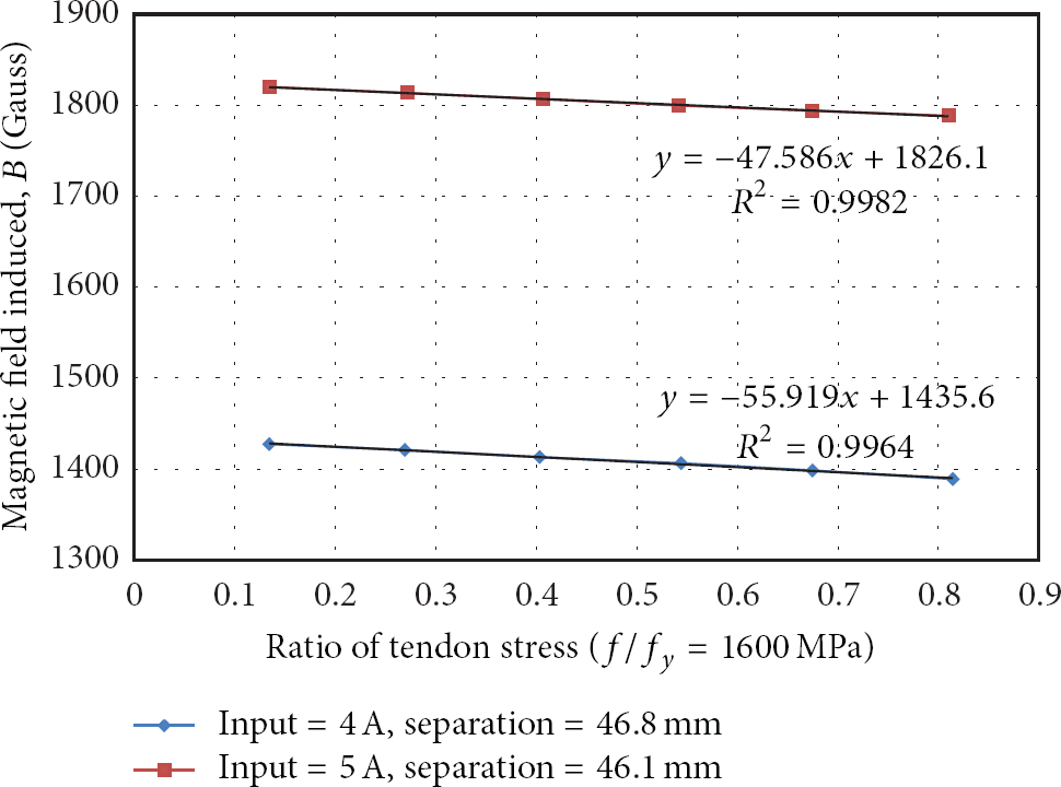
Stress of prestressing tendon versus magnetic induction B (separation of 50 mm).
The relation between the separation and magnetic flux density induced in the tendon for the input current of 5 A was examined (Figure 13). The magnetic induction is seen to reduce by 281 Gauss in average according to the increase of the separation from 25 mm to 46 mm.
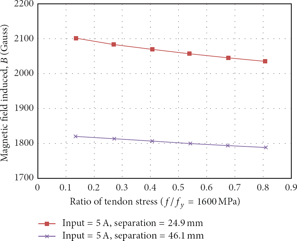
Reduction of the magnetic induction according to the separation.
Figure 14 plots the results of the tests investigating the relation between the thickness of the concrete cover and the induced magnetic induction for the input current of 4 A and separation of 46 mm. It appears that the cover made of nonmagnetic concrete has practically no effect on the magnetic flux density induced in the tendon. Despite of slight change in the magnetic induction B due to the concrete cover, this change remained within the measurement error occurring during the measurement of the voltage of the Hall sensors, which means that the concrete cover has practically no effect on the magnetic flux density.
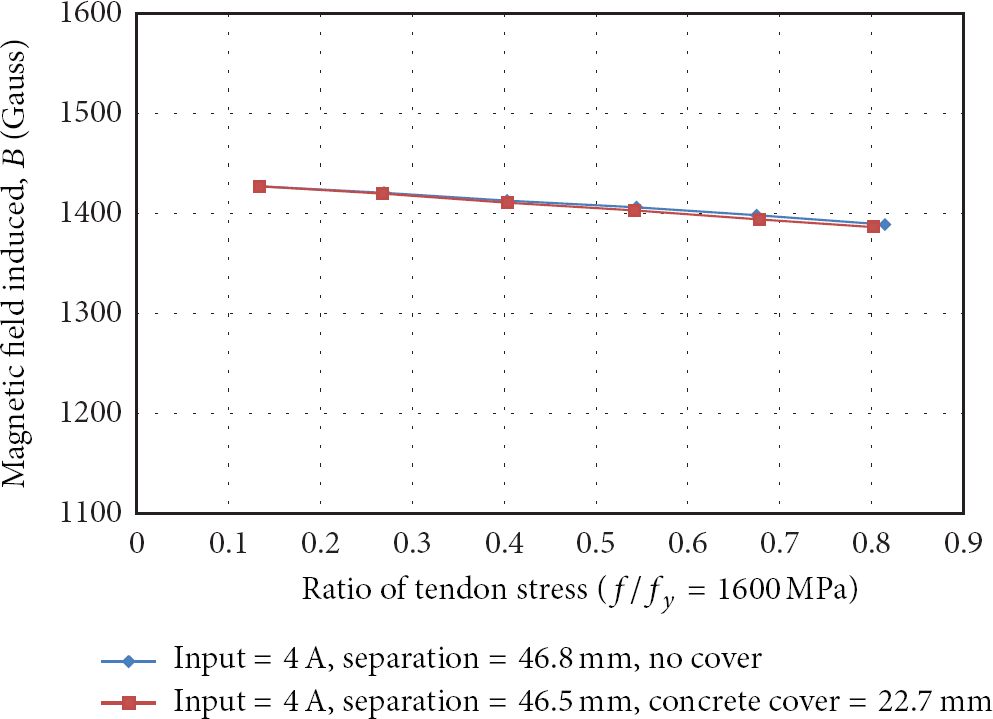
Relation between the concrete cover and the induced magnetic induction B.
4. Conclusions
This paper investigated the feasibility of the method estimating the stress in the bonded tendon of prestressed concrete bridge using the Villari effect and the induced magnetic field. To that goal, a magnetic field was generated in the prestressing tendon by means of an electromagnet and the relation between the stress of the tendon and the so-induced magnetic flux density was observed. The test results revealed that, within the stress range (from 0.14
Accordingly, this linear relation between the stress of the tendon and the induced magnetic flux density can be used to estimate the stress of the bonded prestressing tendon in existing prestressed concrete bridges. This means that if Hall sensors are used to measure the magnetic flux density induced in the prestressing tendon by an external electromagnet attached to the prestressed concrete bridge, the stress of the tendon can be estimated by the Villari effect in which the magnetic permeability varies according to the stress of the magnetic body. However, additional studies should be conducted for further practical application of the method. Concretely, the magnetic
Footnotes
Acknowledgment
This research was supported by a grant from a Strategic Research Project (Diagnostic Techniques for the Prestressing System in Concrete Bridges) funded by the Korea Institute of Construction Technology.