
Abstract
Optimum design is a pivotal approach to fulfill the potential advantages of the parallel manipulator in practical applications. This paper concerns the optimum design issue of the 3-3 Stewart platform considering the inertia property, in addition to the kinematic performance. On the basis of spherical usable workspace, global conditioning index (GCI) is analyzed. Atlases of the workspace and GCI are deduced with the established nondimensional design space. Further, after dynamic modeling, the global inertia index (GII) is deduced from the joint-space inertia matrix, and corresponding GII atlases are drawn. In particular, an example is presented to illustrate the process of obtaining the practical optimum results based on these non-dimensional atlases. Since both kinematic and dynamic properties are considered, the optimum result will possess comprehensive performance improvements.
1. Introduction
The parallel manipulator usually consists of the base and the end effector, which are connected together with at least two identical kinematic chains. Its significant structure feature is the closed-loop kinematic chain. Compared with conventional serial manipulators, parallel manipulators possess some inherent potential advantages [1], such as high accuracy, improved stiffness, increased dynamics, compact structure with multiple degree of freedoms (DOF), and so on. As a result, parallel manipulators attract great academic attentions and are more and more widely adopted in industrial applications, namely, flight simulators [2], telescopes [3–5], and machine tools [6].
Optimum design of the parallel manipulator is recognized as an important theoretical issue, as well as a great practical approach to make full use of its potential advantages in practical applications [7, 8]. Optimization design of the parallel manipulator is always a challenging issue, which is mainly based on the kinematics now [9]. And several kinematic performance criteria could be involved, such as workspace [10], singularity [11], accuracy [12], stiffness [13], and conditioning index [14]. Among them, workspace and conditioning index are the two most important key criteria. On the other side, the dynamic performance of the parallel manipulator is analyzed and evaluated in a lot of works [15, 16]. However, little effort has been made on the dynamic optimum design.
Inertia property is an important part of the manipulator dynamics, which shows its impacts in many ways [17, 18], such as mechanical resonance frequency, acceleration capability, and dynamic response. Inertia property has been invested on both serial manipulators and parallel manipulators [19, 20]. The inertia index of parallel manipulator is proposed in [21], which gives accurate and concise description of the inertia property of the parallel manipulator. In this paper, in addition to kinematic criteria, the inertia index is adopted to carry out the optimum design of the parallel manipulator, which helps us to obtain the optimum results considering both dynamic and kinematic performances.
The study object of this paper is a 3-3 Stewart parallel manipulator, which is also called the octahedral platform [22]. Generally, the Stewart platform is a 6 DOF spatial parallel mechanism [23], which is composed of two bodies (the end effector and the base) and six extensible limbs. Each limb, driven by a set of servomotor and ball screw, is connected with the base by a universal joint at one end and the end effector by a spherical joint at the other end. The 3-3 Stewart manipulator contains three concentric spherical joints and three concentric universal joints. This special construction usually possesses better kinematic performance and larger workspace, which also makes closed-form direct kinematic solution feasible [24].
The remainder of this paper is organized as follows. In the next section, kinematics is analyzed, based on the established coordinate systems. Workspace and conditioning index atlases are obtained in Section 3. In order to obtain the inertia index, the dynamic model is deduced briefly in Section 4. The global inertia index is defined, and corresponding performance atlases are given in Section 5. In Section 6, atlases base optimum design of the parallel manipulator is carried out, considering kinematics as well as dynamics. Finally, conclusions are listed in Section 7.
2. Kinematics and Jacobian Matrix
As shown in Figure 1, the base of the 3-3 Stewart platform is represented by three pairs of concentric universal joints, located at points B1 = B6, B2 = B3, and B4 = B5. And the end effector is defined by three pairs of concentric spherical joints, marked with points P1 = P2, P3 = P4, and P5 = P6. To facilitate analysis, a fixed Cartesian coordinate system
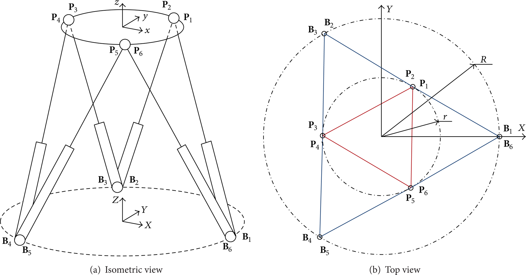
Kinematic model of the 3-3 Stewart platform.
For convenience, important notations adopted in this paper are shown in Table 1. Generally, vectors and matrices are expressed in bold, while numeric variables are described in italic. Left superscripts of symbols indicate the coordinates systems where the physical quantities are described.
Notation description.
Position of the end effector can be described by the translation vector

with its developed expression
where s stands for the sine operation and c stands for the cosine operation.
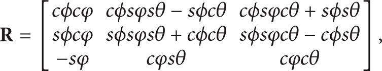
According to kinematic schema of the limb shown in Figure 2, the closed-loop position vector equations can be written with rotation matrix and translation vector as

where
Kinematic schema of the ith limb.
Taking the time derivation of (3), the velocity mapping function can be deduced in the base frame as

where the skew-symmetric matrix operator

expressed in the fixed base frame {
At the same time,

where
Considering (4) and (6) together gives the relation between the end-effector velocity and the limb velocity as

Further, using the projections of six vector relations of (7) along the direction of six legs B i P i , after organization, we obtain the following matrix form:

where

3. Kinematic Performance Atlases
3.1. Design Space
Considering the applicability in engineering, the generalized symmetric structure is adopted to carry out the optimum design of the 3-3 Stewart platform. In other words, both spherical joints and universal joints are circumferentially uniformly distributed. Accordingly, the architecture of the object 3-3 Stewart manipulator can be described by four geometric parameters. As shown in Figure 1(b), two parameters are distribution radii of rotational joints R and r. The initial height h between the base and the end effector can be used as the third parameter, when the end effector is at the central configuration with half-stretched limbs. The fourth parameter is the limb length ratio ζ, the proportion of the maximum length, and the minimum length, which can be obtained with practical engineering experiences. In this paper, ζ = 1.5. Then, the architecture of the object 3-3 Stewart platform can be totally defined by three length parameters, namely, R, r, and h.
In order to embody all possible combinations of these three parameters in a finite area, parameters need to be normalized and physical dimensions must be eliminated. Define a dimension factor η and

Then, three dimensionless parameters l i (i = 1, 2, 3) can be obtained as

To facilitate further analysis, parameters are illustrated in two-dimensional plane, as shown in Figure 3. l1-axis is parallel with the Y-axis, l2-axis and l3-axis are perpendicular to each other, and the angle between l1-axis and l2-axis is 3π/4. Theoretically, these three dimensionless parameters can take any value from 0 to 3. However, for the Stewart platform, the distribution radius of the end effector r should be no larger than the base distribution radius R. Thus, the available design space is under the line of R = r and marked with red lines in Figure 3.

Design space.
3.2. Workspace Atlas
In order to carry out the workspace analysis, let us adopt the Spherical Usable Workspace (SUW), which can be defined as the maximum continuous spherical workspace without singularity locus. Usually, the SUW of the Stewart manipulator is the maximum inscribed sphere of the reachable workspace, encircled with twelve envelope surfaces.
For the Stewart platform, there is only the second type singularity, which can be further classified into three categories, namely, architecture singularity, configuration singularity, and formulation singularity [25]. Without huge end-effector rotation (± π/2), only the configuration singularity when the base and the end effector coincide may appear for our object Stewart platform.
The radius is used to represent the size of the SUW and to draw the workspace atlas. Without considering the end-effector rotation, the SUW atlas is deduced and shown in Figure 4. We can find that
in the left region of the design space, radius of the SUW is generally proportional to l3(h). In this area, the SUW radius is mainly limited by the singularity condition. In other words, the SUW cannot intersect with the plane of Z = 0;
in the middle part, radius grows with the shrink of the l1(r) approximately;
in the right area, radius curves are almost parallel to the l2-axis. When l2(R) is specified, the SUW radius increases with the enlarging difference between l1(r) and l3(h);
the relative larger SUW appears at the lower parts of design space, where the value of l1(r) is smaller.
Atlas of the zero-rotation spherical usable workspace.
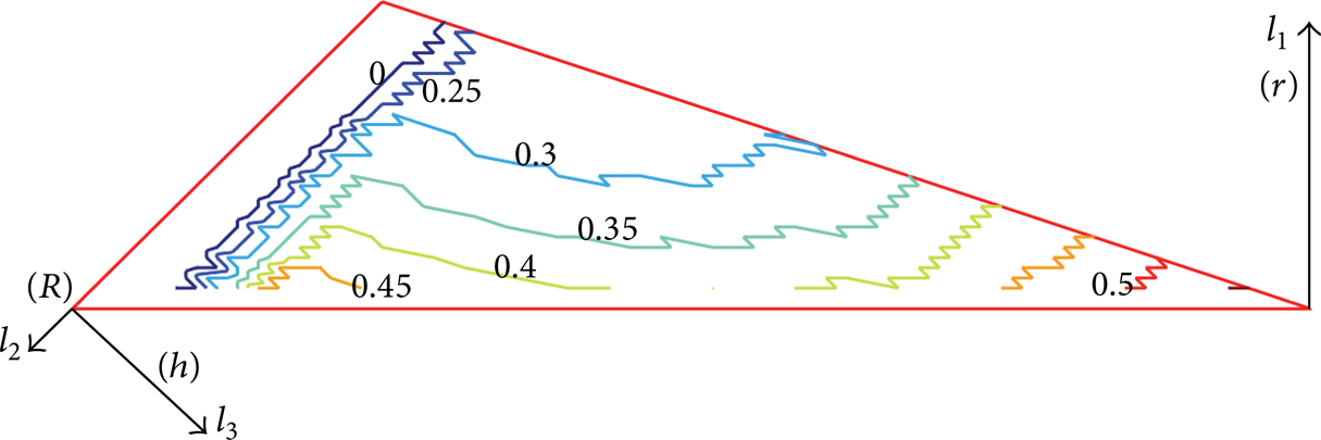
3.3. Atlases of Global Conditioning Index
The condition number κ of the Jacobian matrix proposes a measure of the control accuracy of the manipulator, which is also used to evaluate kinematic isotropy and dexterity of the manipulator. The condition number should be kept as small as possible to obtain good kinematic performance. Its reciprocal 1/κ is usually called the local conditioning index (LCI), which is configuration dependent. Further, the global conditioning index (GCI) is defined to evaluate the global behavior in the entire workspace, which can be expressed as

where W is the SUW of the parallel manipulator. And larger GCI value promises better control accuracy and kinematic performance generally.
The dimensional homogeneity of the Jacobian matrix is obtained by adopting the distribution radius of the end effector as the characteristic length. Each element in lower three rows of the Jacobian matrix is divided by the characteristic length. Then, the GCI atlas for our object manipulator is obtained and shown in Figure 5, from which we can conclude that
the design space can be subdivided into three regions with lines of r = h and R = h;
in region I, GCI curves are almost parallel to the l2-axis, and GCI value grows with the increase of l3(h) (or decrease of l1(r));
regions II and III are approximately symmetrical about the line of R = h;
the maximum GCI value appears around the midpoint of the R = h line (l1 = 0.64, l2 = l3 = 1.18).

Atlas of global conditioning index.
4. Dynamics and Inertia Matrix
The joint-space inertia matrix is the fundamental to deduce the inertia index, which can be derived from the dynamic model. In this paper, the virtual work principle [26] is adopted to establish the dynamic model of the object Stewart manipulator. The concise expression of the joint-space inertia matrix is obtained, based on the limb Jacobian matrices.
4.1. Limb Jacobian Matrices
Limb Jacobian matrices describe the relation between limb velocities and the end-effector velocity. As shown in Figure 2, limb local frame
Equation (4) can be expressed in the limb local frame

where
Accordingly, the sliding and angular velocities of the limb can be deduced from (6) in the limb local frame


Further, the linear velocity of lower and upper part centroids in the ith limb can be expressed as


where
4.2. Acceleration
Acceleration parameters can be deduced by taking the time derivation of (14), (15), (16), and (17) as
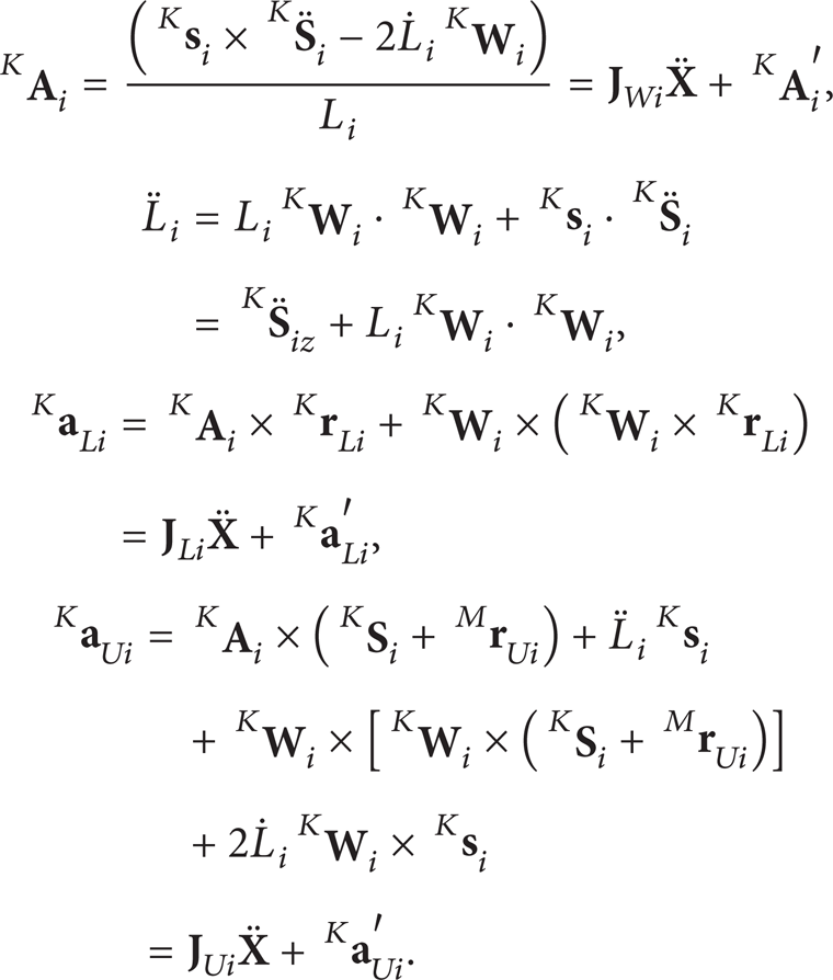
The acceleration of end-effector mass center can be expressed in the base frame as

where
4.3. Dynamic Model
In this part, inertia force and torque of the end effector are given in the base frame {

where
The force and inertia exerted to the ith lower part limb about its mass center can be deduced in the limb local frame

where m
L
is the lower part mass and
The inertial force and moment of the upper part limb about the mass center can be written in

where m
U
is the upper part mass and
Given a virtual displacement δ

where
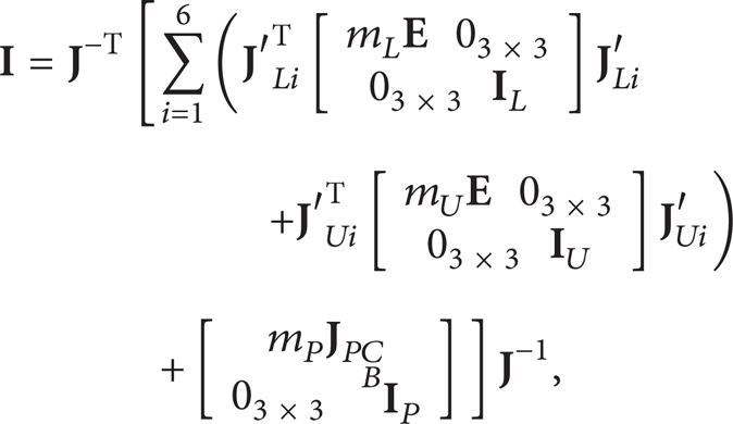
where
5. Global Inertia Index and Atlases
The inertia index is the mean of eigenvalues of the joint-space inertia matrix, which can show the load characteristics. The inertia index is important to evaluate the dynamic performance of the parallel manipulator. In particular, a small value of the inertia index ensures that the manipulator could possess high mechanical resonance frequency, good dynamic accuracy, and high acceleration capacity.
The inertia index is also dependent on configuration of the manipulator and is a local performance index, which can be called as local inertia index (LII). In order to study the global performance of the manipulator within the workspace, the global inertia index (GII) can be defined as

Parameters λ
i
and I
ii
are the eigenvalues and main diagonal elements of the joint-space inertia matrix
In order to facilitate practical applications, the GII atlases of different parts are illustrated separately, such as the end effector, upper part limbs, and lower part limbs. The GII atlas for the end effector is shown in Figure 6, and the inertia and mass parameters of the end effector are given as m
P
= 10 and
the minimum value of GII appears in the place where l1, l2, and l3 equal 0.86, 1.28, and 0.86, respectively;
in the middle region of the design space, there is a quite large area where the GII value is relatively small;
in most area, the GII value grows with the decrease of l1(r) and the increase of difference between l2(R) and l3(h);
with the parameter point approaching the lower left corner or the right corner, the GII value grows sharply.
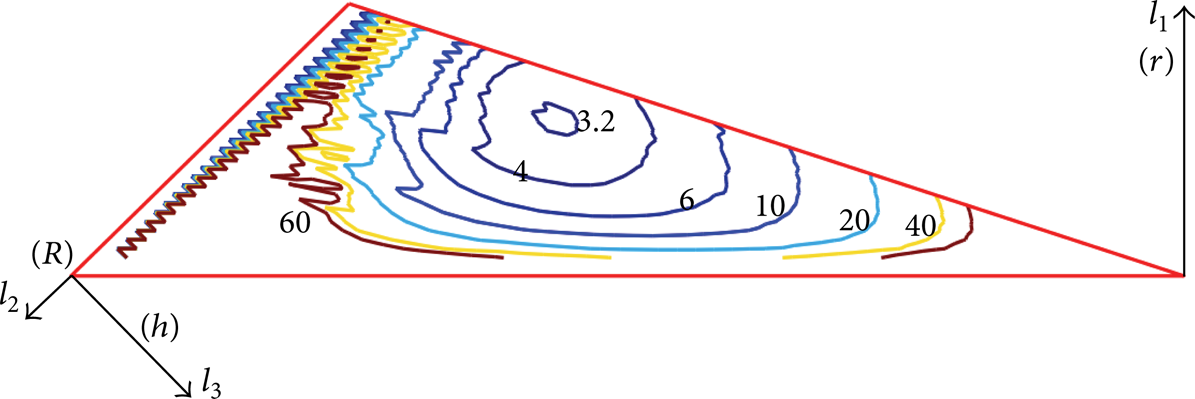
Atlas of global inertia index for the end effector.
Let us assume that limbs of the Stewart manipulator are thin-walled cylinders. Then, mass and inertia parameters of upper and lower parts of the limb can be deduced with the given line density, which can be obtained from engineering experience and size estimation. Here the unit line destiny is adopted. GII atlases for the lower and upper parts of the limb are shown in Figures 7 and 8, respectively. We can discover that
distributions of the GII for the upper and lower parts are similar;
the manipulator with the best limb GII is in the middle of the design space, while the largest limb GII is located at the lower left and right corners.

Atlas of global inertia index for the lower part limbs.

Atlas of global inertia index for the upper part limbs.
6. Atlases Based Optimum Design
Based on performance atlases obtained above, we can clearly see the performance trends and realize the performance of 3-3 Stewart manipulator with any combination of l1, l2, and l3. Besides, the rationality of the optimum goal can be recognized easily. In this section, the optimum design is carried out. The first step is to determine the performance requirements and to draw corresponding performance atlases, which has already been accomplished above.
The second step is to obtain the candidate region for the optimum design. Let us consider the kinematic performance only, at first. For example, if the zero-rotation SUW radius is not less than 0.3 and GCI value is not less than 0.55, then the candidate region can be determined as shown in Figure 9. Parameter ranges in this region can be obtained as l1 ⊂ [0.33, 0.66], l2 ⊂ [1.13, 1.44], and l3 ⊂ [0.97, 1.34]. In the candidate region, the manipulator can meet the desired workspace and condition number requirements.
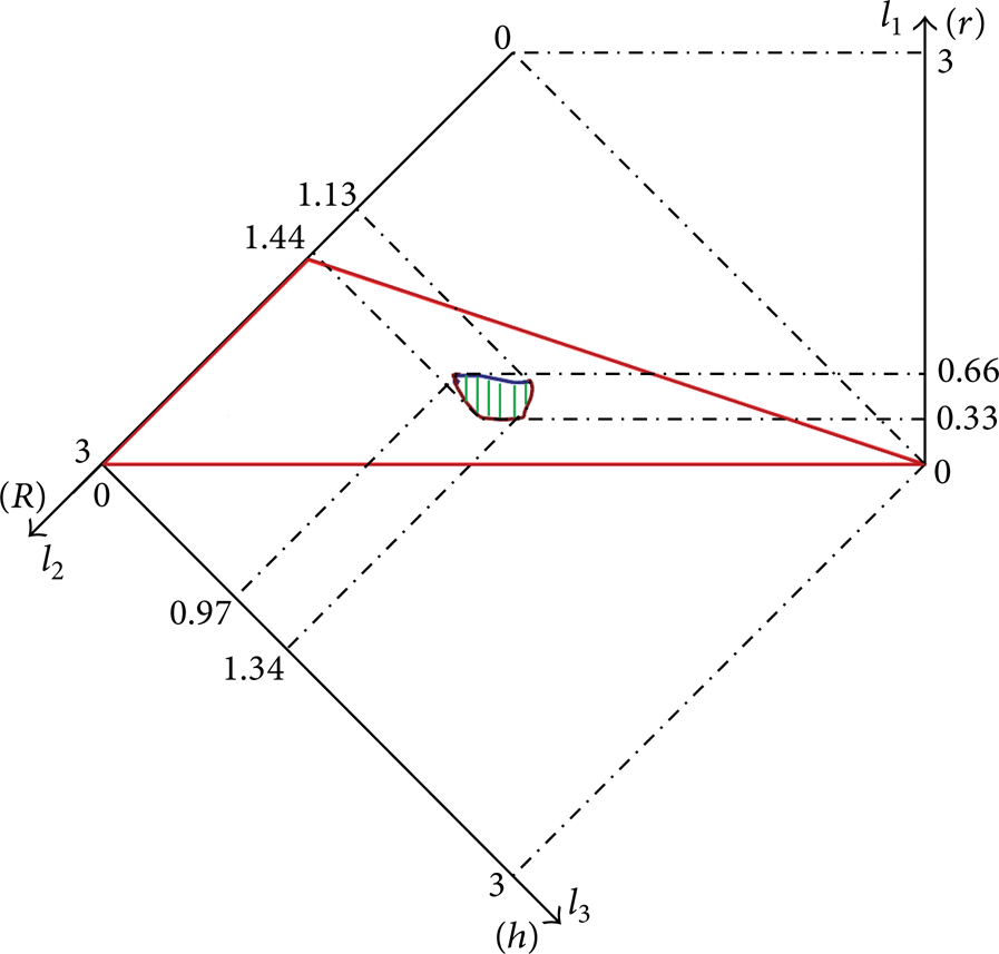
Candidate region considering kinematics.
Then, the inertia index is considered on the basis of the above kinematic requirements. Usually, the Stewart manipulator is under heavy duty, and the inertia parameter of the end effector (include the load) is dominant. Under this assumption, only Figure 6 is considered here. If the GII value is required less than or equal 4, the deduced candidate region is shown in Figure 10. Corresponding parameter ranges are l1 ⊂ [0.48, 0.66], l2 ⊂ [1.16, 1.42], and l3 ⊂ [0.97, 1.22]. Compared with the above result only considering kinematic performance, the candidate region is reduced, and parameter ranges shrink accordingly. In this candidate region, the manipulator has the desired dynamic performance as well as the desired kinematic performance.
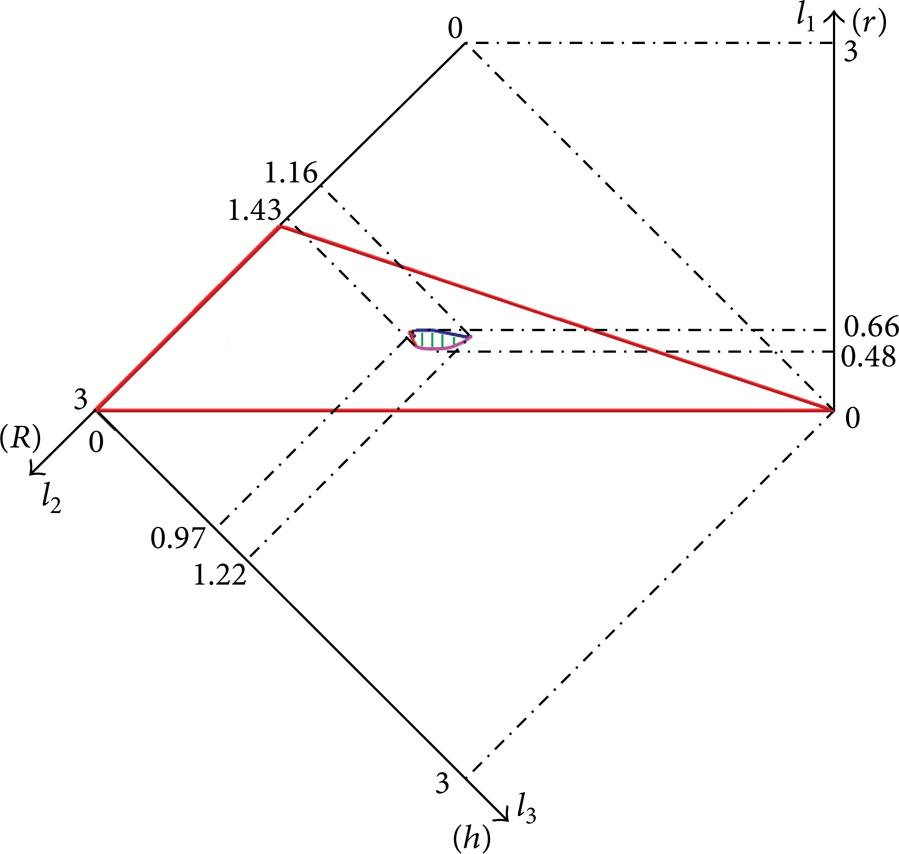
Candidate region considering both kinematics and dynamics.
The next step is to determine a set of optimum parameters, in view of the most desired performance or engineering conditions. In order to demonstrate the process, we consider the manipulator with l1 = 0.66, l2 = 1.37, and l3 = 0.97 to obtain the minimum GII value within the candidate region, for example.
At the last step, the dimension factor η is determined, and the actual parameters of the manipulator can be obtained. The dimension factor can be determined by the workspace requirement or some specific local index. For example, if the objective workspace radius is 0.3 m, the dimension factor can be obtained as η = 1 m. Then, the practical dimensional parameters can be figured out as r = η × l1 = 0.66 m, R = η × l2 = 1.37 m, and h = η × l3 = 0.97 m. With the given limb length ratio ζ, limb length can also be determined.
7. Conclusions
In this paper, optimum design approach for the parallel manipulator, which considers both kinematic and dynamic performances, is proposed. The nondimensional design space is established. In kinematics, the spherical usable workspace and the global conditioning index are investigated, and corresponding atlases are obtained. In dynamics, the global inertia index and its atlases are given, based on the deduced dynamic model. The atlases accurately and clearly illustrate variation trends of the manipulator performance with respect to design parameters. The global inertia index can take the practical load into account and is especially suitable for the optimization of the manipulator under heavy duty.
The analysis of the GII atlases shows that the manipulator with the best GII for the end effector is located in the upper middle region, while the maximum GII value appears at lower left and right corners. The GII distributions for the upper and lower part limbs are similar. Generally, the GII variation is more significant in the design space than that of the SUW radius or GCI.
Finally, on the basis of deduced atlases, candidate region is determined in the design space, and a set of parameters are obtained. Through adopting inertia index, this optimum design method can ensure that the parallel manipulator has the desirable kinematic and dynamic performances.
Footnotes
Appendix
Consider
Acknowledgments
This research is sponsored by the National Natural Science Foundation of China (nos. 51205224, 11178012) and the National Outstanding Youth Science Foundation (no. 51225503).