
Abstract
This paper proposes two novel articulated tool heads based on three degree-of-freedom (DoF) parallel kinematic mechanisms (PKMs). They can realize one translation and the A/B-axis (rotations about the x- and y-axes) linkage movements. Both of the proposed tool heads can be used as modular machining units in five-axis machine centers. Based on the proposed configurations, the performance comparison on orientation capability and parasitic motions is carried out to provide theoretical foundation for the design of a five-axis hybrid machine. In this process, the motion/force transmissibility is taken into consideration and the orientation capability is investigated by using local transmission index (LTI) as the evaluation criterion. To get better orientation performance of the selected configuration, kinematic optimization is carried out and a geometric deviation parameter is brought into the already established configuration. Consequently, the orientation capability of more than fifty degrees is achieved. The proposition of the tool heads and the corresponding comparison and optimization are very helpful for the development of the new hybrid machine tool.
1. Introduction
Considering the increasing demand for high performance five-axis machining equipment in manufacturing industry, serial-parallel (or hybrid) machine tools have become a research focus recently [1, 2]. This hybrid structure is generally derived by integrating a serial model with a parallel module [3]. Through appropriate design for a specific application goal, the combination mode of the serial and parallel models can be optimized, and the complementary effect of the two models can be achieved.
It is well known that the serial mechanisms are characterized by large workspace and simple kinematics but are subject to high inertia and error accumulation; in contrast, the parallel mechanisms are characterized by compact structure, low inertia [4], and high stiffness but suffer from the limited workspace [5] and complicated kinematics [6, 7]. By taking advantage of their merits while avoiding the negative effects, a hybrid mechanism with more reasonable properties can be generated. And the hybrid structure is a good compromise for the development of modern machine tools. This fact has also been demonstrated by lots of engineering applications, such as the Tricept, Exechon, Trivariant, Verne, Ecospeed, and Space-5H.
The Tricept machines [8] stand for a series of five-axis hybrid machine tools with a serial A/C-articulated tool head. In practical machining application, they have large workspace and high rotational capability. But, due to the serial A/C-axis (rotations about the x- and z-axes) tool head, the finished surface may be scratched sometimes by the high-speed rotating cutters during setup. To improve the machining performance, German DS-Technologie has developed Ecospeed series machine centers, which are composed of a 3-PRS (P: prismatic joint; R: revolute joint; S: spherical joint) parallel module [9, 10] and a 2-DoF (degree of freedom) translational table with large strokes. The 3-PRS mechanism has one translational DoF (1T) and two rotational DoFs (2R), and can realize the function of the serial A/B-axis (rotations about the x- and y-axes) articulated tool head [11]. Of note is that the A/B-axis linkage movements have also been realized by the 3-PRS mechanism. On this basis, the negative influence of the serial A/C-tool heads is avoided and the machining efficiency is dramatically improved. Consequently, the 1T2R-type parallel mechanisms are attracting more attentions.
Among all the existing lower-mobility parallel mechanisms [12], the 3-PRS mechanism, which belongs to the category of 1T2R, is very typical and representative. It has compact structure and realizes the A/B-axis linkage movements and can be used as a manufacturing model in a five-axis machine tool. In order to make its performance better, lots of works have contributed to the 3-PRS parallel mechanism, such as the parasitic motion analysis [13] and orientation capability optimization [14]. Taking the theoretical analysis results into consideration, the engineering application also shows that the parasitic motions of the 3-PRS mechanism have made negative influence to the accuracy improvement of the end effector, and higher orientation output ability is required to further improve the machining flexibility in processing parts with complex surfaces. Therefore, to explore more concise and applicable parallel mechanism configurations is meaningful. This work is very challenging in the field.
For the application of 1T2R-type mechanisms in the manufacturing filed, simpler kinematics and higher orientation capability are usually expected. In general, the mechanism configuration [15] is decisive to these performances. Therefore, the investigation of novel mechanisms with valuable properties is very essential for the successful development of hybrid machines. For a derived mechanism, the parasitic motions, which make the control process complicated and increase the difficulty in accuracy assurance [16], should be analyzed first. Sequentially, to ensure the machining flexibility, kinematic optimization [17, 18] with the goal of high orientation output should be carried out to derive the parameters of the discussed mechanism. For the processing of aircraft structure parts characterized by freeform surfaces, the orientation output capability of more than 45 degrees is usually necessary. In view of these, this paper investigates the key part of the hybrid five-axis machine tools, that is, the parallel tool head, and two parallel articulated tool heads are proposed. On this basis, their parasitic motions are compared and minimized to ensure that the developed machine has better performance in terms of accuracy; and the investigation of their orientation capability is also carried out to get better flexibility in the application of manufacturing.
The remainder of this paper is organized as follows. The next section presents the architectures of the proposed mechanisms, and the parasitic motion and inverse kinematic are analyzed in Section 3. Thereafter, the orientation capability of the discussed mechanisms is thoroughly investigated in Section 4 and the optimized parameters are derived. In Section 5, the application of the proposed mechanisms and the development of a five-axis hybrid prototype are discussed. Conclusions are given in Section 6.
2. Mechanisms Description
The architectures of the proposed tool heads are shown in Figure 1, and the corresponding kinematic schemes are presented in Figure 2, in which ℜ: o – xyz is a global frame and ℜ′: o′ – x′y′z′ is a mobile frame fixed with the mobile platform of the discussed tool head.

CAD models of the discussed tool heads: (a) 2PRU-1PRS; (b) 2PRU-1PUR.

Kinematic schemes of the discussed tool heads: (a) 2PRU-1PRS; (b) 2PRU-1PUR.
For the mechanism given in Figures 1(a) and 2(a), the mobile platform is connected to the base through three limbs. The first and third limbs are composed of PRU (U: universal joint) kinematic chains, and they are identical and coplanar (i.e., in the o-yz plane). The second limb is composed of a PRS kinematic chain and located in the vertical plane (i.e., the o-xz plane) of the first and third limbs (i.e., the o-yz plane). This mechanism can be represented by 2PRU-1PRS. All the prismatic joints in three limbs are active and parallel to the z-axis. Then, the mobile platform can translate along the z-axis and rotate about the x- and y-axes.
For the mechanism shown in Figures 1(b) and 2(b), the first and third limbs are the same with those of the mechanism presented in Figure 1(a). The second limb is a PUR kinematic chain, which is different from that of the first mechanism. Similarly, actuated by three prismatic inputs along the z-axis, the mobile platform can realize one translation along the z-axis and two rotations about the x- and y-axes. This mechanism can be denoted by 2PRU-1PUR.
From the previous description, we can see that the two tool heads have similar kinematics. Both of them can realize the motions of one translation and two orthogonal rotations. The kinematic behaviors of the two tool heads should be further analyzed and compared to differentiate the essential properties. In the following sections, the parasitic motions and orientation capability will be analyzed and optimized sequentially.
3. Parasitic Motions and Inverse Kinematics Analysis
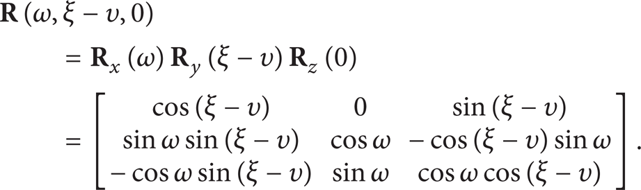
For convenience, the geometrical parameters of the tool heads are defined as oP i = R1, O′T i = R2, and B i P i = L(i = 1, 2, 3). According to the feature that the rotational axes of the discussed mechanisms are parallel to the x-axis of the global frame ℜ and coincident with the y′-axis of the mobile frame ℜ′, the description method of the RPY angles should be more reasonable for their orientation description. Under this method, the rotation matrix can be written as

As the description in Section 2, P1 and P3 are constrained within the o-yz plane. Therefore, the x-components of the point P1 and P3 should be zero; that is, P1 – x = P3 – x = 0. Then, we can get

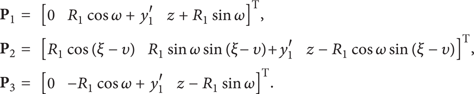
It is well known that the parasitic motions are the unwanted motions occurred in the constraint directions [13] and should be identified first in the kinematic analysis process. For both of the mechanisms shown in Figures 2(a) and 2(b), the limbs 1 and 3 are PRU kinematic chains. Therefore, the mobile platform can translate only in the plane (the o-yz plane) constituted by limbs 1 and 3, and the translational DoF along the x-axis is restricted by these two limbs. Then, there is no unwanted motion along the x-axis. Note that the translational DoF along the y-axis is restricted by the second limb, but the spherical joint in limb 3 of the 2PRU-1PRS mechanism (see Figure 2(a)) and the universal joint in limb 3 (see Figure 2(b)) of the 2PRU-1PUR mechanism make the unwanted motion along the y-axis occur when the tool head's orientation changes. So, only the parasitic motion along the y-axis exists, and it can be denoted by y0. And the coordinates of P i (i = 1, 2, 3) under the mobile frame ℜ′ can be represented by P1(0, R1, 0), P2(R1, 0, 0), and P3(0, – R1, 0). Multiplied by the matrix derived in (2), the coordinates of P i (i = 1, 2, 3) under the global frame ℜ can be generated. For an arbitrary position and orientation (ω, ξ, z), the coordinates of P i (i = 1, 2, 3) considering the parasitic motion can be expressed by

3.1. 2PRU-1PRS Mechanism
For the 2PRU-1PRS mechanism shown in Figure 2(a), its parasitic motion is expressed by y1 here and the constraints in the second limb (PRS limb) require that the y-component of P2 under the global frame ℜ should be zero; that is, y1 + R1sinωsinξ = 0. Therefore, we can get

Then, the coordinates of P i (i = 1, 2, 3) under the global frame ℜ can be rewritten as

The coordinates of B
i
(i = 1, 2, 3) under the global frame ℜ can be expressed by B1(0, R2, z11), B2(R2, 0, z12), and B3(0, – R2, z13). Under the constraint of

For the presented configuration of the mechanism in Figure 2(a), the sign “−” in (6) is taken here.
3.2. 2PRU-1PUR Mechanism
For the 2PRU-1PUR mechanism shown in Figure 2(b), the parasitic motion is denoted by y2. The sliders' positions under the global frame ℜ can be denoted by B1(0, R2, z21), B2(R2, 0, z22), and B3(0, – R2, z23). According to the constraints of the second limb (PUR limb), the directions of vectors

which leads to
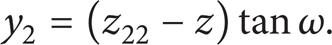
Considering the condition

where a = 1 + tan2ω,
Substituting (9) into (8), the parasitic motion of the 2PRU-1PUR mechanism can be rewritten as
Similarly, using the constraints


In (11) and (12), the sign “−” is taken. Then, the inverse solutions of the mechanism can be resolved by (9), (11), and (12).
On the basis of the analysis and derivation in Sections 3.1 and 3.2, the T&T angles [19] are used here to clearly reflect the orientation capability of the discussed tool heads. As shown in Figure 3, an arbitrary vector

Orientation description under the T&T angles.
In Figure 3, the vector

When this vector is used to represent the direction vector of the discussed tool head, it can also be expressed by the following equation:

Incorporating (13) and (14), the relationship between (ω, ξ) and (φ, θ) can be generated as

where ω,
4. Orientation Capability Analysis and Optimization
4.1. Normalization of the Geometric Parameters
For the mechanisms shown in Figures 2(a) and 2(b), they have similar structures and the parameter definitions are identical. In the optimization process, there are three geometric parameters to be normalized. Let

Parameter design space of the tool heads: (a) spatial view; (b) planar view.
The mapping functions of (s, t) and (l, r1, r2) can be derived as

4.2. Investigation of the Orientation Capability and Parasitic Motion
To investigate the orientation capability of the discussed mechanisms, the motion/force transmission performance is taken into consideration here. By taking Screw theory [21] as the mathematic foundation and using the performance-chart based design methodology (PCbSM) [20], the orientation capability investigation and optimal design process based on the already established Local Transmission Index (LTI) [22] are as follows.
The input twist screws of the three limbs can be expressed by

And the transmission wrench screws can be derived by

and the constraint wrench screws of the mobile platform can be expressed by


Assume that the output twist screws of the mobile platform can be denoted by

which can be uniquely identified by the following conditions

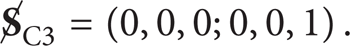
On this basis, the input transmission index (ITI) of each limb can be derived by

And, similarly, the output transmission index (OTI) of each limb can be derived by
Consequently, the local transmission index (LTI) evaluating the motion/force transmissibility of the discussed mechanism can be defined as

Based on the definition of local transmission index in (26), a good transmission workspace (GTW) under the description of (φ, θ) can be identified by the constraint of κ ≥ sin40°. In the GTW, there exists a maximal circular region ℑ defined by 0 ≤ φ ≤ 2π and 0 ≤ θ ≤ θmax. Then, the θmax is defined as the good transmission orientation capability (GTOC) of the discussed mechanism here and can be denoted by

To investigate the global motion/force transmission performance of the discussed mechanism over the circular region ℑ, a global transmission index (GTI) is defined as

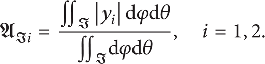
To investigate the parasitic motion distribution of the discussed mechanism over the circular region ℑ, a global average parasitic motion (GAPM) is defined as
According to the definitions given in (27) and (28), the distribution of GTOC and GTI can be plotted in the parameter design space generated in Figure 4(b). The GTOC distribution of the 2PRU-1PRS mechanism and that of 2PRU-1PUR mechanism are presented in Figures 5 and 6, respectively. From these figures, we can see that the GTOC of the 2PRU-1PRS mechanism is higher than that of the 2PRU-1PUR mechanism. Figures 7 and 8 show the corresponding distribution of GTIs of the two mechanisms. By comparison, a similar result can be derived and the GTI distribution of the 2PRU-1PRS mechanism is better.
Good transmission orientation capability of the 2PRU-1PRS mechanism.

Good transmission orientation capability of the 2PRU-1PUR mechanism.
Global transmission index of the 2PRU-1PRS mechanism.

Global transmission index of the 2PRU-1PUR mechanism.
Incorporating (4), (10), and (29), the GAPM atlases of the two mechanisms can be plotted in Figures 9 and 10. Obviously, the GAPM of the 2PRU-1PRS mechanism is much smaller than that of the 2PRU-1PRS mechanism.

Parasitic motion of the 2PRU-1PRS mechanism.

Parasitic motion of the 2PRU-1PUR mechanism.
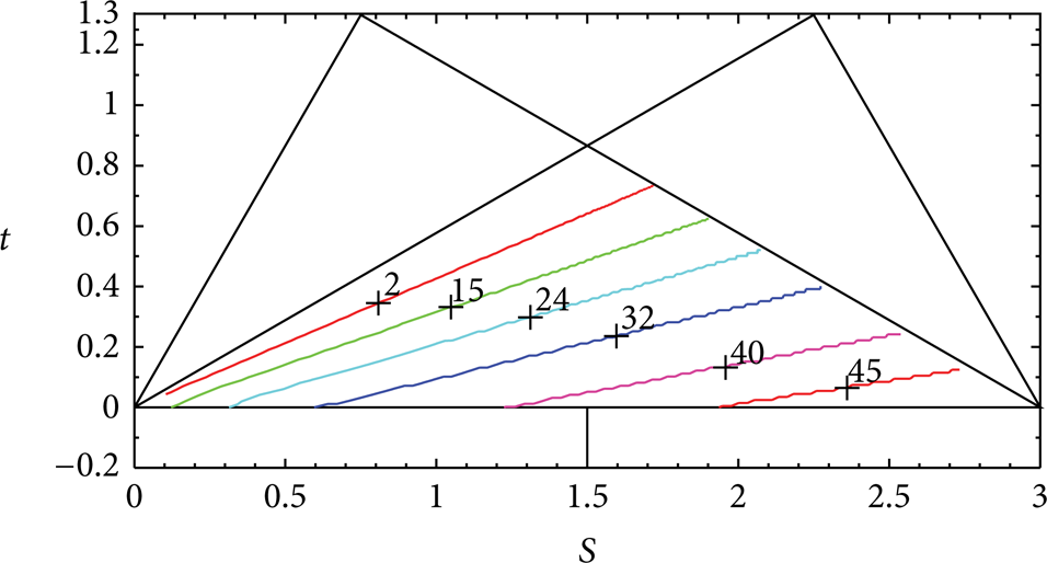
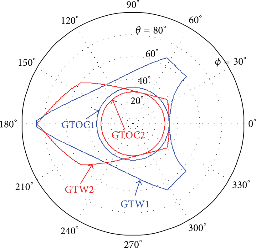
Based on the comparison results, it can be concluded that the performance of the 2PRU-1PRS mechanism is better, especially with respect to GTOC, GTI, and GAPM. Of note is that the GTOC is just a circular area in GTW. In order to investigate the distribution of GTW, three sets of normalized parameters as listed in Table 1 are taken as samples to carry out the comparison, and the specific values of GTOC, GTI, and GAPM are also included in this table. The corresponding GTW distribution atlases of the two mechanisms are presented in Figures 11, 12, and 13, in which GTOC1 and GTW1 are the corresponding GTOC and GTW boundaries of the 2PRU-1PRS mechanism, and, similarly, GTOC2 and GTW2 are those of the 2PRU-1PUR mechanism.
Performance comparison of the two mechanisms with different parameters.

Orientation capability comparison of the two mechanisms with parameters r1 = 0.75, and l = 1.25, r2 = 1.
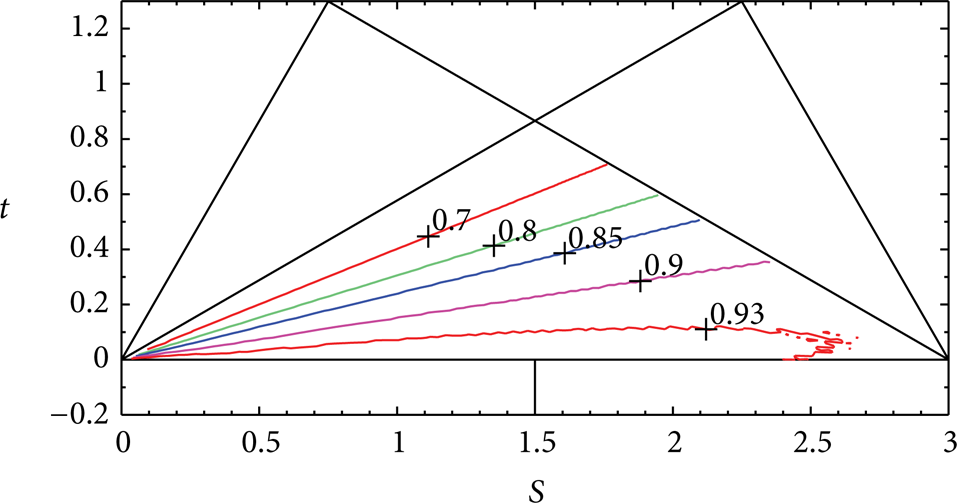
Orientation capability comparison of the two mechanisms with parameters r1 = 0.5, l = 1.5, r2 = 1.

Orientation capability comparison of the two mechanisms with parameters r1 = 0.2, l = 2.3, and r2 = 0.5.
From these atlases we can see that, the GTW of the 2PRU-1PRS mechanism is also better than that of the 2PRU-1PUR mechanism with the same parameters. Therefore, the 2PRU-1PRS mechanism will be the research focus in the following sections.
4.3. Optimization of the Orientation Capability
On the basis of the performance atlases generated in the previous section, the orientation capability optimization of the 2PRU-1PRS mechanism is carried out. By constraining WGTOC ≥ 40° and Ψℑ ≥ 0.92, an optimum region (the shaded area) can be identified as shown in Figure 14. Note that the parasitic motion of this mechanism is very small; therefore, the GAPM is not taken into consideration in the identification of the optimum region.

An optimum region of the 2PRU-1PRS mechanism.
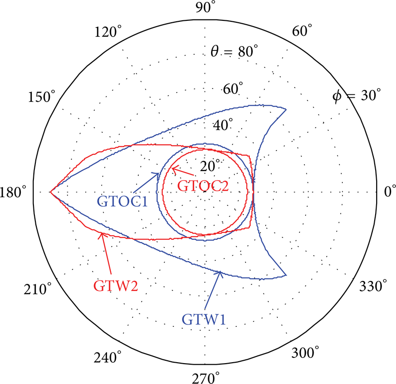
In the shaded area of Figure 14, a set of parameters is chosen as r1 = 0.4, l = 2, and r2 = 0.6. The corresponding values of the defined indices are WGTOC1 = 41.25°, Ψℑ1 = 0.93, and 𝔄ℑ1 = 0.0215. The distributions of GTW1 and GTOC1 are presented in Figure 15. For the convenience of comparison, the performance index values of the 2PRU-1PUR mechanism are obtained as WGTOC2 = 37.82°, Ψℑ2 = 0.91, and 𝔄ℑ2 = 0.4166. Similarly, the GTW2 and GTOC2 are also plotted in Figure 15. The parasitic motion distribution comparison of the two mechanisms with the same parameters is given in Figure 16. The advantages of the 2PRU-1PRS mechanism are distinct by the above comparison.

Orientation capability comparison of the two mechanisms with parameters r1 = 0.4, l = 2, and r2 = 0.6.
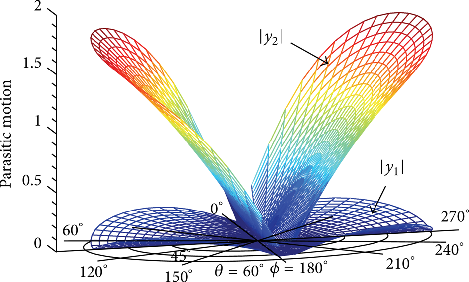
Parasitic motion comparison of the two mechanisms with parameters r1 = 0.4, l = 2, and r2 = 0.6.
For the blue atlas presented in Figure 15, the GTOC1 is much smaller than the GTW1 due to the restriction of boundary points when φ = 0°. The similar phenomena can also be observed in Figures 11, 12, and 13. After analysis, it can be found that the angle θ under the condition of φ = 0° is the output angle of the second limb. This means that the restriction of GTOC1 can be eliminated or decreased by introducing a deviation angle υ in the second limb. The kinematic scheme of the 2PRU-1PRS mechanism with a deviation angle is presented in Figure 17.

Kinematic scheme of the 2PRU-1PRS mechanism with deviation.
Considering the deviation angle υ of the second limb, the rotation matrix given in (2) should be rewritten as
Multiplied by the rotation matrix in (30), the coordinates of P2 can be expressed by
Similarly, the y-component of P i is restricted in the o-xz plane, and this leads to

Then, the coordinates of P i under the global frame ℜ can be rewritten as

The coordinates of B
i
under the global frame ℜ can be denoted by B1(0, R2, z1), B2(R2, 0, z2), and B3(0, – R2, z3). Under the constraint of

and the sign “−” is taken here.
Based on the already generated parameters r1 = 0.4, l = 2, and r2 = 0.6 and incorporating (27) and (34), the relationship between the deviation angle υ and the GTOC is derived and presented in Figure 18. From this figures, we can see that the GTOC achieves its maximum value (WGTOC ≈ 51.28°) when υ = 10°. Figure 19 presents the GTOC and GTW distribution comparison when υ = 10° (the pink atlas) and υ = 0° (the blue atlas). And Figure 20 shows the change of parasitic motion when υ = 10° (i.e.,

The relationship between GTOC and υ.
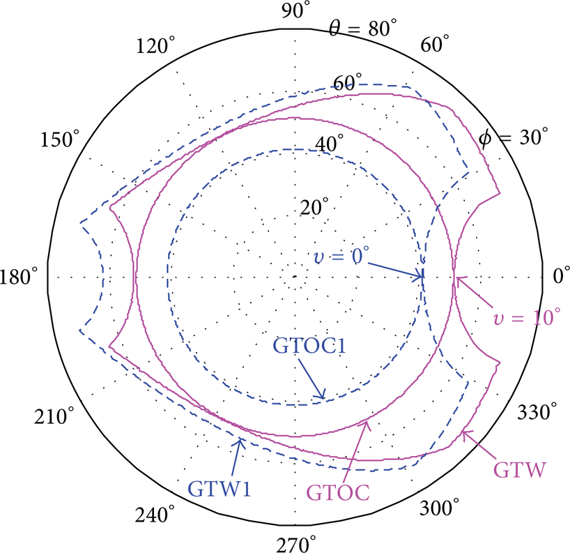
Comparison of orientation optimization effect.

Parasitic motions before and after the optimization of deviation υ.
In conclusion, the parameters of the mechanism given in Figure 17 are r1 = 0.4, l = 2, r2 = 0.6, and υ = 10°, and the orientation capability of more than 50° can be achieved (WGTOC ≈ 51.28°). Compared with the 3-PRS mechanism with the same parameters, the advantage in terms of parasitic motions is not distinct; that is, no great difference can be observed in Figure 21. But the orientation capability (WGTOC ≈ 51.28°) is obviously better than that of the 3-PRS mechanism (WGTOC = 43.5°) [14]. When used as a machining unit, the advantage of higher orientation capability can dramatically increase the machining flexibility and the consequent efficiency, which is of great value for practical application.

Parasitic motion comparison of the 2PRU-1PRS and 3-PRS.
5. Application and Prototype Development
The mechanism given in Figure 17 will be used to develop a five-axis hybrid machine tool, and the optimized parameters will be adopted. Of note is that the provided geometric parameters are normalized and the orientation capability of the mechanism is only related to the ratio of these parameters. In practical application, r1 = 0.4, l = 2, and r2 = 0.6 should be multiplied by a scale factor D to derive the actual parameters, and this factor D is decided by the specific application requirements.
The configuration of the five-axis hybrid machine tool to be developed is shown in Figure 22. In which, the mechanism given in Figure 17 is used as a tool head module to realize one translational DoF and two rotational DoFs. Incorporating two sliding tables with large translational capability, the five-axis configuration is established. Based on the work presented in this paper, the hybrid machine tool will be developed in the near future.

CAD model of a five-axis hybrid machine tool.
6. Conclusion
In the current paper, two novel articulated tool heads with parallel kinematics have been proposed and their architectures have been introduced in detail. Upon the proposed mechanisms, the analysis and comparison with respect to the orientation and parasitic motions have been carried out. Taking the motion/force transmission performance into consideration and using the local transmission index as the performance evaluation criterion, the orientation capability of the proposed mechanisms has been investigated and a preferred configuration with better performance has been selected. Based on the performance evaluation results, the dimensional synthesis using performance atlas method has been carried out and the optimized geometric parameters have been derived. In order to get higher orientation output capability, a geometric deviation parameter has been brought into the selected configuration. By optimizing this deviation parameter, the orientation output capability of more than fifty degrees has been achieved, which is a great merit for the machining application. On the basis of the comparison and optimization, the proposed mechanism and the optimized parameters have been used in the design and development of a five-axis hybrid machine tool.
Footnotes
Acknowledgments
This work was supported in part by the National Natural Science Foundation of China under Grants 51305222 and 51135008, National Basic Research Program (973 Program) of China (Grant no. 2013CB035400), and the China Postdoctoral Science Foundation under Grants 2013T60107.