
Abstract
The paper presents a method and a system for assessing the kinematic parameters of distant noncooperative objects. An experimental measuring system was developed using a long distance laser rangefinder, a GPS receiver, an electronic inclinometer, and a CCD camera mounted on a motorized pan-tilt unit. During the measurement process, the system first establishes its position and orientation in a global coordinate system. Particle filtering approach based on adaptive template matching is used to track a moving object of interest in the acquired digital image sequence. The tracking and rangefinder data is employed to determine in real time the relative position of the object, thus obtaining its 3D trajectory and velocity. To enable repetitive range measurements, the tracking data is also used to actuate the pan-tilt unit directing the rangefinder towards the object. Experiments are presented which demonstrate the performance of the system for characterization of movement of vehicles and people at kilometer-range distances.
1. Introduction
The characterization of the movement of different noncooperative objects has been the focus of studies in different fields. The development of modern computer vision systems that employ high performance cameras and advanced image processing algorithms has paved the way for new applications in surveillance, traffic monitoring, people tracking, and elsewhere. The advances and availability of various tracking solutions also enabled the study of human behavior in different environments [1, 2].
A commonly used approach is to utilize one or more cameras placed in convenient locations to observe the passing objects of interest [3, 4]. Then, by employing different image processing techniques, the moving objects are detected, discriminated from one another, and tracked through the image sequence. However, depending solely on visual information has certain shortcomings that become apparent especially when lighting is changed and also when dealing with different types of occlusions. Due to these limitations, visual tracking systems are often combined with laser scanners to improve the reliability [5, 6]. Laser scanners provide additional information at low computational complexity and are used to enhance the tracking performance. In certain cases, laser scanners provide sufficient information to perform people counting and tracking without the use of cameras [2, 7].
However, the majority of studies in the fields of people tracking and traffic monitoring perform the movement characterization at relatively small ranges since the measuring range is often limited by the employed laser scanners which are capable of measuring distances of only a few hundred meters. Also, in cases of commonly used single-row laser scanners, the applications are restricted to relatively flat terrain. This limits the applicability in both urban and nonurban environments.
In the presented work, we investigate the possibilities for real-time assessment of the kinematic parameters of noncooperative objects at kilometer-range distances. The term noncooperative refers to the fact that the objects of interest are not marked, prepared, or equipped in any way that would facilitate the measuring process. To achieve this functionality, we combine a long distance laser rangefinder with a custom visual tracking system. This enables the exploitation of efficient tracking algorithms to maintain the orientation of the laser rangefinder's optical axis towards the distant object. In this way, the repeated measurements of the object's relative position are performed. The presented approach yields the 3D velocity and trajectory information in a global coordinate system.
This paper is organized as follows. In Section 2, we describe the experimental system and our approach to visual tracking based on particle filtering and adaptive template matching. Section 3 presents the experimental work aimed at measuring vehicle and people kinematics in real time. Furthermore, the obtained results are discussed and compared to the reference measurements. Finally, in Section 4 we summarize the main achievements and expose key limitations of the developed experimental system and the employed methodology.
2. Experimental System
For characterization of kinematic parameters of distant objects, we have developed an experimental measuring system, which is composed of COTS (commercial of-the-shelf) components. It employs an eye-safe laser rangefinder with a measuring range of 50 m to 20 km, a high performance grayscale CCD camera with a 100 mm focal length lens, a GPS receiver/compass, an electronic inclinometer, and an inertially stabilized pan-tilt unit. The camera and the laser rangefinder are mounted on the pan-tilt unit, while the GPS receiver/compass and electronic inclinometer are attached to the platform base (Figure 1). The system is controlled by a personal computer with custom software.
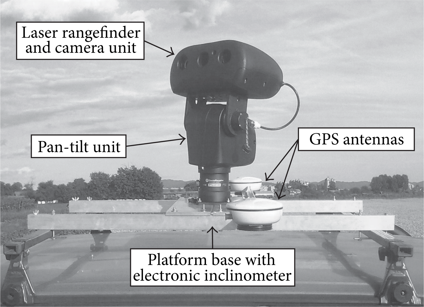
Experimental measuring system.
In comparison with a single-row laser scanner, the employed laser rangefinder is capable of measuring longer distances. On the other hand, its measuring frequency is significantly lower since it is designed to measure the distance to a single point, whereas the laser scanner measures the distances to multiple points in its field of view.
The experimental measuring system was initially designed for measuring the geographic location of distant stationary objects [8] and has been subsequently upgraded for measuring the kinematic parameters of moving objects. This was achieved with the integration of a high performance, thermoelectrically cooled CCD camera and appropriate image processing techniques.
During the measurement process, the GPS receiver is used to determine the position of the measuring system with the specified uncertainty of 0.6 m (95% confidence). Next, the relative position of the distant object is measured by the GPS compass, the electronic inclinometer, and the laser rangefinder. According to the manufacturer specification, the measurement uncertainties of the azimuth, elevation, and distance are ±0.3° (95% confidence), ±0.5° (95% confidence), and ±3 m (95% confidence), respectively. Using the acquired measurements, the position of the distant object is first determined in the WGS 84 Cartesian coordinate system and then transformed to the WGS 84 geodetic coordinate system utilizing an iterative method [8, 9].
For assessment of the distant object kinematics, the employed CCD camera acquires images at the resolution of 672 × 448 pixels. With the appropriate image processing algorithms, the location of the distant object in the image is determined. This information is then used as an additional measurement and also to actuate the pan-tilt unit in order to maintain the orientation of the laser rangefinder towards the distant object. With the 100 mm focal length lens, the horizontal field of view of the optical system is 2.48° or approximately 0.064 mrad/pixel. This angle is considerably smaller than the 1 mrad beam divergence of the laser rangefinder and thus allows a precise determination of the distant object position.
2.1. Visual Tracking
The task of visual object tracking is to determine the location of the object of interest in every frame of the image sequence. The approach to visual object tracking highly depends on the specifics of each individual application. We conducted a series of preliminary experiments on recorded image sequences of distant moving people and vehicles in order to test various possible approaches and determine a suitable one. We examined the options of relying on color histogram, movement, and intensity distribution information. Based on the results, we selected the adaptive template matching technique [10] as the basis for our method because this approach offers the possibility for at least partial elimination of the effects of changes in lighting and reflections, which often occur in outdoor environment. Additionally, the selected approach depends on the intensity distribution rather than on color information that is less reliable at long distances due to the atmospheric effects.
Our approach to the assessment of the kinematic parameters of distant objects is presented in Figure 2.
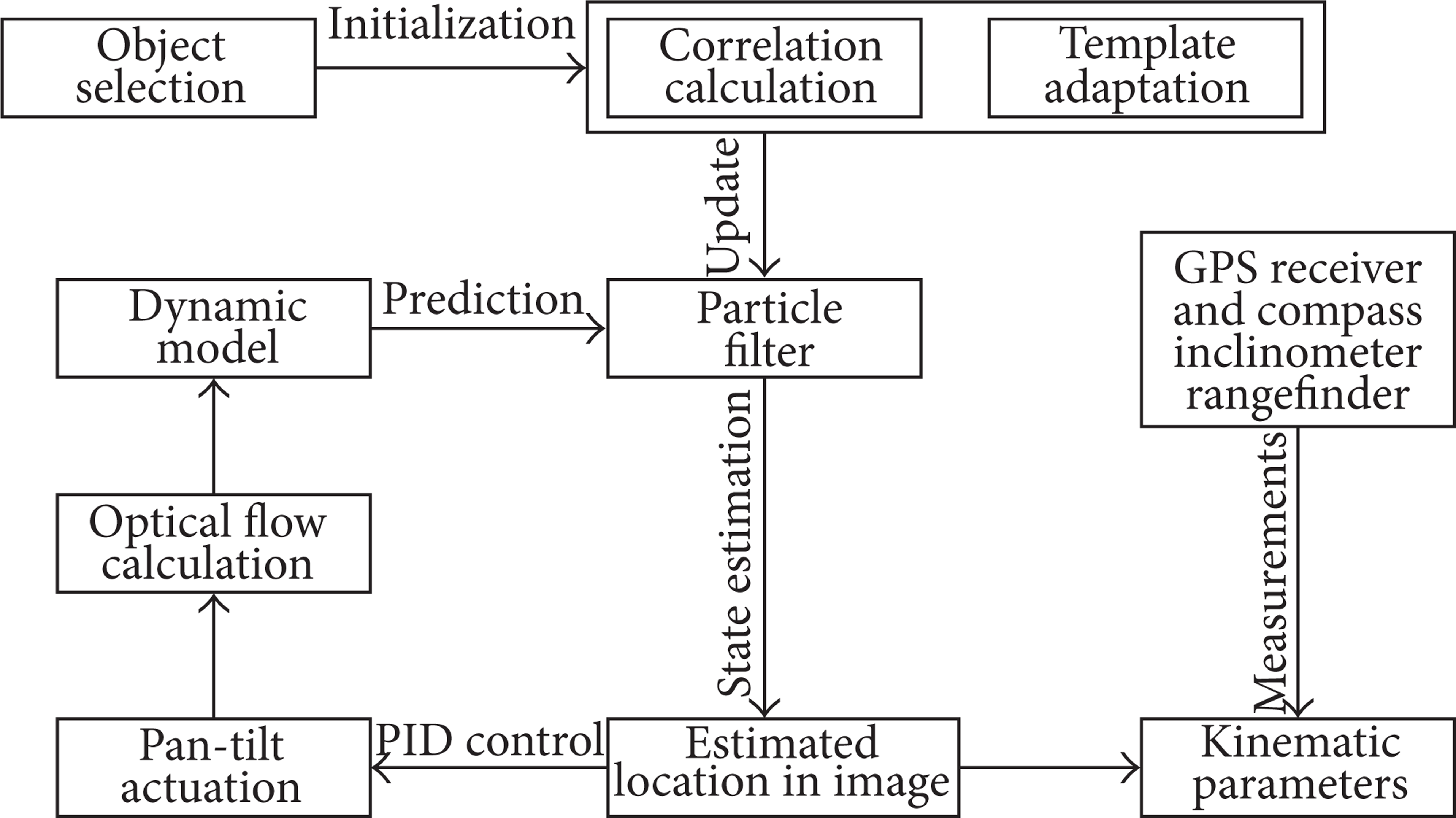
The schematic representation of the approach for assessing kinematic parameters of distant objects.
The tracking session is started by the operator who selects the object in the live video. A selection is performed with a rectangular region of 30 × 20 pixels which can be resized depending on the size of the tracked object. The selected region serves as an initial template for the template matching procedure. The similarity of a region in current image with the template is assessed with the normalized cross-correlation coefficient (1) which is calculated using a fast implementation in OpenCV library [11]. The utilized correlation approach is a well-established method for visual tracking or measuring displacements and deformations in image sequences [12, 13]:

where

In (1), M is the correlation metrics between the selected template T and the image region I at the location (x, y). In (2), w and h represent the width and height of the template T expressed in pixels.
However, the appearance of the object is expected to change over time due to changes in perspective, lighting conditions, occlusions, and so forth. To maintain the tracking ability, it is necessary to adapt the template according to the observed changes. We achieve this by evaluating the updated template [10] with a low-pass IIR filter with adaptive coefficients:

In (3), T k represents the current template, N k represents the region in the current image with the highest correlation coefficient Mmax, Tk + 1 represents the updated template, and α represents the adaptive coefficient that is proportional to Mmax.
The adaptive template matching procedure yields the location of the region in current image that is the most similar to the current template. By repeating the procedure through the entire image sequence, we obtain a track. Since every obtained location is a measurement with a certain measurement uncertainty, the track can contain abrupt changes in location or velocity which are not necessarily consistent with the dynamic properties of the tracked object. To address this issue, we introduce a dynamic object model and use it in a particle filtering approach to recursively estimate the state of the tracked object as the new measurements become available.
We utilize sets of particles (or samples) to approximate probability density functions that are used in Bayesian filtering as estimates of the system state (at time k) x
k
which is the location of the tracked object in the image and is represented by a set of weighted particles

SIR particle filter.
The probability distribution
The probability distribution
In the implementation of particle filtering, we use a version of SIR (sequential importance resampling) filter [15] which introduces the resampling step at every iteration to avoid the degeneration of the particle set. By resampling, the particles with small weights are removed, while the ones with high weights are multiplied to obtain an equally weighted particle set. In this way, the resampling step moves the particles towards the regions of high likelihood which are determined with the template matching procedure. Nevertheless, in the case of occlusion, the measurements based on template matching are irrelevant. For that reason, the resampling is not performed and the particles move according to the dynamic model, which increases the probability of restoring the track once the occlusion has passed. This is demonstrated in Figure 3 by an example of tracking a vehicle at a distance of about 1 km.

Vehicle tracking during occlusion.
In Figure 3, the tracking is performed with a set of 1000 particles that are represented as colored points. The color of each particle depends on its weight that is determined by the template matching procedure in the update step of the particle filter. The yellow circle represents the estimated location of the tracked vehicle and is calculated as the weighted average of the particle set.
During the process of tracking, the camera and the laser rangefinder move in order to maintain the orientation towards the moving object. To achieve this, we utilize a PID control algorithm where the estimated location of the distant object in the image is used to control the actuation of the pan-tilt unit. This movement introduces a substantial amount of vibration that decreases the image quality and limits the tracking ability of the system. In order to overcome this issue, we exploit the high sensitivity of the employed camera and reduce the exposure time to 1 ms. Another difficulty with the moving camera is that we need to properly characterize its movement in order to determine the kinematic parameters of the tracked object in a global coordinate system. This is achieved by the calculation of the optical flow of the background with an implementation of the Lucas-Kanade method [11].
3. Experiments
The experimental verification of the developed method and system was conducted in an open field to ensure adequate visibility of the tracked objects and proper operation of the GPS receiver. The assessment of the kinematic parameters was performed for moving people at distances of 500 m to 1 km and moving vehicles at distances of 1 km.
To control the measuring process we employed a personal computer with Intel Core 2 CPU and 1 GB memory. During the experiments, the camera was acquiring 17 frames per second at the resolution of 672 × 448 pixels while the laser rangefinder was performing distance measurement with the period of 6 s. The frame rate of the image acquisition was limited due to the recording of the acquired images to the hard disk of the system computer for the means of documentation. Without the recording, the achievable frame rate (limited by the camera) was 25 frames per second. The employed image processing algorithms alone (with the use of 1000 particles) are able to process 50 images per second.
3.1. Measurements of Vehicle Kinematics
To characterize the movement of a vehicle, we selected a road section that is positioned in lateral direction with respect to the position of the measuring system. This enables us to assess the performance of the visual measuring system and partially eliminate the effects of low measurement resolution and repetition rate of the employed laser rangefinder.
In the presented experiment the vehicle accelerated from 0 to 50 km/h, then started decelerating and finally disappeared behind obstacles. During the experiment, the vehicle was tracked from the distance of approximately 1 km by utilizing the presented measurement system. Since the outcomes of the visual tracking are expressed in pixels, we convert them to angles using the field of view per pixel which is calculated from the pixel size and the focal length of the camera lens.
The results of the optical flow measurements are displayed in Figure 4(a) as horizontal and vertical components of the camera angular velocities. By employing these measurements and the location of the tracked vehicle in the image, estimated by the particle filter, we obtain the angular velocities of the vehicle (Figure 4(b)).

(a) Angular velocities of the camera and (b) the tracked vehicle.
We notice that the vibrations of the camera manifested as fluctuations of angular velocity in Figure 4(a) are not transferred to the measured angular velocities of the vehicle (in Figure 4(b)). This means that the optical flow algorithm successfully compensates the mechanical vibrations that are produced by the actuators in the pan-tilt unit.
During the experiment, the distance to the moving vehicle was repeatedly measured by the laser rangefinder. Knowing of the distance enables the determination of the vehicle velocity with respect to the surroundings which is presented in Figure 5. To enable the evaluation of the characteristics of the remote measurement system we equipped the tracked vehicle with a high performance GPS receiver and a portable computer for recording the positions and velocities. The comparison of velocities acquired by the two set-ups shows good agreement. The calculated RMSE (root mean square error) before the total occlusion is 0.9 km/h. The time resolution of the velocity measurements, which is limited by the frame rate of the employed camera, is high enough to allow detection of shifting to higher gears during acceleration.

Velocity of the tracked vehicle.
3.2. Measurements of People Kinematics
To investigate the possibilities for characterizing the people movement with the developed measuring system, we performed several experiments with a person walking in different directions at distances above 500 m.
In Figure 6, we show a person that walks in various directions and slowly moves away from the measuring system. The parameter k below the frames represents the sequential frame number. We notice that the tracking is successful until the frame 1041. In later frames, the particles begin to move away from the tracked person, which is evident in frame 3291. This is caused by the template drift which is common in adaptive template matching and has been the topic of many studies [16, 17].
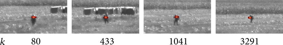
Selected frames acquired during tracking a moving person.
The obtained results clearly demonstrate the need to investigate the options for prevention of the template drift since it limits the ability to perform laser distance measurements after longer times. If the set of particles moves from the person, the laser rangefinder is unable to measure the distance to the person and measures the distance to the background instead.
With the present set-up we are able to track a moving person for several minutes before the template drift becomes too large to perform further measurements. An example of such tracking session is presented in Figure 7. Instead of the measured velocities, we show the obtained trajectory in horizontal plane (Figure 7(a)) and on a 3D map in Google Earth (Figure 7(b)). In the experiment, the tracked person carried a backpack with a high performance GPS receiver and a portable computer to record the positions and velocities. The GPS trajectory is also shown in Figures 7(a) and 7(b) to enable the evaluation of the performance of the developed measuring system.
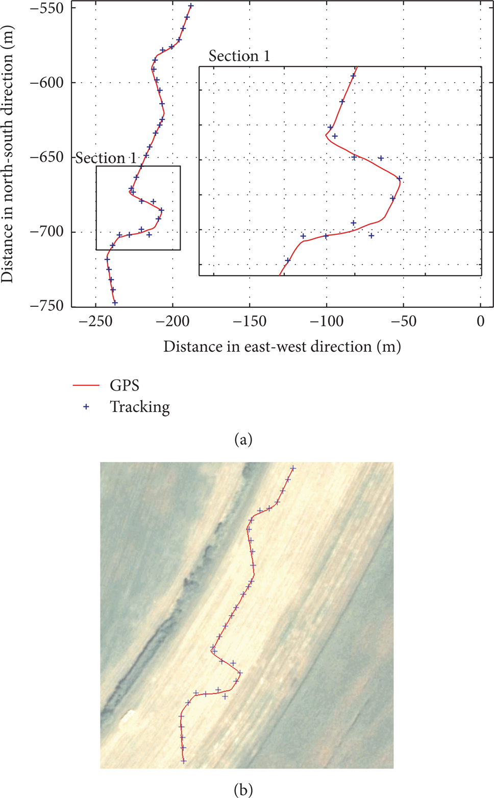
Trajectory of a moving person measured by means of the tracking system (symbols) and a GPS receiver (solid line) displayed in the horizontal plane (a) and on a 3D map (b).
The comparison of the trajectories in Figure 7(a) shows overall good agreement with few characteristic discrepancies, which become notable when the person moves in a tangential direction as can be seen in the enlarged section of the diagram. These differences are caused primarily by the distance measurement uncertainty which is about ±3 m (95% confidence level). Nevertheless, the calculated RMSE with respect to the reference GPS measurements is only 2.0 m.
Another set of experiments was performed at distances of approximately 1 km. The results showed that the tracking was successful only for a period of about 80 seconds. This is attributed to the effect of the template drift which causes the estimated location of the object in the image to move away from the actual location. The template drift eventually results in improper distance measurements which deteriorate the tracking performance. This issue is especially evident when tracking small objects at long distances.
4. Conclusion
The presented results demonstrate the possibility for characterization of the movement of various noncooperative objects at the distances up to 1 km, by acquiring their velocity and trajectory in real time. The developed experimental system integrates a laser rangefinder, a high performance CCD camera and appropriate image processing techniques to enable measurements over long distances in diverse terrains. The specific implementation determines the trajectory in a global coordinate system (WGS 84), allowing a straightforward display in a geographic information system. The key limitations of the current experimental set-up are low repetition rate and resolution of range measurements and template drift that occurs in longer tracking sessions.