
Abstract
The present study investigates the effects of thermal radiation on turbulent free triangular jets. Finite volume method is applied for solving mass, momentum, and energy equations simultaneously. Discrete ordinate method is used to determine radiation transfer equation (RTE). Results are presented in terms of velocity, kinetic energy, and its dissipation rate fields. Results show that thermal radiation speeds the development of velocity on the jet axis and enhances kinetic energy; therefore, when radiation is added to free jet its mixing power, due to extra kinetic energy, increases.
1. Introduction
Turbulent jets may be found in a plethora of engineering applications. Some examples are in the propulsion of aircrafts, the dispersion of pollutants, and the cooling of electronic packages. Jets can be classified as axial, radial, or tangential. Another classification based on the effect of the surrounding enclosure results in two types of jets, free jet and confined jet. In free jet, often termed as a jet in an infinite medium, there is negligible effect of the surrounding enclosure on its characteristics. In confined jet, the surrounding enclosure significantly affects the jet hydrodynamic characteristics [1]. In the literature, it has been shown that there can be significant differences between a jet in a confined or semiconfined enclosure and one in an infinite environment because of the recirculating flow entrained by the jet. Turbulent confined jets are encountered in several applications such as jet pumps, ejectors, and combustors.
Numerous studies have been undertaken to investigate the flow structure of free jets. Bhutada and Pangarkar [2] have predicted air entrainment rates for different area ratios for a fixed nozzle velocity and throat diameter. It was shown that an increase in the nozzle diameter increases the air entrainment rate. Ashforth-Frost and Jambunathan [3] have investigated the effect of the nozzle geometry and enclosure size on the potential core of a turbulent axisymmetric free air jet. They have investigated four nozzle tip conditions, namely, flat and fully developed velocity profiles for unconfined and confined nozzles. Miller et al. [4] simulated turbulent jets of circular and noncircular (elliptic, rectangular, and triangular) cross-sections with identical equivalent diameters. When compared with the circular jet, the noncircular jets were found to provide more efficient mixing, and therefore, an increase in spread and entrainment rates. Webster et al. [5] have investigated water jets and have reported excellent velocity agreement between their measurements and previous measurements. Singh et al. [6] have investigated the entrainment characteristics of confined and semiconfined circular and noncircular air jets experimentally. They have investigated nozzles of different shapes having equal flow cross-sectional area to study the noncircular jets. Balamurugan et al. [7] have carried out experimental investigations on ejectors employing gas (air) as a motive fluid and liquid (water) as the entrained fluid. Biswas and Mitra [8] studied the momentum transfer in horizontal multijet liquid gas reactors.
As aforementioned no studies have been conducted referencing the effects of surrounding thermal radiation on confined turbulent free jets. Therefore, the present work was carried out to find out the effects of radiation on the mentioned jets hydrodynamic characteristics. This article is in essence some parts of our ongoing studies [9].
2. Numerical Simulation
2.1. Computational Domain and Boundary Conditions
This section provides a brief description of the computational details as they were applied, in order to obtain a convergent solution of this flow. The free jet has been modeled as a three-dimensional block where all surfaces are defined as no slip wall boundaries. The walls are assumed to emit and reflect isotropically with constant wall emissivity. The wall temperature is constant and equal to 700 K. Velocity inlet with the geometry of triangle is placed on one surface of the block (YZ, X = 0). The fluid of the domain is stagnant air of atmospheric pressure and the inlet jet velocity of the air is 100 m/s in x direction while its turbulent intensity is 5%. The hydraulic diameter of the inlet is 10.046 mm and its geometry is equilateral triangle with all sides 17.4 mm. The dimension of the plate that the velocity inlet is placed on is 40 cm*40 cm (Figure 1).

Nozzle cross-section at plane YZ (X = 0).
2.2. CFD Modeling Strategy, Turbulence Model, and Numerical Details
To date the k-∊ model is the most widely and validated turbulence model. The generally chosen turbulence models for free jets are various versions of two-equation models like k-∊ model. Several versions of the k-∊ model have been proposed by Yakhot et al. [10]. They developed a more popular version of k-∊ model called k-∊ RNG. It has the same form as the standard model; however, the model constants are derived analytically from a mathematical method referred to as renormalization group theory. In addition, a second term also appears in the ∊ equation. In comparison with the standard k-∊, the k-∊ RNG turbulence model introduces smaller coefficients in the k-∊ equations. These reduced values mean that the decay of the turbulent dissipation in the ∊ equation is also reduced. This leads to higher values of ∊, and subsequently lower values of k and μ t . Therefore, it is expected that the k-∊ RNG model gives better results in the regions of the flow where the mean strain rates are high. The performance of the k-∊ RNG model of turbulence has been investigated by Knowles and Saddington [11], Gordeev et al. [12], Sharif and Mothe [13], Fernández et al. [14], Chen [15], Liakos et al. [16, 17] and Sharif and Mothe [18] in jet flows and all confirmed that the k-∊ RNG model can be successfully used to model this type of flows. The k-∊ RNG model is numerically robust and faster than the triple transport model and has minimum turn-over time requirements for the calculations [17]. Thus the k-∊ RNG turbulence model is used for modeling the turbulent behavior of the flow.
The second-order upwind discretization scheme is applied for the momentum, turbulent kinetic energy, and turbulent energy dissipation rate. The procedure used for the calculation of the flow field is the SIMPLEST algorithm which stands for semi-implicit method for pressure-linked equations [19, 20]. Discrete direction method for RTE has been applied. Steady state simulations are carried out and the solution is iterated until convergence is achieved, such that the residue for each equation fell below 10−4. All the equations have been solved with finite volume method.
2.3. Governing Equations
2.3.1. Basic Equations
The governing equations are the continuity, momentum, and energy equations. The following assumptions are considered for simulation of the flow: steady state, constant fluid properties, incompressibility, Newtonian fluid, and no natural convection:

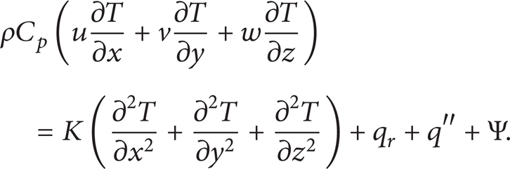
Because two terms Ψ, q″ in (2) are too small, they have been neglected in calculations.
2.3.2. Radiation Transfer Equations (RTE)
In this section the radiation term in energy balance equation (2) is investigated. Consider a finite volume with the thickness of ds. iλ′(s) enters and iλ′(s + ds) leaves the volume, respectively. The changes of radiative intensity were defined as follows and named by RTE:
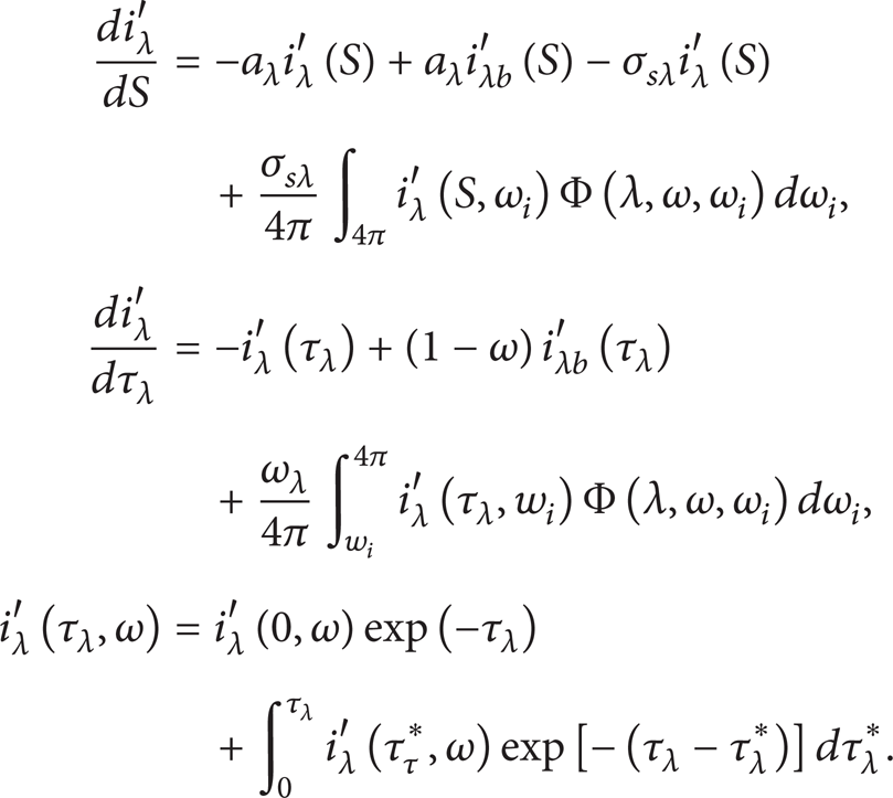
According to above equations the magnitude of the heat flux transmits to the assuming element (ds) is calculated with following relation that θ is the angle between direction of heat flux and surface:

And transmitted radiative flux shown in (2) is given by

2.3.3. Grid Generation
An acceptable grid distribution is one in which grids are focused on important regions of domain. Regions surrounding the centerline of the axial are of the most importance. Therefore, the densest grid covers these areas. Beyond the inlet region, a geometrically expanding grid is used with an expansion factor of 1.6 in both y and z directions and 1.3 in x direction. Employed meshes are quadrilateral.
According to the chosen turbulent model and boundary conditions, we carried out grid tests at U o = 100 m/s. Four kinds of grid distributions were employed with 40000, 80000, 120000, and 160000 nodes in the region and velocity distribution on the jet axis was plotted to compare their accuracy. The 120000 and 160000 grids did not produce any noticeable changes and then agreed with each other. The distributed grid with 120000 nodes may be considered as fine enough to provide acceptable, grid independent solutions and can be used throughout the rest of the calculations in this paper. For RTE solution the same meshes are used and creating new meshes is unnecessary.
3. Results and Discussion
3.1. Validation
It is necessary to validate the predicted values of the numerical simulations employed. In the present work, results are compared with parameters available from experimental studies which have been done at the University of Tabriz [21]. Computations were performed on a test case of a confined horizontally impinging jet on a flat plate. The properties of the nozzle exit were the same as our study case. The geometry of the nozzle was equilateral triangle with all sides being 17.4 mm (D h = 10.046 mm), the velocity of the inlet air jet was 100 m/s in x direction with turbulent intensity of 5%, and the domain fluid was stagnant air of atmospheric pressure. The dimension of the plate that velocity inlet was placed on was 40 × 40 cm2. Pressure at the stagnation point and the nozzle distance to the plate were, respectively, P s = 1672 Pa and 16 cm.
Figure 2 compares the predicted values of normalized pressure profiles as a function of vertical distance in the impinging plane. It can be seen that there is a good agreement between the CFD predictions and experimental datasets.
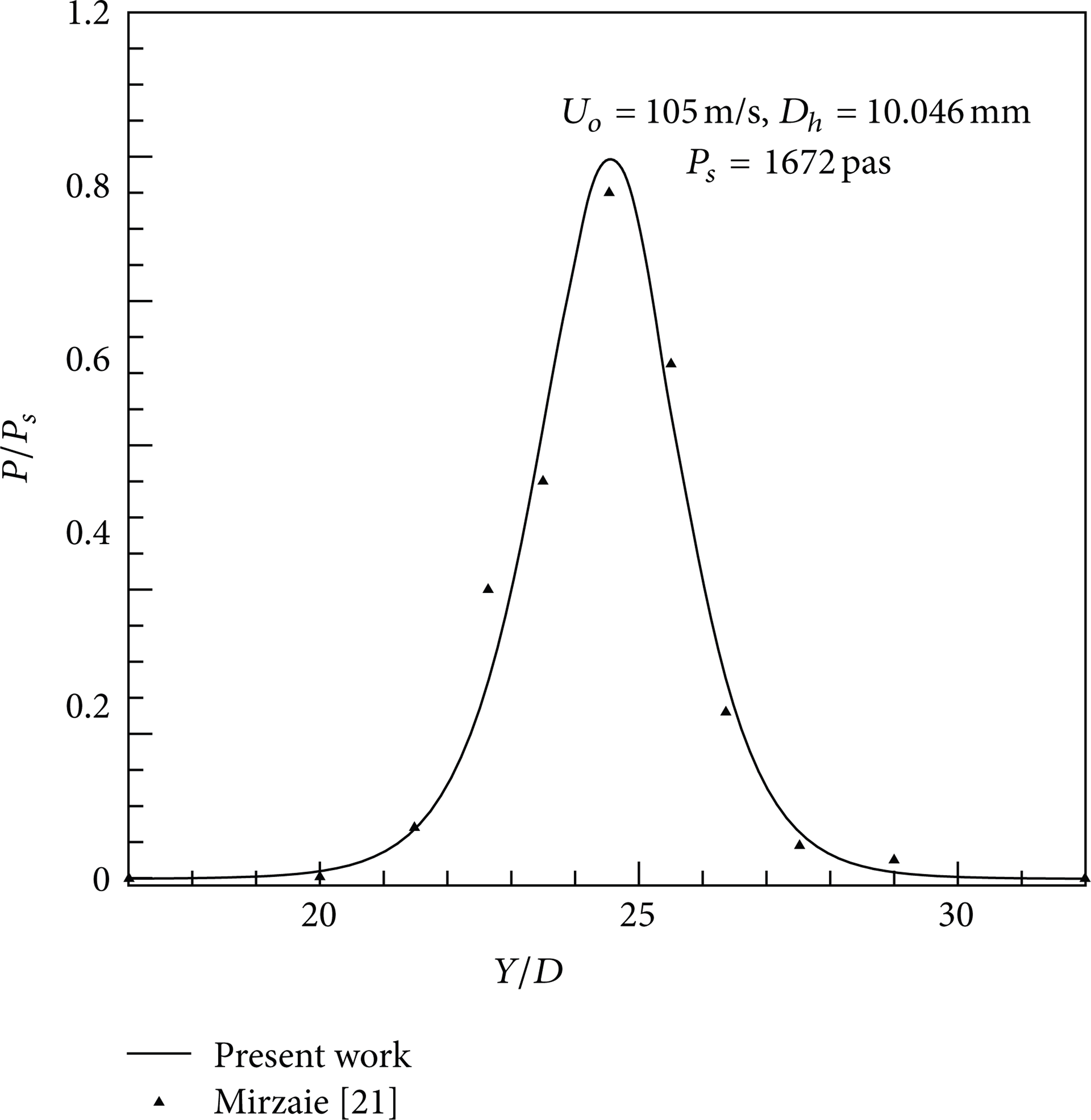
Comparison of predicted pressure distribution on wall jet with the previous literature.
3.2. Results of Numerical Simulation
We investigated the properties of free jets without radiation. The velocity of the jet on its axis (U o ) decreases so much that it reaches to the stagnant ambient fluid's velocity.
Velocity is constant in potential core region (equal to the nozzle exit velocity U o ) which is 100 m/s here. The potential core extends from the nozzle and is the central portion of the flow in which the velocity remains constant and almost equal to the nozzle velocity. It is formed as a result of turbulent mixing which originates near the nozzle tip. After this region, decay portion starts. In this region jet spreads radially entraining surrounding fluid, and the axial velocity decreases along the jet axis. Entrainment causes the potential core to disappear.
Figure 3 shows the pressure distribution on the jet axis. It is evident that the pressure is constant and proves continuous which is in agreement with the findings of Abramovich [22]. As shown by numerous experiments, one of the fundamental properties of a jet of this kind is the fact that the static pressure is constant throughout the flow, as a result of which the velocity in the potential core of the jet remains constant. The “eating up” of the jet beyond the initial area shows up both in its widening and in variation of the velocity along its axis [22].
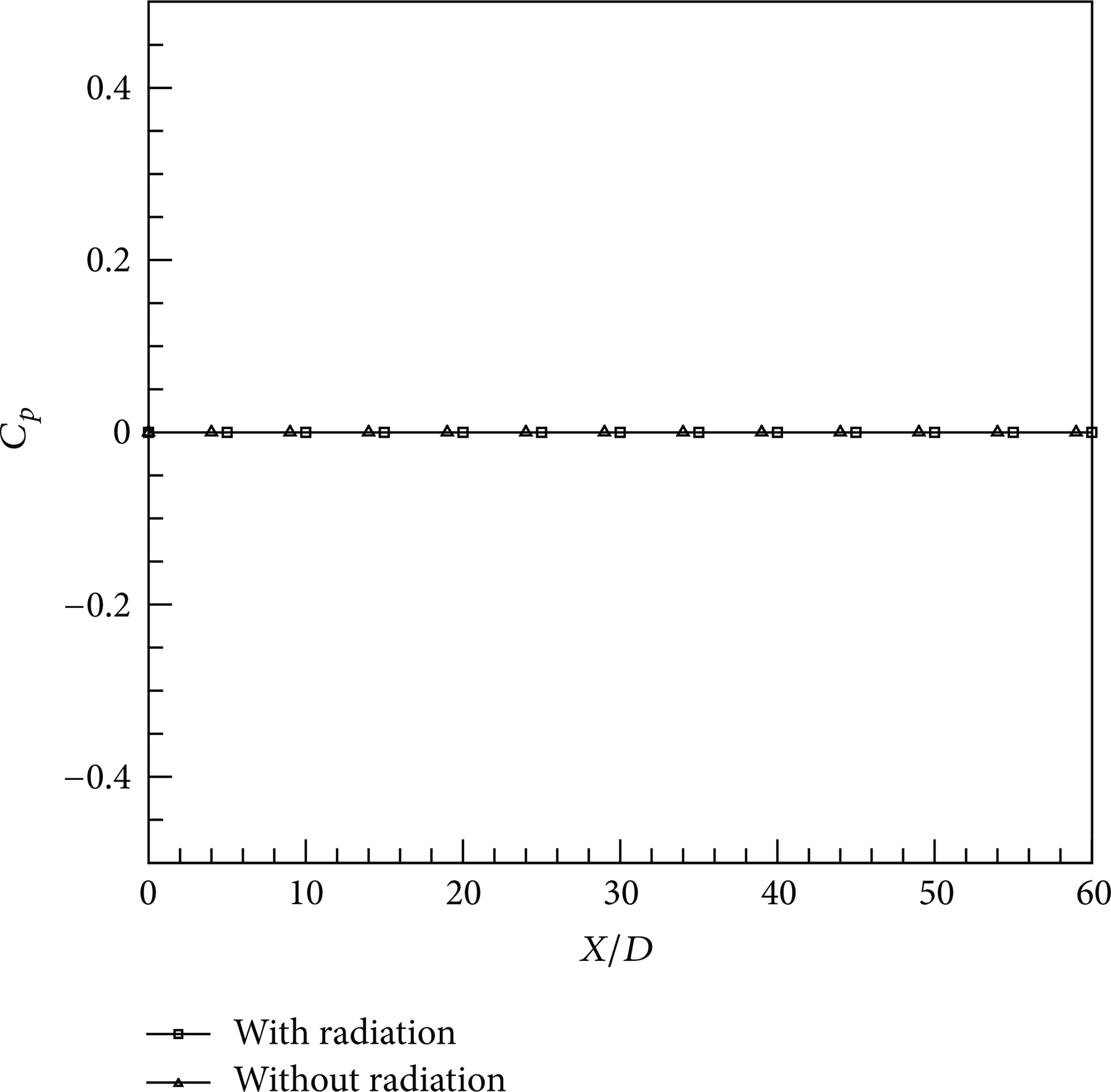
Pressure distribution on the jet axis.
In Figure 3, C p is the pressure coefficient and is defined as follows:

(P is the pressure on the jet axis and U o is velocity of the nozzle exit).
In Figure 4, the velocity contour on the vertical plane crossing the jet axis has been revealed. The potential core is seen obviously. In the decay portion or the region after potential core turbulence, due to the velocity gradient, shear is generated which leads to the generation of turbulence. Turbulent eddies cause the entrainment of the surrounding fluid into the jet flow. Hence the width of the mixing zone increases with downstream distance, after the potential core region [1]. In any section of the jet, the velocity has a maximum value which is located on the jet axis. When marching forward, it decreases and tends to zero while at the same time widening along its axis (Figure 5).

Velocity contour on the vertical plane crossing the jet axis (XZ plane).

Velocity distribution at different sections of the free triangular jet with thermal radiation effect.
When radiation from the boundaries has been added to the flow field through walls, the velocity magnitudes in any cross-section of the jet flow have been increased. Approximately there is 5–7% difference in the velocity magnitude between jet flows affected by radiation and without radiation. So thermal radiation speeds the development of velocity in free jet flows, which can be an interesting result (Figure 6).
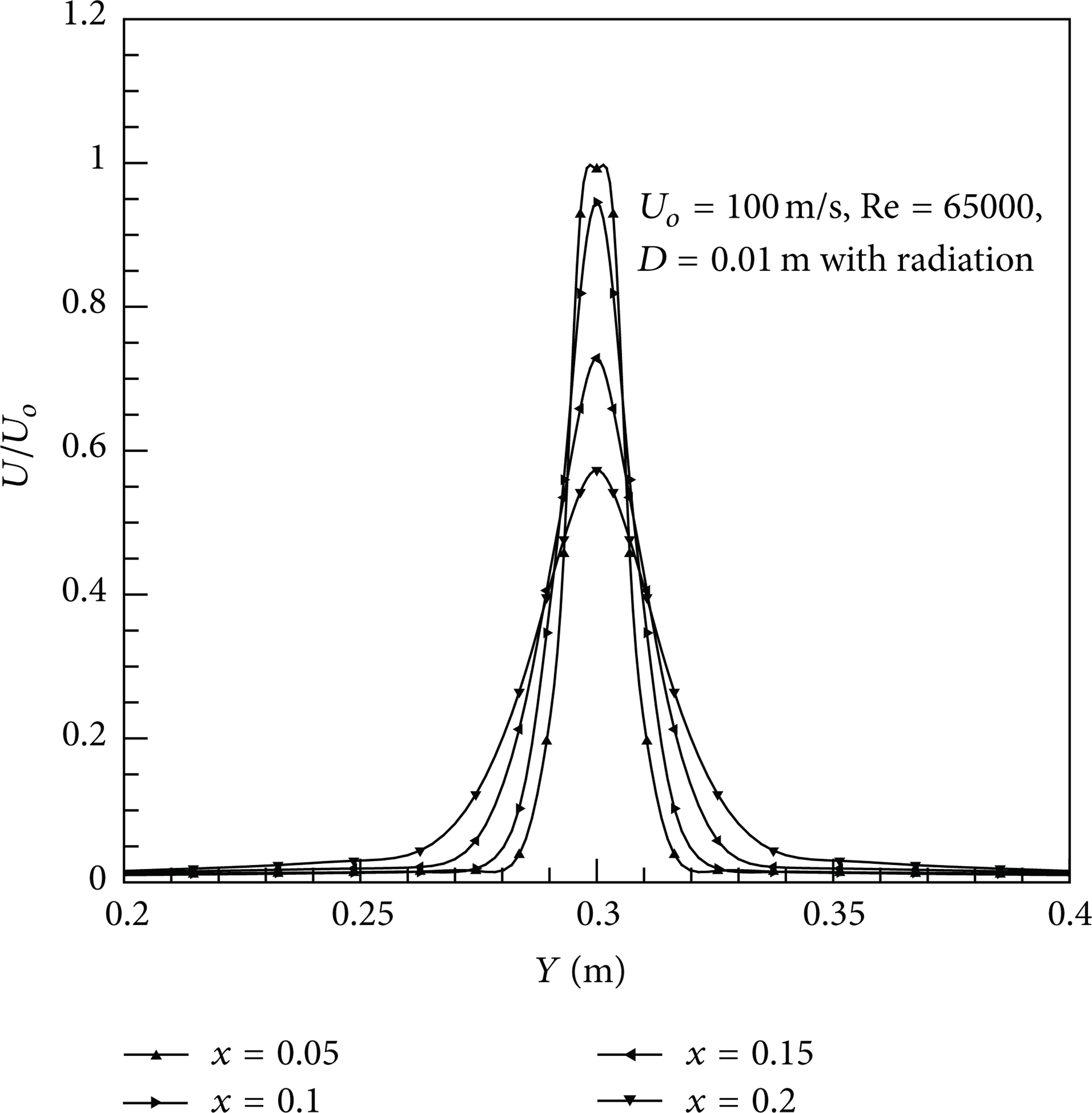
Velocity distribution at different sections of the free triangular jet with thermal radiation effect.
Figure 7 compares the axial velocity in free jets with and without thermal radiation effect. As shown, potential core in free jet when having thermal radiation effect is greater than free jet having no radiation effect. So the radiation case free jet preserves its momentum more than simple case and this is very useful in the applications where we need more dominance of the jet like combustion chambers. When having thermal radiation effect, if we plot the pressure distribution on the jet axis, we see that there is no difference between free jets having radiation and no radiation which is another interesting result (Figure 3).

Axial velocity in free jets with and without thermal radiation effect.
Figures 8 and 9 compare kinetic energy and its dissipation rate on the axis of two cases. In the potential core region because of the negligible velocity gradients, kinetic energy is approximately constant. However, in the decay portion because of strong gradients due to rigorous turbulence created by the velocity differences between jet fluid and stagnation ambient fluid, a sudden increase of k is observed. In fact, shear layers are the main reason of great turbulence in this region. As aforementioned, obviously, the radiation thermal effect increases the kinetic energy for free jets.

Kinetic energy on the jet axis of free jets when having thermal radiation effect and no radiation.

Kinetic energy dissipation on the jet axis of free jets when having thermal radiation effect and no radiation.
An important result from the above discussions could arise. In the applications like cooling of turbine blades, confined jets with thermal radiation effect would be more useful. Because in cooling processes, great mixing effect and more dominance in needed. In jets affected by thermal radiation, due to strong turbulence, which are created more than jets without radiation effect, strong mixing effect occurs.
4. Conclusion
In the present study effects of thermal radiation on turbulent jet flow with triangular cross-section were investigated numerically. By using finite volume and discrete ordinate methods, basic equations were solved.
Results show that thermal radiation speeds the development of velocity on the jet axis and enhances kinetic energy. When radiation is added to free jet, its mixing power, due to its extra kinetic energy, increases.