
Abstract
This paper describes the development of a compact and lightweight joint torque sensor for space manipulators. Space manipulators with torque sensors can not only apply force control approach to more precise and more dexterous space missions, but also monitor the occurrence of unpredicted events as accidental impacts with objects they have to manipulate. At present, most of the compact torque sensors, designed without consideration of space environment, cannot be directly used in space applications. In this paper, we propose a compact and lightweight design for the joint torque sensor based on strain gauge, for the reason of good physical, chemical, and mechanical stabilities under high temperature environment. In addition, to reduce the interferences by axial forces generated by assembling condition and joint motors, the structural optimization for the sensing element is carried out. The proposed design is simulated by FEM software ANSYS, and it shows successful measurements of the torque with a load capacity of 10 Nm, which is sufficient for the torque generated in robot joints. The effect of axial loading is also analyzed by ANSYS. The designed sensor is manufactured by duralumin alloy. The calibration for the sensor is carried out, and several experiments are conducted to ensure its feasibility with the space manipulator.
1. Introduction
With the rapid development of space technology, the number of the human exploratory activities in space has constantly increased. Besides handling and assembling of large payloads, more precise and more dexterous space missions such as on-orbit maintainability and on-orbit capture appear in space [1–4]. These space missions promote the development of high performance space manipulator systems, which can move as dexterous as the arm of a man [5, 6]. For the successfully accomplishing tasks of these manipulators, it is essential to calculate the torque at each joint of the manipulator. Space manipulators with torque sensors can be not only applied force control approach to more precise and more dexterous space missions such as on-orbit maintainability and on-orbit capture appeared in space, but also monitor the occurrence of unpredicted events as accidental impacts with objects they have to manipulate, which may affect the reliability and safety of the manipulator and lead space missions to failures. The development of torque sensor for robotic system has been of great interest for decades [7–10], as the commercially available torque sensors are expensive, big, and need extra space in joints. In addition, owing to difficulty to customize commercially available sensors, considerable modifications of joints and links in manipulators are usually needed for assembling purpose. Thus, a variety of torque sensors were designed and developed for robotics systems with acceptable performance by different researchers [11–14].
Ktena et al. [11] designed a magnetostrictive sensor made of NiFe thin film electrodeposited on a cylindrical nonmagnetic 316 L stainless steel rod. They succeeded in developing a sensor with low cost and wide sensor range of 150 Nm. However, this sensor is more complex and appropriate for applications, where accuracy of measurement is not very important.
Yang et al. [12] presented a micro six-axis force sensor based on double layer E-type membrane. The size of the proposed sensor is considerably small; however, the moment/force detecting capability is limited to few micro-Newton meters.
Albu-Schäffer et al. [13] proposed compact design torque sensors for implementation of local impedance control of the lightweight robots (LWRs), which are developed at the Institute of Robotics and Mechatronics of the German Aerospace Center. This kind of sensor, based on strain gauge and used a low-pass filtering at 600 Hz, is capable of detecting 100 Nm load with a sensor error of 0.5%. However, on further experimental research, it was found that the axial forces generated by assembling condition and joint motors can easily affect zero drift characteristics, with hysteresis error varying in large range.
Shams et al. [14] developed a compact, lightweight, and monolithic torque sensor for robots with increased range. This sensor uses the optical technique to measure the torque, which is immune to electromagnetic interference and lightweight, and also requires simple electronics. The thickness of sensor is reduced up to 11 mm without reducing the range of the sensor, that is, 40 Nm. However, the sensing element, that is, photo-interrupter, is easily affected by space environment and is not appropriate for space applications, as the output optical power changes greatly along with ambient temperature varying in large range; furthermore, neutron radiation and r-ray irradiation may lead to aging or permanent damage in optical material.
Most of the compact torque sensors, designed without consideration of space environment, cannot directly used in space applications. At the same time, for a good torque sensor, it is essential to withstand varying axial forces exerted by assembling condition or the robot's body. In addition, torque sensors used in robot joints, placed between the output of speed reducer and the link, can increase the flexibility of the robot joint along with stiffness reducing of the sensor, that is, reduce the control precision and robust stability. So, it is understood that the torque sensor for space manipulators must be able to bear the interference from axial forces and have a high radial stiffness with sufficient resolution and accuracy and a good stability in harsh environment for a long time operation. Otherwise, it may lead to abortive space missions due to torque sensor failure.
In this paper, we propose a new compact and lightweight design of joint torque sensor for a load up to 5 Nm. The dimension of the torque is selected by considering the joint size of the space manipulator system (SMS) [15]. Strain gauge technique is used to detect the angular displacement. To reduce the interferences by axial forces, the structural optimization for the sensing element is carried out. As ambient temperature varying in large range in space, strain gauge temperature effects and temperature compensation for the sensor are considered. The designed torque sensor is compact and lightweight. Simulation was done by finite element method (FEM) software ANSYS, and the sensor was manufactured and calibrated. Several experiments (linearity, hysteresis, resolution, and repeatability) were conducted to ensure its feasibility with the space manipulator system.
This paper begins with a brief explanation of the torque sensor components, which follows the detail idea of using strain gauge approach to detect the angular displacement for SMS then discusses the concept design of flexure. Section 3 contains simulations of designed flexure using FEM software. Next section comprises of experiments and results of manufactured sensor. In the end, advantages and outcomes of the designed sensor is discussed, and future work is proposed.
2. The Sensor System
The proposed sensor system can be divided into two main parts. First part consists of the sensing element, that is, strain gauges. The second part is the flexure. Other parts of the sensor are sensor electronics. The strain gauges are appended on the flexure in a way that it can detect the slightest deformation of the flexure. A C program based on a field programmable gate array (FPGA) platform [15] is also developed to sample the data of the torque sensor.
2.1. The Strain Gauges
In recent years, a variety of techniques as optical techniques, magnetic techniques, mechanical oscillator techniques, and surface acoustic wave (SAW) techniques are being developed by different researchers to detect many different physical parameters [11, 14, 16–23], including displacement either linear or angular force and torque. Increased research in the field of torque sensing based on these techniques is due to its compact size, lightweight and simple electronics. However, application of these techniques is limited for intense radiation and large temperature variations (−200°C ∼ + 200°C) in space. On the other side, strain gauge technique, the most commonly used technique for torque sensors within the past decades [24–28], is increasingly applied for stress measurement under high temperature environment these years. This makes strain gauge technique a good choice for the torque sensing as we need a compact, lightweight, and reliable joint torque sensor for space applications. Therefore, in this research, the high temperature strain gauge was selected to be used as sensing element in the design torque cell.
The available high temperature strain gauges, whose maximum operating temperature is up to 250°C, are commonly used for structural stress measurement. Gauge selection for space applications mainly needs to meet the following points.
Good physical/chemical stability in the whole working temperature range.
Good mechanical stability in the whole working temperature range, that is, little gage factor variation with temperature.
Strain gauges with self-temperature compensation and high compensating range.
High and stable insulation resistance in the whole working temperature range.
High fatigue life and low thermal hysteresis.
Typical high temperature foil strain gauges with self-temperature compensation are listed in Table 1. Table 1 shows that almost all of strain-sensitive alloy of high temperature foil strain gauges are constantan (A-alloy) and modified Karma (K-alloy). For best self-temperature compensation effect, A-alloy and K-alloy can alter temperature coefficient of resistance to match the linear expansion coefficient of the designed flexure by changing alloy composition and controlling temperature and time of heat treatment. Typical thermal output variation with temperature for self-temperature-compensated constantan (A-alloy) and modified Karma (K-alloy) strain gages is shown in Figure 1.
High temperature foil strain gauges with self-temperature compensation.

High temperature epoxy-phenolic resin system reinforced with glass fibers.

Typical thermal output variation with temperature for self-temperature-compensated constantan (A-alloy) and modified Karma (K-alloy) strain gages.
As shown in Figure 1, A-alloy strain gages have excellent self-temperature-compensated characteristics in normal temperature. But thermal output of A-alloy strain gages changes greatly with temperature variation −50°C ∼ + 250°C, making complicated temperature compensation. On the other side, the thermal output variation of strain gauges made by K-alloy is relatively smooth in the whole working temperature range. This makes K-alloy strain gauges easy to determine temperature compensation point (TCP) and achieve better compensation effects compared with A-alloy strain gauges.
Gauge factors also change with temperature. As shown in Figure 2, gauge factors of A-alloy and K-alloy change with high linearity as the temperature rises, but the gauge factor variation of K-alloy has an opposite tendency with A-alloy. Previous studies have shown that elastic modulus (E) of the material for designed flexure decreases as the temperature rises [29]. Thus, the sensor output rises under rated load, that is, causing determinate error. And the gage factor increase of A-alloy strain gauges, as the temperature rises, can further increase this error. On the other side, K-alloy strain gauges can just compensate the impact of the decrease of elastic modulus. This makes K-alloy a better choice for high temperature strain measurement. Therefore, in this research the WK-series strain gauges were selected to be used as a sensing element in the design torque cell.
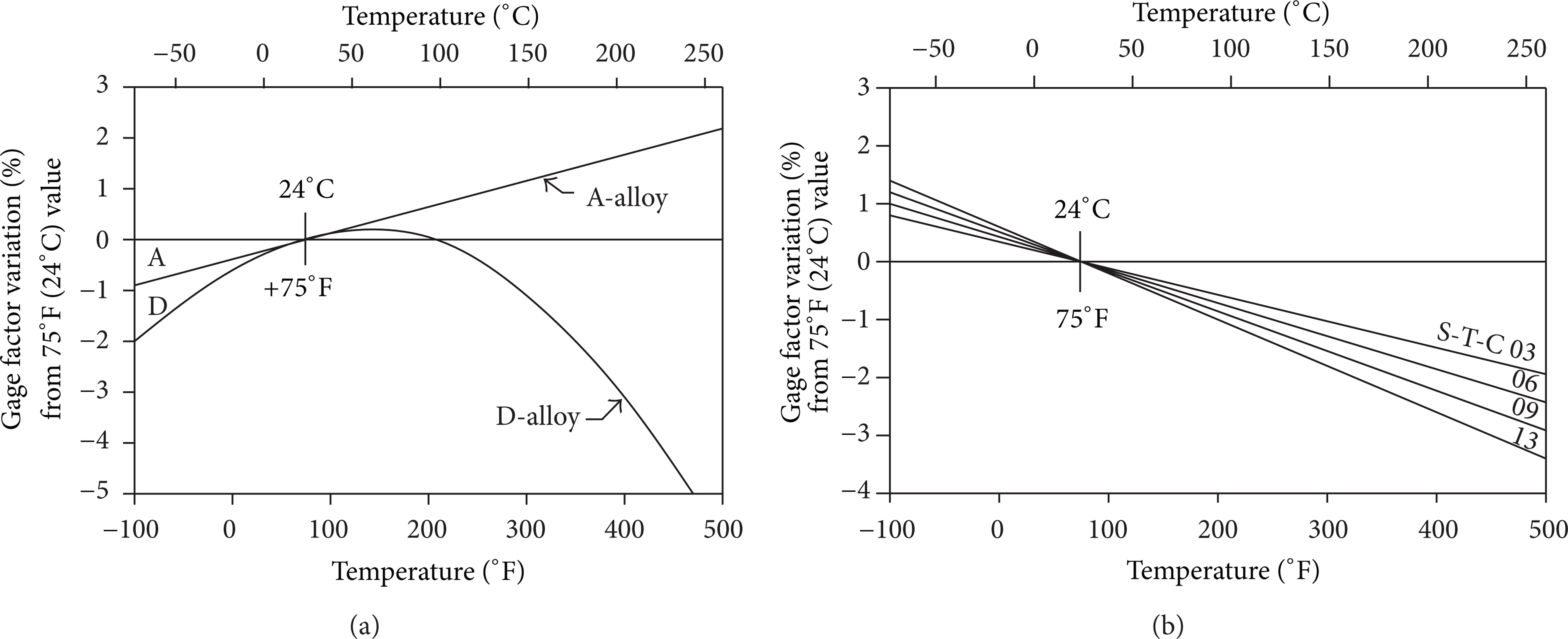
(a) Gage factor variation with temperature for constantan (A-alloy) and isoelastic (D-alloy) strain gages. (b) Variation of K-alloy gage factor with temperature and S-T-C number.
WK-series gages are fully encapsulated K-alloy, equipped with integral high-endurance beryllium copper leadwires. The matrix is a high temperature epoxy-phenolic resin system reinforced with glass fibers. Overall gage thickness is approximately 0.071 mm. WK-series gages have the widest temperature range and the most extensive environmental capability of any general purpose strain gage of the self-temperature-compensated type. Elevated temperature drift of these gages is very low to

(a) Fatigue life for WK-series gages. (b) Operating temperatures for WK-series gages.
2.2. Flexure Design
The designed flexure, installed between the output of harmonic drive gears and the joint link, is the main component of the torque cell as the strain gages are mounted on it to detect deformation. Hence, in the designing of flexure many considerations are done, namely, size, range, compactness, stability over unwanted loads, simplicity for easy manufacturing, and low cost [14]. Among these, three main points are as follows. First, the size of sensor structure should be small and compact enough to be fixed in the space of the robot joint. Secondly, it should be able to withstand the maximum torque generated by the joint motors (5 Nm). Finally, it should have a good stability over unwanted loads, that is, reducing the interferences from axial forces.
Designing flexure is always a difficult task for the researchers, as in flexures design it is required that flexure should be elastic to detect the smallest torsion or deformation caused by the applied torque/force. And, at the same time, the flexure should be stiff enough to pass the torque without any lag or delay. Stiffness also aids the flexure to withstand the load of the structure and shear and axial forces applied on it [14].
Table 2 shows the torque cell design specifications. The spoke-type sensing structure is adopted in the design, and the designed flexure consists of 4 bending beams or spokes of length 16 mm. These spokes are 1 mm thick and 4 mm wide, and they emerge from the inner circle (Φ23) and are connected to the flange, whose inner diameter (Φ) is 55 mm and outer diameter (Φ) is 65 mm.
Sensor design specification.
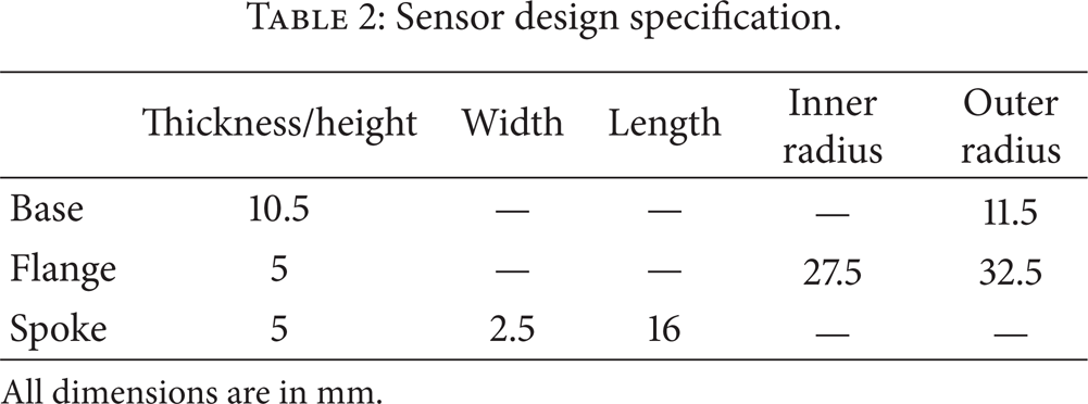
All dimensions are in mm.
The elastic elements of designed flexure are the spokes. These spokes are responsible for the deformation or the twist when the torque is applied on the joint link. In addition, any torque generated by the motors is transmitted through the base to the flange via these spokes, causing the spokes to deform. This deformation of spokes creates resistance changes of strain gauges mounted on the spokes, as shown in Figure 4. 8 strain gauges are installed on 4 spokes, respectively, forming two symmetrical Wheatstone bridge circuits. Then, the sensor sensitivity S can be calculated from sensor output voltage ΔU and applied torque T as follows:


The designed sensor: (a) front view and (b) side view.
The output voltage of the full-bridge circuit is known and can be expressed as:

where R is resistance of a single strain gauge, e x is excitation voltage of Wheatstone bridge circuits. ∊ and k are strain and gage factor of the strain gauge, respectively. Then, sensor sensitivity S can be derived as

Equation (3) shows that the sensor sensitivity is determined by the strain of the spokes under rated torque when the strain gauge and excitation voltage of Wheatstone bridge circuits have been selected.
3. Simulation
3.1. Stress and Deformation Analysis
FEM software (ANSYS) is applied to simulate and analyze the stress and deformation of the sensor. The final performance of the designed sensor, to a great extent, depends on material properties. Duralumin alloy is considered for simulation because of its lightweight, good mechanical, physical performance as shown in Table 3. Then, the overload performance is analyzed by ANSYS. The sensor is design to withstand the torque of 5 Nm; thus, 10 Nm is tested for the designed torque sensor. Figure 5(a) shows the tangential deformation of the sensor, and Figure 5(b) shows FEM stress analysis, under torque of 10 Nm. The maximum stress value obtained from analysis is σ = 195 MPa this value is less than the material (duralumin alloy) σyield stress, that is, yield = 245 MPa.
Main performance index of 2A12-T4 duralumin alloy.
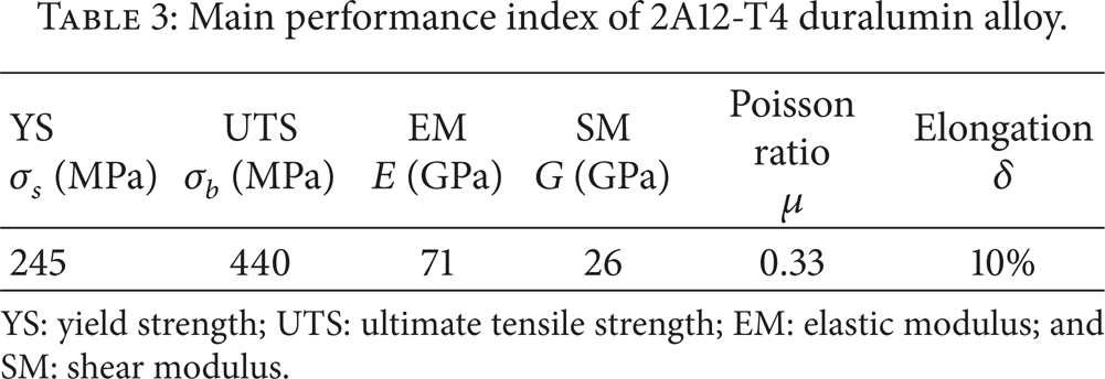
YS: yield strength; UTS: ultimate tensile strength; EM: elastic modulus; and SM: shear modulus.

Simulation result at 10 Nm torque: (a) deformation (m) and (b) stress (Pa).
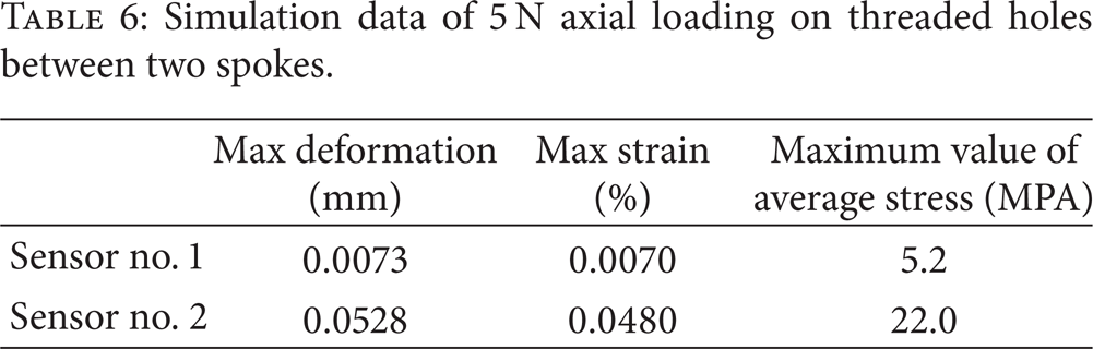
In addition, the effect of axial loading is also analyzed by ANSYS. Besides the designed sensor (sensor #1), another spoke-type sensing structure (sensor #2) is designed to test as well, whose design concept is from [13]. The design specifications of sensor #2 are listed in Table 4. Axial loading of 5 N is applied on threaded holes towards single spoke and threaded holes between two spokes, respectively. Simulation results are shown in Figures 6 and 7, and the simulated data of two sensors is shown in Tables 5 and 6. Thus, sensor #1 is found less deformation (0.0073 mm) than sensor #2 (0.0528 mm) under the same axial loading, that is, having a good stability against axial forces.
Sensor no. 2 design specification.

All dimensions are in mm.
Simulation data of 5 N axial loading on threaded holes towards single spoke.

Simulation data of 5 N axial loading on threaded holes between two spokes.
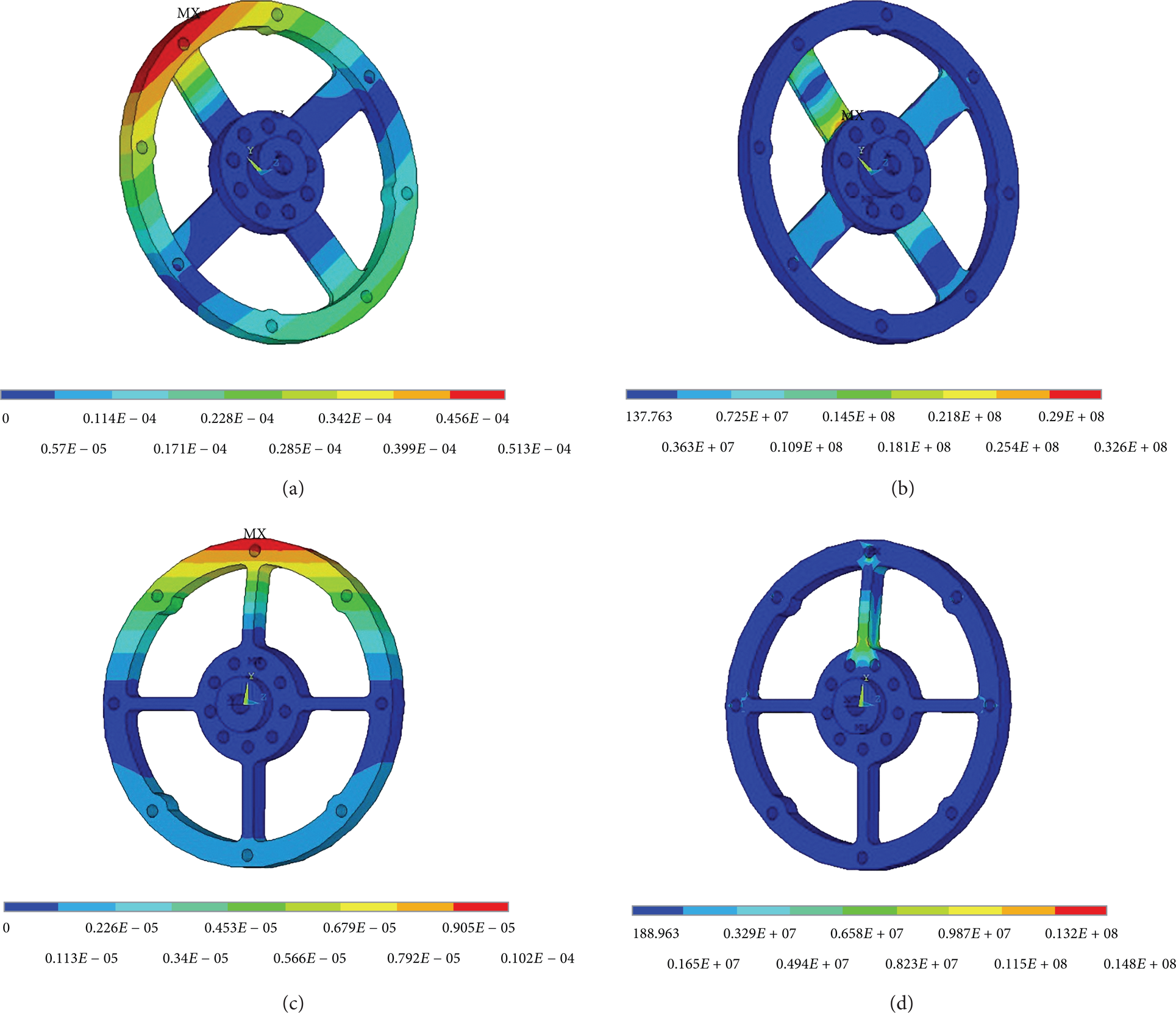
Simulation result of 5 N axial loading on threaded holes towards single spoke: (a) deformation (sensor no. 2, m) and (b) stress (sensor no. 2, Pa) and (c) deformation (sensor no. 1, m) and (d) stress (sensor no. 1, Pa).

Simulation result of 5 N axial loading on threaded holes between two spokes: (a) deformation (sensor no. 2, m) and (b) stress (sensor no. 2, Pa) and (c) deformation (sensor no. 1, m) and (d) stress (sensor no. 1, Pa).
3.2. Temperature Effect Analysis
According to the design requirements and mission types, a temperature control system is normally installed inside the joint of space manipulators, which makes the joints working in a certain range of temperature. However, as ambient temperature varying in large range may occur during the space missions, the capacity of wide operating temperature within a short period of time for the designed sensor is needed, which increases reliability of the joint control system at the same time.
As mentioned in Section 2, temperature variations affect both the gauge factor of strain gauges and the elastic modulus of elastic elements of designed flexure, as shown in Figures 2 (b) and 8 (a). Then, the relative error of the output voltage of the full-bridge circuit is evaluated by (2), which indicates that output voltage ΔU ∝ k and ∝ 1/E. Parameters k and E are the gage factor of strain gauges and elastic modulus of the elastic elements of designed flexure, respectively. Simulation results are shown in Figure 8 (b). Thus, the temperature effect is found weak of 0°C ∼ 50°C, and the relative error under rated load is less than 6% in the whole operating temperature range, which is a benefit for compensation of the determinate error caused by temperature variations.

(a) Elastic modulus variation with temperature for 2A12-T4 duralumin alloy. (b) Variation of relative error of the output voltage of the full-bridge circuit with temperature under rated load.
4. Experiments and Results
As shown in Figure 9, the designed flexure is machined from a single piece of duralumin alloy. In order to eliminate the measurement of sensor error caused by axis misalignment error between the sensor, and the flexspline of harmonic drive gear, 8 strain gauges are installed on 4 spokes, respectively, forming two symmetrical Wheatstone bridge circuits. The bridge circuit is excited by single-regulated 5 V DC voltages. Besides the second-order Butterworth filter designed in the torque sensor processing circuit, a Kalman filter implemented in FPGA has also been adopted to reduce the biggish noise of torque information. The output of the sensor processing circuit is interfaced with the FPGA platform, which is used for data acquisition and processing.

The manufactured sensor.
Figure 10 shows the 3D model of the test bench designed for calibration and experimentation of the sensor. The test bench consists of a fixed support, a fixed shaft, the torque sensor, and a base to hold the fixed support. Fixed shaft connects the base of the sensor with the fixed support. The test load is applied to the flange of sensor. Moreover, due to the limitation of experimentation, performances of the sensor under high temperature environment are not considered in the experiments, becoming a part of future work.

3D model of: (a) Test system. (b) Fixed shaft. (c) Fixed support.
For experiments, the sensor was calibrated by applying known torques and measuring the output signals from the sensor. The desired torque was achieved by hanging known weight of mass m at a distance d = 0.03 m. Torque can be calculated by using (4) as follows:

4.1. Linearity
To test the linearity of the sensor, static torque is applied by hanging load at the flange of sensor. The experiment is conducted more than 50 times to ensure the accuracy and repeatability of the sensor. The experiment data for linearity test with error is shown in Table 7. Then, a fitting line is calculated using (5), which is determined by fitting linear function of data analysis and graphing software OriginPro. Figure 11 shows the scatter diagram of the experiment results with the calculated fitting linear. This straight line is almost connected to each point, indicating good linearity of the designed sensor as follow:

Experiment data for linearity test with error.


Experiment results of linearity.
4.2. Hysteresis
Hysteresis test is also carried out for the designed sensor by applying load in ascending and descending manners. The experiment data and error between loading and unloading are shown in Table 8, and the graphs of hysteresis and error are shown in Figures 12 (a) and 12 (b), respectively.
Experiment data for hysteresis test with error.


Experiments results: (a) hysteresis and (b) error.
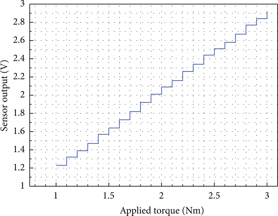
4.3. Resolution
Experiment was done to determine the resolution of the designed torque sensor, that is, the smallest increment that the sensor can reliably detect. The torque is applied on the sensor with 0.1 Nm increment from 1 Nm to 3 Nm by varying weight of the applied load. Stair-type graph for resolution test is shown in Figure 13. The max output span at any applied torque is about 0.03 V, and the min step size is 0.07 V with an average of 0.086 V, as listed in Table 9. Thus, the designed sensor can reliably detect torque increment of 0.1 Nm.
Experiment data for resolution test.

Experimental results of applied torque with 0.1 Nm increment.
4.4. Repeatability
Moreover, the designed sensor undergoes repeatability test as well. Table 10 shows part of the experiment data for the test, which is measured more than 50 times for each applied torque value. It was found that the sensor accurately detects the applied torque in the range of ±0.04 V. This shows the sensor's tendency to produce the outputs as much closer to targeted values.
Experiment data for repeatability test.

5. Conclusion
In this paper, a compact, lightweight, and monolithic joint torque sensor for space manipulator is developed. The thickness of sensor is reduced up to 10.5 mm, and the designed sensor can successfully detect torque up to 5 Nm. Strain gauge technique is used to detect the angular displacement. As ambient temperature varying in large range in space, strain gauge temperature effects and temperature compensation for the sensor are considered. To reduce the interferences by axial forces, the structural optimization for the sensing element is carried out. Simulation was done by FEM software ANSYS. The result of the simulation shows enough load capacity and low sensitivity over unwanted loads of the sensor. In addition, this sensor proves high repeatability and linearity in the experiments. The designed sensor also shows good stability against axial forces. The least count that the sensor can detect with high precision is 0.1 Nm. Thus, the performances of the designed joint torque sensor match requirements from space missions. Future work is to increase the precision of the joint torque sensor and validate performance and effectiveness of the sensor in actual space environment.
Footnotes
Acknowledgments
This research has been supported by a Grant from the National High Technology Research and Development Program of China (863 Program) (nos. 2005AA742030 and 2010AA7090304) and the Major State Basic Research Development Program of China (973 Program) (no. 2013CB733005).