
Abstract
In rechargeable wireless sensor networks (R-WSNs), sensors have to adjust their duty cycles continuously owing to sporadic availability of energy and operate in a very low duty cycle because of current energy conversion technical limitations. Even though the network lifetime is not the main problem, packet delivery latency is critical because a sensor is in the dormant state most of the time in R-WSNs. These unique characteristics pose a new challenge for routing protocol design over traditional energy-static sensor networks. In this work, we introduce a routing protocol based on anycast communications technology, a novel design to minimize packet delivery latency for forest monitoring in R-WSNs. The key idea is to let a sender choose a closest neighbor to forward packets from forwarding candidates and a nearest sink node to accept the packet from all sinks. For multiple source nodes, we introduce an anycast technology based on Tabu search for each source establishing a minimal E2E delay routing path to reach anyone sinks. Through extensive simulation and experiments, we demonstrate that our anycast scheme based on Tabu search is efficient to provide smallest packets delivery latency in R-WSNs.
1. Introduction
Wireless sensor networks (WSNs), a promising technology, have been a topic of much interest to researchers due to their wide-ranging applications. For example, they have been used for military applications, environmental applications, health applications, and home applications [1, 2]. However, a fundamental problem in WSNs is the limited lifetime of sensor nodes. To this end, a significant amount of work has been carried out across the protocol stack to prolong the lifetime of WSNs. Examples of which include energy-efficient medium access control (MAC) protocols [3], duty-cycling strategies [4], energy-efficient routing [5], and topology control mechanisms [6]. Other examples can be found in [7, 8] and references therein.
An interesting approach to extend the lifetime of sensor nodes is the use of energy harvesting, which refers to harness energy from the environment or other source. Sensor nodes will equip them with rechargeable technologies that convert sources such as body heat [9], foot strike [10], and finger strokes [11] into electricity, such as a rechargeable battery or an ultracapacitor [12]. The energy from surrounding environment is free, unlimited, and environment friendly. Assuming energy neutral operation [13], a sensor node can operate perpetually if the harvested energy is used at an appropriate rate. Note that a harvesting node is said to achieve energy-neutral operation if the energy used is always less than the energy harvested, and the desired performance level can be supported in a given harvesting environment. The energy rechargeable device and energy storage device as the energy supplement components of R-WSNs replace the battery that is used in traditional WSNs (T-WSNs), which is the key difference between the new-fashioned WSNs and T-WSNs. The system architecture of an energy-powered sensor node is illustrated in Figure 1.
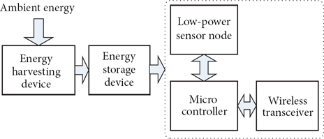
Components of a energy-powered sensor node.
In this so-called energy harvesting or rechargeable WSNs (R-WSNs), although their lifetime is less of an issue, the available energy on nodes varies dramatically over time owing to the varying environment conditions. For example, a node that relies on the sun will extract more energy on sunny days as compared to when it is cloudy and extract no energy at night at all. To regulate energy consumption, nodes adapt their duty cycle according to available energy, which leads to high packet delivery latency or sleep delay [3]. Sleep latency is the duration from the moment a packet is ready at the sender to the moment the destined receiver accepts the packet [14]. The key contributor to delay is the fact that if a node wants to communicate with a neighboring node, it has to wait for the corresponding neighbor to wake up. Sleep latency is usually in the order of seconds, which is much longer than other delivery latencies, such as processing delay, transmission delay, and propagation delay. The end-to-end (E2E) problem is more critical in R-WSNs than that in WSNs.
Anycast technology is utilized widely to solve the data transmission problems for multiple sinks deployed in WSNs. The paradigm of anycast communications [15, 16], also termed one-to-any communications, become very important to a network with multiple sinks: when a sensor node produces data, it has to send it to any neighbor node or sink available. A neighbor node or a sink selection strategy is to choose for each source a neighbor or a sink arbitrarily. An alternative strategy is to route data to the closest neighbor node or sink. Assuming that the sources and the sinks are uniformly distributed throughout the network, this simple strategy is assumed to improve data transmission efficiency and reduce latency.
In a nutshell, we propose a distributed anycast transmission scheme to reduce the E2E delay for sources-to-sink communications in R-WSNs. To the best of our knowledge, this is the first generic work that studies the use of anycast technology to reduce end-to-end delays in R-WSNs. The remainder of this paper is organized as follows. In Section 2, we present a number of existing anycast routing protocols and E2E latency guarantee solutions, while in Section 3 the motivation is provided. In Section 4, we present our method and design. Section 5 provides the analysis of our algorithm. Section 6 contains experimental results. Conclusions are presented in Section 7.
2. Related Work
Anycast is an important paradigm for a wireless sensor network in terms of resource, robustness, and efficiency for replicated service applications [17]. Routing protocols based upon anycast scheme are in accordance with the agreement [18], the extended model usually in the tree by hop count, physical interval, or time intervals for unit, to build an anycast tree and query is transported along the most fitting anycast tree [19]. The anycast scheme is utilized to cope with sink selection in routing protocol design for WSNs and improve the performance of routing protocol widely, whose ultimate goal is to prolong the network lifetime [20]. Other examples can be found in [21–23], and references therein. Even though multiple sinks are deployed in R-WSNs and sensor should also select one sink from the sink group to deliver packets, network lifetime is not a problem. It is impossible to rely on a fixed routing path for data transmission because of the dynamic topology attributing to dynamical energy supply in R-WSNs. So these routing protocols, which are designed for WSNs, do not adapt to R-WSNs. In particular, as one of the most important characteristics, low-duty cycle is not considered in routing design.
Various routing protocols have been proposed for low-duty-cycle sensor networks, for example, [24, 25]. Dynamic switch based forwarding (DSF) [26] is proposed for networks with possibly unreliable communication links and extremely low duty cycle, which utilizes forwarding sequence to reduce the time spent on transmitting a packet successfully at each hop in order to achieve expected communication delay and energy consumption. SCP [27] is designed for ultralow duty cycle (0.1%) sensor networks, which utilizes low power listening technique to poll a channel in order to save energy and reduce delay. Gu et al. [28] introduce two methods, including increasing duty cycle at individual node and place sink nodes to bound communication delay. These schemes encounter critical tradeoffs between network lifetime and data delivery latency. In R-WSNs, the lifetime is not the main problem which can be maximized by operating in an energy neutral mode for nodes.
By considering the dynamical energy supply for sensor nodes, Noh et al. introduce a duty-cycle-based low-latency geographic routing for asynchronous R-WSNs [29]. They propose D-APOLLO, an algorithm that periodically selects an appropriate duty cycle of each node to achieve minimum latency, which is based on the currently estimated energy by predicting energy consumption and energy expected from harvesting device. Sun and Xu [30] present an algorithm to reduce delivery delay that allows a sensor with packets to be sent dynamically select a forwarder from a forwarding sequence set, in which potential forwarders are sorted into the order of their wake-up time. Gu and He [31] introduce a method to increase duty cycle by strategically adding wake-up slots to nodes to reduce end-to-end delay to within a given bound. Gu et al. [32] further present energy synchronized communication (ESC) to synchronize the harvested energy at an individual node to minimize communication delays by shuffling and adjusting the working schedule of a node under different rates of energy harvest. However, more energy will be consumed, and collision will be serious in these protocols.
Different from earlier works, which either focus on static battery-powered network or minimize delay under energy constraints, in this work, we present a routing protocol based on anycast communications for forest monitoring in R-WSNs. Anycast scheme is used to resolve forwarding node selection for sensor node, including to choose an optimal neighbor node to forward packets from forwarding candidates and an optimal sink node to accept the packet from all sinks. In summary, on observing the lack of anycast technique's consideration for reducing communication delay in existing power management protocols. We introduce the first generic routing protocol algorithm with anycast scheme in R-WSNs. To the best of our knowledge, there was no prior work studying the problem of delay reduction using anycast.
3. Motivation
The motivation through the work is originated from our empirical experience of deploying rechargeable wireless sensor networks. In this work, we focus on using the harvested energy as the only energy source. The energy barely comes from the solar form. Therefore, the energy rate is generated only when there is sufficient sunlight or artificial light.
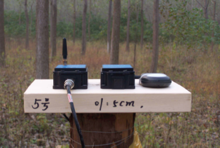
First, The dynamic duty cycle of a node is the most intuitive characteristics of R-WSNs. For studying the duty cycle of the node over time, we deploy a solar-powered sensor in an open field, as is shown in Figure 2. We assume the power consumption requirements of 83.1 μW in receive state and 76.2 μW in transmit state, which is presented in [33]. Assume the area of solar panel is 10 cm2 to recharge energy for sensor nodes and the solar-energy conversion efficiency is about 10% [34, 35]. When a sensor node lies in direct sunlight at 12 am, the power density can reach 3700 μW/cm2, energy harvesting rate is 320 mW, and the duty cycle achievable by the Crossbow MICAz can reach about 45%. However, when the sensor node lies indoor, the power density is about 320 μW/cm2, the energy harvesting rate is 320 μW, and the duty cycle is estimated to be about 0.04% [33]. Therefore, the energy harvesting sensor networks are an environment-dependent network.

Experiment Site.
Second, the harvesting energy is still significantly lower than the power consumption for each wireless sensor node. Thus, node has to operate in a very low duty cycle which means that a node has to be activated shortly and stay at the sleep state most of the time in order to recharge. In our work, some experiments about the duty cycles of rechargeable sensor nodes were done. Figure 3 shows the affordable duty cycle of a node in three different weather conditions in spring. For example, a sensor CC2500 is used as the test device and lies outdoors. When the cloud area accounts for 1–10% of the sky, the duty cycles of a rechargeable node are ranged from 0.001% to 32% over 24 hours. From our empirical measurement results, a node can only operate about 3.5 hours if its duty cycle is over 20% using the total energy extracted from ambient environment over 24 hours. It is a long time for a packet reaching a sink. Therefore, quality routing protocol is critical for reducing transmission time in R-WSNs.
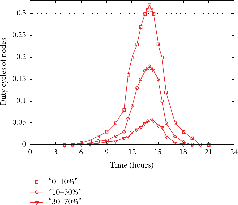
The duty cycle of a node over 24 hours.
Third, in R-WSNs, it is unrealistic for a sensor node set fixed duty cycle to meet special requirements. Actually, the duty cycle of a node is adjusted passively according to the energy harvesting rate, which is significantly distinct from that in traditional WSNs that a sensor node can change its duty cycle freely only if it needs to do this. Even though various nodes perhaps lay in the same environment conditions, each node may harvest different amounts of energy due to some unpredictable factors, like a diverse solar panel angle. Therefore, the duty cycles of nodes may be different from each other. These characteristics have not been considered in T-WSNs, which will pose significantly challenges for routing protocol design in R-WSNs.
In R-WSNs, considering the dynamics energy supply, low duty cycle, and different harvested energy rate, the packet delivery latency is difficult to predicate and more critical than that of traditional WSNs, which affects the applications and popularization of R-WSNs significantly. In this work, we provide a generic and efficient anycast routing protocol for owning those characteristic's sensor networks. To the best of our knowledge, few works have studied on the routing protocol for energy synchronization, low duty cycle, and duty cycle dynamics utilizing the anycast technologies.
4. Method and Design
4.1. Network Model
Consider a static rechargeable wireless sensor network modeled as an undirected graph
The working time of all sensor nodes are divided into periodic working schedules, and every node shares its schedule with its neighbors. The working schedule consists of a set of active instances, during which a sensor node can transmit and receive packets. The transmitting and receiving activity happens in the active state. There are two situations for a dormant sensor node to wake up. The node has packets to transmit, or it is scheduled to the active state. In other words, a sensor node can wake up to transmit a packet at any time only if its receiver is in the active state but can receive a packet only when it is in the active state itself.
For all sensor nodes, since their neighboring nodes switch between active and dormant states regularly, the transmission between a pair of nodes becomes time-dependent strictly. In the paper, let the duration of periodic working schedules be t which can be divided into a sequence of time instances with length τ. The duration of τ is the unit of working time for an activity. For a node, when it is in the active state within period time t, its working schedules can be represented by a set of time instances, which contains one or multiple time instances with length τ.
For explaining the active and dormant activities utilizing the working schedule and time instance, let

Example of working schedule.
In order to achieve minimal E2E delay from source node to a sink, minimal sleep latency in each one-hop transmission is expected to reach. Firstly, every node starts to broadcast its existence and working schedule to its two adjacent neighbors. Second, every node continues to broadcast its one neighbor's working schedule to another neighbor node. Followed by neighbor discovery, every node knows the working schedules of adjacent neighbors and two-hop away node. Each node calculates the sleep latency between itself and its neighbor node and sends the result to its neighbor node. Finally, the sink node calculates the E2E delay from source node to the sink and nodes in the network start to execute delay maintenance process.
4.2. Description of E2E Delay
In the work, in order to calculate packet delivery latency or sleep delay, we assume that two sensor nodes are in a nodes group set

E2E Delay. For a packet ready at source node i, the delay to reach the m-hop away sink node s is the sum of single-hop sleep latency. Consequently, it can be formulated as
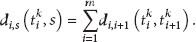
From (2), we know that the E2E delay is affected by the working schedules of nodes and the number of hops from source node to a sink. Even though the working schedules of nodes are on the influence of energy supplement and hard to be revised, we can choose a short path from source to a sink. A short path is created based on nodes' working schedules. In R-WSNs, a path with a minimal number of nodes is maybe not able to provide the smallest E2E delay. Therefore, when a path is established from source to the sink, minimal E2E delay (
4.3. Description of the Anycast Scheme
In the previous analysis, we know that the E2E delay is significantly affected by the working schedules of nodes and the number of hops while the number of hops to reach the sink is affected by the number of neighbor nodes of the sender, which is affected by the remaining energy of the sender. In the following section, we introduce the energy controlling scheme, neighbor node discovery, and an anycast scheme to achieve minimal E2E delay from all sensor nodes to a sink in R-WSNs. For the sake of clarity, we describe the scenario with a single sink node, which can be extended easily for scenarios with multiple sink nodes.
4.3.1. Energy Controlling Scheme and Neighbor Discovery
The assumptions, a node can wake up and transmit a packet at any time, which requires it has basic energy to support this suppose. In other words, a node should have enough energy to initiate a transmission with at least one neighbor at anytime. The energy needed to afford a transmission is different from each other, which depends on the distance between them. In this part, we introduce an energy controlling scheme and neighbor discovery based on energy controlling scheme.
In R-WSNs, we assume that
If
To further demonstrate energy controlling scheme affecting the neighbor discovery, a simple example is provided, as shown in Figure 5. In the distribute network, the working schedule of node i is set as
Several nodes are deployed.
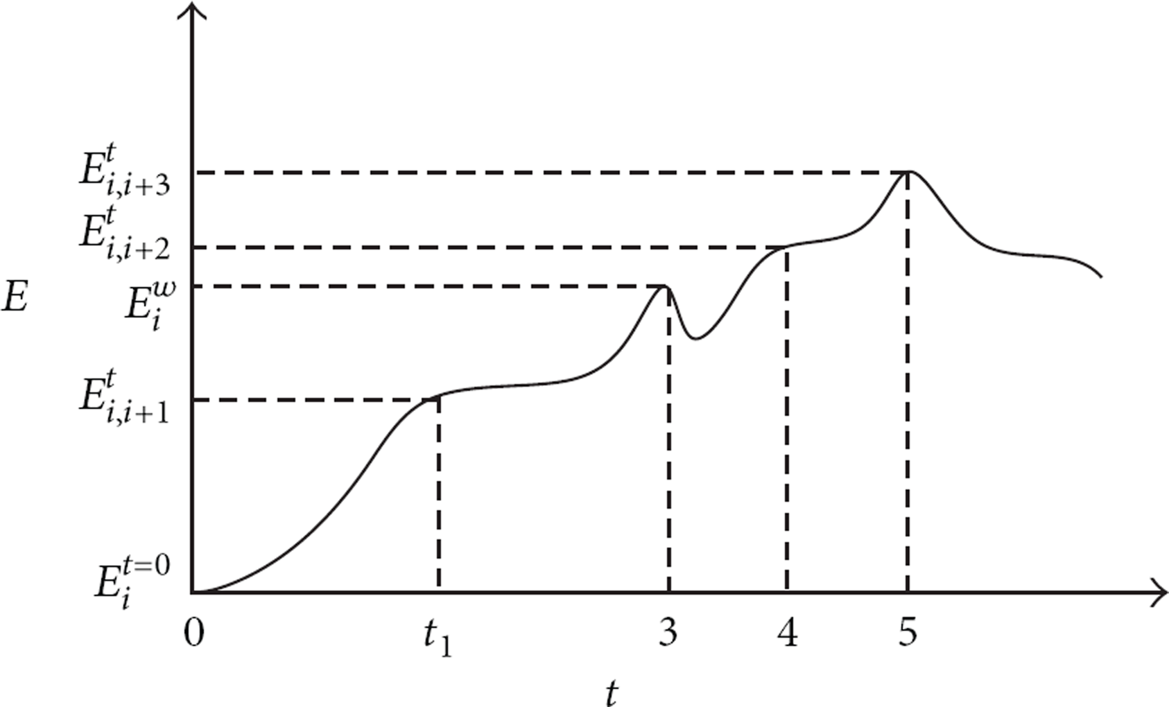
Energy of node i over time.
We assume that node i generates a packet at the time
Each node will establish a neighbor table based on energy controlling scheme, which contains potential receivers. The neighbor table is a stack, which holds adjacent neighbors of sender and the nearest node is put at the bottom of the stack. Figure 7 shows the neighbor table of node i created over time. If the node i has enough energy to communicate with its neighbor node

Neighbor table of node i over time.
4.3.2. Neighbor Discovery Based on Anycast Scheme
In R-WSNs, the anycast technology is utilized to let one sensor choose another adjacent node from its neighbor table to accept packets. Therefore, the anycast technology can be used to resolve the one-to-anyone communication problems in R-WSNs. In this part, we will discuss how a sensor chooses one neighbor from its neighbor table and one sink from multiple destinations.
After a sensor node i generates or accepts a packet at the time
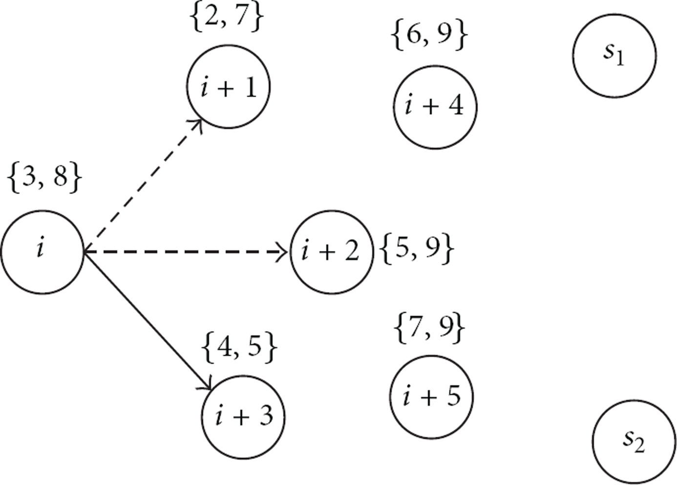
To further demonstrate the selection method for getting a next-hop node from the neighbor table, we provide an example shown in Figure 8. We assume that a packet is generated at the time
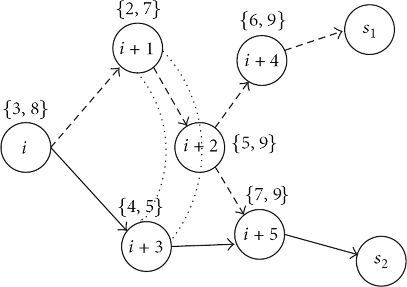
Example of anycast transmission with one source.
In order to calculate the value of E2E sleep latency from a source node to a sink, we extend the neighbor-table form. The new neighbor table records not only the neighbors but also the E2E delay from the node to one sink. The recording delay in the new table is in the form of

The new neighbor table for node i.
After joining the networks, each sensor will calculate the E2E delay from itself to any one sink and store the value into the neighbor table. The delay calculation is initiated from the surrounding of a sink, firstly, and other far nodes will calculate the sleep delay to them according to their delay recording values. Consequently, each sensor node will establish a neighbor table containing all neighbor nodes and corresponding sleep delay. In the process of creating a neighbor table, a node does not master all sensors' information except for adjacent neighbors.
4.4. The Anycast Transmission Scheme for Multiple Senders
4.4.1. The Anycast Technology for Multiple Senders
In R-WSNs, there are usually multiple senders deployed for collecting data, which poses a high challenge for routing protocol design. A receiver can only accept packet from one sender at a fixed point of time, which means if a sender accepts a packet from one sender at the time t, it cannot accept any packet from other senders at the same time. Multiple senders have to contend with active instance of neighbor nodes. If a sensor has priority to use the active instance of one neighbor node, the active instance cannot be utilized by other sensor nodes owning the same neighbor.
An example is provided to demonstrate the anycast transmission scheme for multiple senders, as is shown in Figure 10. Node i and node

Example of anycast transmission with multiple senders.

Example of anycast transmission.
4.4.2. The Anycast Technology Based on Tabu Search for Multiple Senders
In this section, we propose a new anycast routing protocol scheme based on heuristic Tabu Search. The idea is to use Tabu Search method for all sources to achieve minimal E2E delay routing packets from the sources to any one sink in a distribute network. The Tabu Search is an advance local research method that uses rules and some mechanisms to lead toward the optimal solution. The Tabu research requires an initial solution and structure of neighbors. This method proceeds by moving from a solution to another. For each iteration, all the possible solutions are inspected, and the best one is selected.
After a sensor node generates or receives a packet, it will send the packet to any one of its neighbor nodes only if they are in active state, and the receiver continues to forward the packet to next node until the packet reaches a sink. In order to utilize the active instances of sensor nodes effectively and improve the transmission efficiently, the anycast technology based on Tabu search is utilized to achieve the best neighbor selection and sinks selection in R-WSNs.
The core of anycast routing protocol based on Tabu search for R-WSNs is to select a nearest sink as destination. The problem of optimal sink selection can be formulated as follows. Consider a case of n sources and a group of k sink nodes where

The Anycast Technology Based on Tabu Search
For a source node i, there are m paths reaching at least a sink, When
Neighbor Node Selection. For a network with multiple source nodes, the source node with high priority has the priority to choose a neighbor to receive its packet, which is selected from its neighbor table using anycast technology. In the process of selection, only one node is chosen as long as it is in the active state when the sender delivers its packet. After the first source selection, the second node starts to choose its neighbor node and the process of node neighbor selection is repeated. The neighbor node selection has been discussed in the previous section.
Tabu List. Tabu list is an important part in Tabu search, and it prevents the search from short-term cycling. For a sensor node, its Tabu list contains the instances of its neighbors, which is empty initially and dynamical over time. Since a node only receives a packet from at most one sender at a point of time, it is impossible to accept any packet from other nodes simultaneously. Therefore, if an instance of a sensor node is utilized to receive a packet, the instance cannot be used another time at the same duration. The instances are removed from working schedule of sensor node and moved to Tabu list in order to avoid other nodes using the instance again. Other sensor nodes will not consider the active instances of neighbor nodes if they are in Tabu list when communicating with these nodes.
Tabu Length. Tabu length is the iteration number of a feasible solution that is forbidden. That is, for a certain number less than the Tabu length, the instance is not allowed for other applications if it is in the Tabu list. If the Tabu list is full, the instance that is the longest in the Tabu list is removed. In this paper, the Tabu length is set according to the requirements of a sensor node. If a sensor node decides to communicate with its neighbor node at the time t for
The program is stopped when its iteration number exceeds the limit. Similarly, another purpose is to limit the occurrence number of a solution or an objective value. The program will also terminate when the related numbers exceed the corresponding limit. When a sensor node wants to stop transmission even if
In order to further demonstrate the anycast transmission scheme based on Tabu search for multiple senders, we analyze transmission from node i as shown in Figure 10. In Figure 12, three neighbor tables of node There are at least four paths reaching at least a sink node. Consider Since

The neighbor tables of node
The bast routing path is outputted after the program termination of node i. While the active instances used in the path are moved to Tabu list, now, we assume node
The anycast technology based on Tabu search can achieve three purposes for multiple source nodes in R-WSNs. Firstly, the anycast scheme can be utilized to achieve optimal neighbor's and sink's selection. Secondly, a sensor node can establish a routing path with minimal E2E delay to reach at least a sink node. Third, in the process of creating a path, a sensor does not need to know which sink will receive the packet before the transmission finished, which means that the sink selection is transparent for sensor nodes. At the same time, anycast technology based on Tabu search can release the pressure of transmission for sinks effectively, which benefits from multiple sinks sharing the packets' transmission.
5. Analysis
5.1. Experiment Setup
In the simulation, up to
What we use consists of a solar panel optimized for outdoor use, two eZ430-RF2500T target boards and one AAA battery pack, which is rechargeable and can be recharged repeatedly. The target board comprises the TIMSP430 microcontroller, CC2500 radio transceiver, and an on-board antenna. The CC2500 radio transceiver operates in the 2.4 GHz band with data rate of 250 kbps and is designed for low power wireless applications. The harvested energy is stored in EnerChip, a thin-film rechargeable energy storage device with low self-discharge manufactured by Cymbet, as is shown in Figure 13.
A sensor node is deployed outdoors.
Our projects get the support of government funds and Provincial Science and Technology Center (PSTC). We have deployed a large number of sensor nodes and monitoring system in the ZiJin Mountain and Nanjing Forestry University (Nanjing City, China) (http://njfu00.h006.996h.cn/, the Internet site is valid from 2013-10 to 2014-10), which is used to collect various sensory data, which contains temperature, humidity, and illumination from a forest, as shown in Figure 14. One of our objectives is to maintain the attainability of the network for as long as possible and collect accurate and as much as possible data to support the research about forest, which is also demonstrated to be necessary for other applications of sensor networks. Hundreds of sensor nodes and multiple sinks are deployed in the two places to monitor the coverage area. Most of them are powered by two energy systems, including a rechargeable battery and a common battery together.

Sensor nodes are deployed in four monitoring stations.
5.2. System Performance Comparison
In order to understand the performance of our Routing Protocol for Anycast Communications (RPAC) under network settings; in this section, we provide an algorithm for performance comparison, which is proposed by Eu et al. [36]. In [36], an opportunistic routing protocol (EHOR) for multihop WSN-HEAP is introduced to resolve the optimal forwarder problem, which uses a region-based approach by grouping nodes together to reduce delay. We first compare the per-hop delay between our algorithm and EHOR under distinct duty cycles and number of sensors, as is shown in Figure 15. From Figure 15, we can know that the average delay per-hop in both algorithms decreases with the duty cycle increasing in three different scenarios, and the average delay of PRAC is obviously lower than the EHOR.

Delay per-hop of sensor node under different duty cycle and node density.
In scenario 1, up to 150 sensor nodes and 2 sinks are deployed. From Figure 15(a), we know that the delay per-hop of EHOR is always greater than that of our algorithm. In particular, when the duty cycle of a node decreases greatly, the delay of EHOR increases more quickly than that of the PRAC. From Figure 15(a), we can see if the duty cycle of a node is lower than 1%, the delay per-hop of sensor is lower about 5% than that of EHOR. In other words, when sensor nodes keep in low duty cycles, our algorithm will operate more efficiently than EHOR. Therefore, our algorithm is more stable than EHOR in delay performance. In the EHOR, all sensor nodes are divided into multiple regains based upon the distance to the sender within sensor transmission range. Only one node will be chosen as the forwarding node in each region, which depends on the remaining energy and the distance to the sink. Even though the EHOR can achieve to maximize goodput, E2E delay is as secondary performance metrics. In the process of transmission, the transmission power controlling technology has not been considered for each sensor node. Therefore, a sensor node cannot adjust its neighbor table timely, which cause the E2E delay to be higher than RPAC.
In scenario 2, 300 sensor nodes and 2 sinks are deployed. The nodes density increases significantly. From Figure 15(b), we know that the delay per-hop decreases greatly for both algorithms because a sensor node will have more neighbor nodes to receive its packets. When density of sensor nodes increases, since more sensor nodes will be contained within the neighbor table for each sensor node, it is easier for a sensor node to find a receiver when it wants to deliver a packet. For different duty cycles, the delay per-hop in our algorithm is always lower than that of EHOR. In the third scenario, we deploy more sinks in the monitoring field. Even though sensor node's density does not increases, the number of nodes lying in the path from source node to sink decreases. Therefore, the E2E delay that a packet is delivered from a source node to sink decreases. 300 sensor nodes and 4 sinks are deployed in scenario 3; the result is shown in Figure 15(c), the data tests and verifies our analysis.
Figures 15(d), 15(e), and 15(f) show the delay per-hop of the network under a different number of nodes when the duty cycles of sensor nodes are 1%, 3%, and 5%. From the three diagrams, we see that the delay per-hop decreases when the number of node's increases for both algorithms. If we improve the duty cycles of sensor nodes, the average delay per-hop of sensor's further declines. High duty cycles will cause the packet's delivery faster than before because sensor nodes will be in the active state more time to listen to the channel and ready to receive a packet. The figures illustrate that the delay per-hop of our algorithm is a little lower than that of EHOR for every different number of nodes and duty cycles.
The data generation rate of each sensor node is easy to be controlled, which depends upon the requirement of application. In our monitoring system, for an event-monitoring system, sensor will generate a data when it detects an occurrence of event or the timer reaches point in time. In fact, sensor node generates packets periodically or intermittently. Furthermore, the frequency of the data generation differs from one application to another. In our evaluation, we increase the data generation rate from 5% to 35% greatly in order to further understand the performance of our routing protocol and EHOR.
In the applications for real-time monitoring requirement, minimum transmission latency is demanded to ensure that the data are forwarded to destination as soon as possible. Therefore, we evaluate the average delay per-hop with the distinct number of nodes and data generation rate in the network. The result in Figure 17 shows the average delay per-hop as the data generation rate rises under a different number of sensor nodes and duty cycles of sensors in each protocol. Since the transmitting ratio rises substantially when a large number of packets are generated accumulated in sensor nodes; hence, the packet delivery delay rises significantly when we improve the data generate rate over time.
Figures 16(a), 16(b), and 16(c) show the average delay varying data generate rate under a different number of sensor nodes and sinks, respectively. From the three diagrams, we can know that the delay in EHOR is larger than that in our protocol in every data generate rate. In particular, the advantage of our algorithm is more notable when a large volume of data is generated. This is because packets reach the sink node after multiple retransmission by both protocol. The delay of our protocol is a slight lower than that of EHOR. The reason can be attributed to the more adaptable transmission scheme, since a sensor node can adjust its transmission power to control transmission range freely according to its remaining energy. In our protocol, more packets from nodes far away from the sink can reach the sink node because the source node can choose its neighbor node more flexible than that in EHOR.

Delay per-hop of sensor node under packet generation rate and node density.

The remain energy of sensor node over time.
Figures 16(d), 16(e), and 16(f) show the average delay under data generate rate increasing when the duty cycle of nodes is 1%, 3%, and 5%. From the diagrams, we see the delay per-hop increasing when we improve data generate rate from all three different duty cycles of sensors. When the duty cycles of sensor nodes increased, the average delay decreases significantly. High duty cycle means that a sensor node is in the active state more times and has more opportunities to receive or transmit a packet. Therefore, a packet is transmitted to the sink more quickly than before due to more neighbor nodes being ready to forward the packet. The delay of EHOR is a little higher than that of our protocol. For example, when the average duty cycle of a sensor node is 5% and the data generate rate is 30%, the delay of EHOR is about 2% taller than that of our algorithm.
6. System Implementation
6.1. Experiment Setup
In addition to large-scale network simulations, we deploy 16 nodes and a sink in a distribute network to further explain the energy of sensor node changing over time. Packet is generated from a source node and will be transmitted to the sink node. Other nodes can forward the packets from source node to the sink. After deployment, every node initiates to generate working schedule randomly with 20% duty cycle, which means every node can generate only average two active instances within each period time. Each sensor is equipped with a rechargeable battery, which owns the same storage capacity. When a sensor node joins the network, it has to recharge itself and let its remaining energy beyond a certain value to ensure that it can transmit a packet to its neighbor at any time.
6.2. System Insights
After being deployed in the monitoring area, every node initiates to broadcast its existence and working schedule to its adjacent neighbors. Followed by neighbor discovery, every node knows the working schedules of neighbors. When a packet is generated from the source node, the packet is forwarded from the source node to the sink node utilizing anycast transmission scheme based on Tabu search. The neighbor node selection is on the influence of remaining energy of the sensor node. To further illustrate the remaining energy changing over time, we monitor the battery of sensor in the process of packet delivery. Remaining energy of all sensor nodes, including
In our experiments, one unit of time equals about 4 ms, maximum storage capacity of a temporary battery is about 300 μW, and surplus energy will be stored in another battery. Figure 17(a) shows the remaining energy of a sensor whose ID is
The energy of the sensor whose ID is 3 over a period unit time is shown in Figure 17(c). The energy of node 3 reaches about 180 when the time is 200. Then, a packet coming from its neighbor and node 3 wakes up itself to receive the packet and stores the packet in its data buffer. The energy of node 3 decreases to 75 after receiving the packet. From the time 250 to 550, node 3 continues to recharge itself and has the energy about 150 at the time 550. At the same time, the sensor listens to the channel to check whether there is a packet coming from its neighbors utilizing weak sensing device in order to save energy. Even though there are no packets being in the channel, the sensor has wasted a little energy for channel listening. The energy of sensor node 3 reaches about 270 at the time 700. When node 3 finds that one neighbor will wake up at the time 700 by checking its neighbor table, node 3 listens to the channel and is ready to send the packet to its neighbor. If the channel is idle, the packet will be forwarded to its neighbor from node
7. Conclusion
In this work, we first define the network model and elaborate on the packet delivery process. The unique characteristics of R-WSNs cause that packet delivery latency is critical. To improve data transmission efficiency, we introduce a routing protocol based on anycast communications technology, a novel design to minimize packet delivery latency from source node to the sink for forest monitoring in R-WSNs, which is particularly designed for low-duty-cycle and dynamical duty-cycle wireless sensor networks. To our knowledge, this is the first work on routing protocol that utilizes anycast scheme and Tabu search to establish minimal E2E delay paths. In our design, each sender chooses a nearest neighbor to forward packets from forwarding candidates and a closest sink node to accept the packet utilizing anycast scheme.
For multiple source nodes, we provide an anycast technology based on Tabu search for each source node establishing a routing path with minimal E2E delay to reach at least a sink. For establishing the smallest delay path, we propose a mechanism of the heuristic Tabu search solution. Through extensive simulation and experiments, we demonstrate our anycast scheme based on that Tabu search approaches the optimal performance and achieves a shorter average with less than about 8% latency over traditional method in various network settings. The anycast routing protocol based on Tabu search proposed in the paper is designed for the scenario where the working schedules of sensor nodes are fixed. In the future, we shall extend our work into the scenario where working schedules of sensor can be adjusted flexibly to provide better performance.
Footnotes
Conflict of Interests
The authors declare that there is no conflict of interests regarding the publication of this paper.
Acknowledgments
This work was supported in part by The Six Talent of Jiangsu Province under Grant DZXX-149-148. The authors also received two projects funded by the Priority Academic Program Development (PAPD) of Jiangsu Higher Education Institutions and the Research of Modern Educational Technology of Jiangsu Province under Grant 2013-R-26936.