
Abstract
Broadcasting of emergency message (EM) in the vehicular Ad hoc networks (VANETs) plays a significant role in safety applications, which require immediate broadcasting of EM to the relevant vehicles located in the risk zone (RZ). This paper proposes an efficient emergency message broadcasting (EEMB) scheme in VANETs. This scheme aims at avoiding multiple accidents and reducing traffic jams by broadcasting EM at high speed and with low overhead. When an accident takes place, the crashed vehicle (CV) will choose the best relayer(s) and broadcast the EM. The relayer will also choose the best next relayer(s) and rebroadcast the EM further. This process continues until the EM covers the whole RZ. The EEMB scheme reduces the overhead caused by beacons by using the prediction method. Our proposed scheme also overcomes the network fragmentation problem either by choosing the vehicles moving in the opposite direction as the relayer(s) if there are no vehicles in the same direction or by using the store-carry-forward (SCF) mechanism when there are no vehicles moving in both directions. The simulation results have shown that the proposed scheme has better performance in terms of the risk zone latency (RZL) and the beacons overhead (BCO).
1. Introduction
Every year, many people lose their lives or get injured on roads and huge amounts of time and fuel are exhausted because of road accidents or traffic jams. According to the report of the Ministry of Public Security of the People's Republic of China, 65225 people were killed and 254075 injured in 2010 because of road accidents in China [1]. These losses would have been avoided or minimized, if drivers had been informed of the risk ahead in advance. For this reason, both of the research community and automotive industry have paid considerable attention to the vehicular ad hoc networks (VANETs) [2]. There are two main types of VANETs applications: safety and nonsafety applications. The purpose of safety applications is to increase the safety of both the passengers and the vehicles simultaneously. This purpose can be achieved by sending emergency messages (EMs) to the vehicles located in the risk zone (RZ) [3–5]. The purpose of nonsafety applications is to improve passenger's comfort and traffic efficiency and/or to optimize the path to a destination [6]. In the safety applications of VANETs, the EM needs to be disseminated to the RZ area which is usually several kilometers behind and in the same direction of the crashed vehicle (CV). Mostly, the one-hop range is just several hundreds of meters and cannot cover the total RZ. Thus a multihop propagation is needed during the dissemination [7]. Also, most safety applications will possibly work in a broadcast fashion since EM is useful to all vehicles surrounding the sender [8]. Flooding mechanism is the first broadcasting type. In flooding, a vehicle receiving an EM including a nonduplicate sequence number (SN) from the sender will rebroadcast it directly. Obviously, this mechanism is not efficient especially in the high network density, due to the huge number of EMs flooded in the network, which leads to broadcast storm problem [9]. To solve this problem, most researchers decrease the number of redundant rebroadcast messages by allowing only some of the vehicles to rebroadcast the message instead of letting every vehicle do that [10]. In this paper, an efficient emergency message broadcasting (EEMB) scheme has been proposed. According to this scheme, the EM is made to reach the relevant vehicles located in the RZ with low overhead and at a high speed. By applying the EEMB scheme, vehicles exchange a lower number of beacons to enable the sender to choose the best relayer(s) either in the same direction or in the opposite one and make the EM broadcast farther and faster.
The rest of this paper is organized as follows. Section 2 is a discussion of related work; Section 3 presents the operation and characteristics of the proposed scheme. In Section 4, the simulation and results are discussed. Finally, Section 5 is a conclusion.
2. Related Work
Broadcast schemes can be classified into two classes: receiver decision schemes and sender decision schemes. These classes with their main challenges will be explained in the first and second subsections. Network fragmentation issue will be identified in the last subsection.
2.1. Receiver Decision Schemes
In the receiver decision schemes [2, 11–13], the contention mechanism has been used for selecting the relayer. In this mechanism, every vehicle receives the EM and waits for a while before rebroadcasting the EM. This delay is called a waiting time (WT) and it can be calculated as a function of the distance between the vehicle and the sender. The farthest vehicle in the sender's transmission range will have the shortest WT, so it will be the relayer that will rebroadcast the EM farther. For the purpose of avoiding redundancy, the other vehicles located between this relayer and the sender will terminate their WT process when they know that the EM has been already rebroadcast. Therefore, only one vehicle will rebroadcast the EM [3, 10]. Both of urban multihop broadcast (UMB) [2] and smart broadcast (SB) [11] schemes are based on a request to broadcast (RTB)/clear to broadcast (CTB) handshake at each hop before transmitting the EM. A collision will take place when more than one vehicle sends the CTB packet simultaneously [14]. Since safety applications rely on multi-hop propagation, the use of the RTB/CTB handshake leads to long latency. In efficient directional broadcast (EDB) [12] and slotted 1-persistence [13] schemes, although the authors do not use the RTB/CTB handshake, they still use distance to calculate the WT. Therefore, in a sparse network, the WT is still long because the distance between the relayer and the sender is perhaps short. On the other hand, in a dense network, there will possibly be more than one vehicle that may have the same WT. In this case, the collision probability will increase resulting in the increase of latency.
2.2. Sender Decision Schemes
Contention mechanism, which is used in the receiver decision schemes, causes a long delay especially in the sparse network. This mechanism is not efficient enough to use in safety applications since the EM should be broadcast as soon as possible to the relevant vehicles located in RZ; therefore, we need to use the sender decision schemes [15–18], in which the sender makes the decision which vehicle will be the relayer and rebroadcast the EM. This eliminates the WT, but this requires that every vehicle need to know the accurate location of all its one-hop neighbors so as to choose the best relayer which is commonly behind the sender and it is the farthest one. The location of vehicles changes quickly because of high mobility. Consequently, the out-of-date information of the neighbor's location is a problem in these schemes. As a result, the sender may select a relayer out of its transmission range. Thus, the broadcasting process will fail. To solve this problem, most researchers increase the frequency of beacons which contain the vehicle's location. Anyway, this solution faces the high overhead problem, especially, when the network becomes denser.
2.3. Network Fragmentation Issue
One of the VANETs characteristics is the network fragmentation, which is a problem that prevents vehicles from broadcasting the EM to the relevant ones due to loss of direct connection between the vehicles, and this case frequently occurs in the sparse network. A scheme that does not solve this problem will fail to deliver the EM to the relevant vehicles. Some schemes are proposed to handle this problem. In [19], there is a suggestion to solve this problem by using the infrastructures. Anyhow, this solution is costly because a large number of infrastructures would be needed to cover long roads such as a freeway. Moreover, it does not match with safety applications, which usually require direct vehicle-to-vehicle ad hoc communication networks so as to be capable of delivering the information at a very low cost [20, 21]. In [22], it is suggested that the vehicle having the EM should broadcast the EM periodically until it chooses another relayer. Anyhow, this suggestion causes redundant broadcasting because many broadcasting attempts do not help the vehicle obtain any new ones. Thus, the network will suffer from the overhead. To reduce this overhead, an interval for this periodical broadcasting is recommended. This will consequently lead to a delay in the delivery of EM to the relevant vehicles.
3. An Efficient Emergency Message Broadcasting (EEMB) Scheme in VANETs
This section has two divisions. The first is concerned with explaining the EEMB scheme operation and the second is a description of the most important characteristics of the EEMB scheme.
3.1. The EEMB Scheme Operation
The EEMB scheme works in two phases: the normal phase and the emergency phase.
3.1.1. The Normal Phase
In the normal phase, no EM will be sent, so each vehicle will send a beacon to its one-hop neighbors in one of two ways: periodically or conditionally (while the difference between the predicted and real locations is greater than the threshold of error predict value). Each vehicle will be able to obtain information about its neighboring vehicles and update its neighbor list. This phase divides into two parts; namely, sending a beacon and receiving a beacon.
(
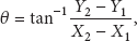
1) Sending a Beacon. It is assumed that every vehicle is equipped with global positioning systems (GPSs). In addition, the vehicle can record its history of movement and current situation. Thus, the vehicle can calculate its speed and direction using (1) and (2)

So, each vehicle can broadcast a beacon containing the information shown in Figure 1.

Beacon message format.
(
2) Receiving a Beacon. Each vehicle receiving a beacon will follow the steps shown below.
According to the vehicle ID information, the vehicle will know if this vehicle exists in its neighbor list or not. If yes, the vehicle will update this neighbor information, and if not, it will add the vehicle to its neighbor list. Based upon the received beacon, the vehicle can predict the location of its neighbor by using (3) and (4)
The vehicle will calculate the link life time (LLT) [23] for its neighbor depending on the predicted location. The vehicle will compare its location with the predicted location of its neighbor to classify it as a member of one of the following groups: same-direction-ahead (SDA), same-direction-behind (SDB), opposite-direction-ahead (ODA), and opposite-direction-behind (ODB). The vehicle will calculate the distance


The prediction process will be continued in the near future. This is based on the previous predicted value, until another beacon comes, so the neighbor's information will be updated and prediction process cycle is started again, or until the vehicle is removed from the neighbor list when its LLT value is smaller than the threshold of LLT value. Anyway, when the vehicle needs to know the location of any other vehicle in its neighbor list, it will use the predicted location value instead of the one initially informed through the beacon.
3.1.2. The Emergency Phase
In the emergency phase, there is an EM to be sent. So, when an accident takes place, the CV will choose the relayer(s), generate an EM, and broadcast it. When a vehicle receives the EM, it will be easy for it to know if it has to do the relay task or not. Whether the vehicle is the first relayer or the second one is decided by the field of the first relayer ID and second relayer ID in the EM format as shown in Figure 2.

Emergency message format.
In this way, the EM will warn the vehicles at the RZ not to have accidents or traffic jams.
In this phase, we have three scenarios for relayer(s) selection.
Scenario 1.
As shown in Figure 3, when the CV wants to select the relayer(s) from its neighbor list, it will perform one of the following steps.
If there is any vehicle behind the CV in the same direction, it will choose the farthest vehicle (FV) as a first relayer (FR), and the second farthest vehicle (SFV) as a second relayer (SR), as shown in Figure 4(a). If there is no vehicle behind the CV in the same direction, but there are vehicles behind it in the opposite direction, it will choose the FV as a FR and the SFV as a SR, as shown in Figure 4(b). If there is no vehicle behind the CV in both directions, but there are vehicles ahead of it in the opposite direction, it will choose the nearest vehicle (NV) as a FR and the second nearest vehicle (SNV) as a SR, as shown in Figure 4(c). If none of the three steps above can be achieved, as shown in Figure 4(d), the CV will store the EM until a new vehicle comes within its transmission range. And it will choose the relayer(s) according to one of the three steps above.
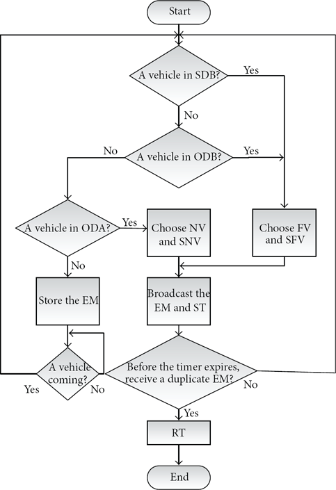
A CV wants to select the relayer(s).
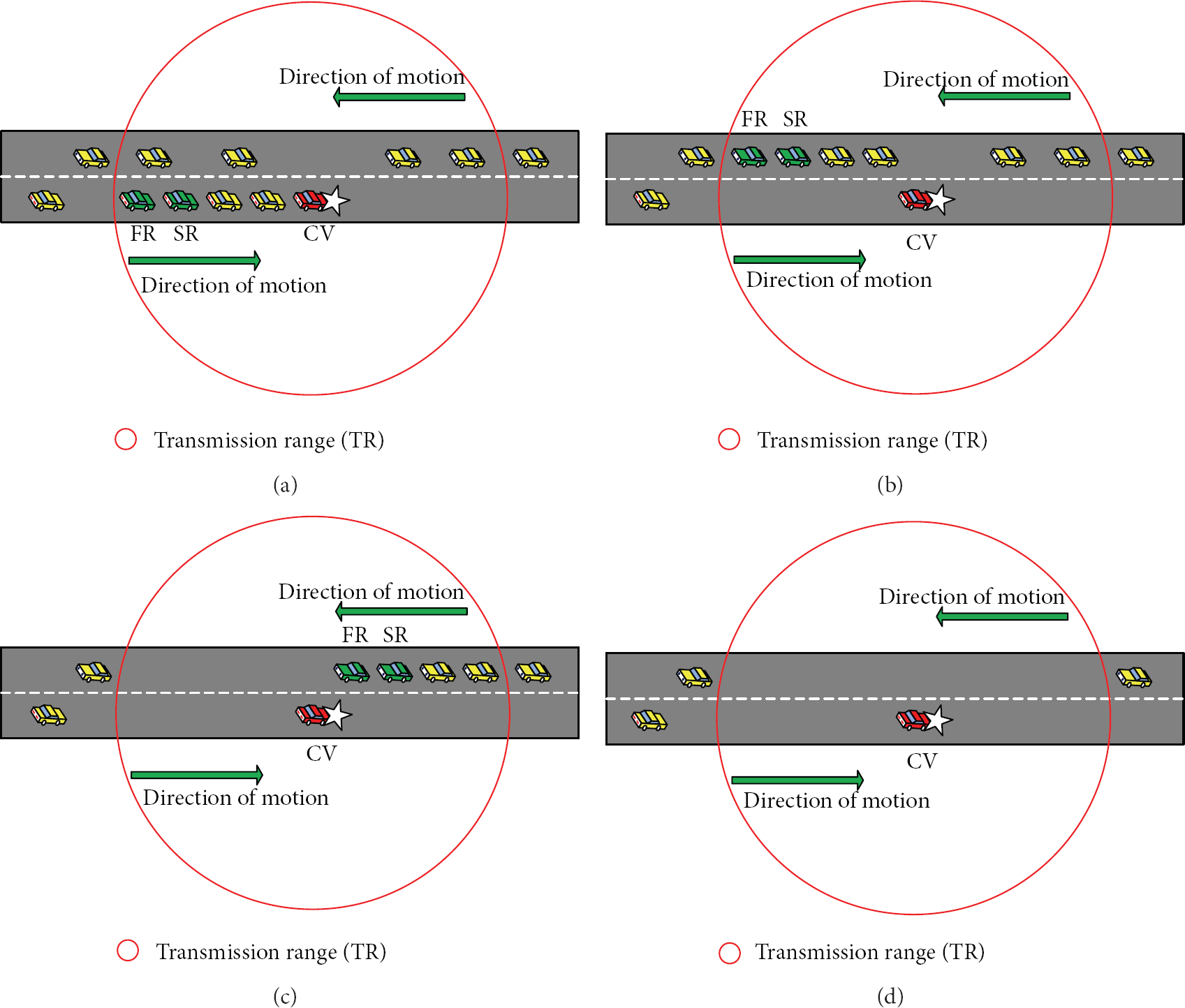
Cases of selecting the relayer(s) by the CV.
After the CV chooses the relayer(s), there will be two possibilities, as will be explained in Scenarios 2 and 3 below.
Scenario 2.
As shown in Figure 5, when the relayer on the same direction of the CV receives the EM, it will check its location. If it is beyond the terminal point (TP) of the RZ, it will do nothing except broadcasting a duplicate EM as an acknowledgment. Otherwise, it selects the best next relayer(s) by performing one of the following steps.
If there is any vehicle behind it in the same direction, it will choose the FV as a first next relayer (FNR) and the SFV as a second next relayer (SNR), as shown in Figure 6(a). If there is no vehicle behind it in the same direction, but there are vehicles behind it in the opposite direction, it will choose the FV as a FNR and the SFV as a SNR, as shown in Figure 6(b). If none of the two steps above can be achieved, as shown in Figure 6(c), the relayer will broadcast a duplicate EM as an acknowledgment and use the store-carry-forward (SCF) mechanism to store the EM in its buffer while checking its location. If it passes by the CV, then it will terminate the forwarding process. Otherwise, whenever it encounters another vehicle within the transmission range which satisfies one of the two steps above, the relayer will choose it as the next relayer and forward the EM to it.

A relayer on the same direction of the CV wants to select the next relayer(s).
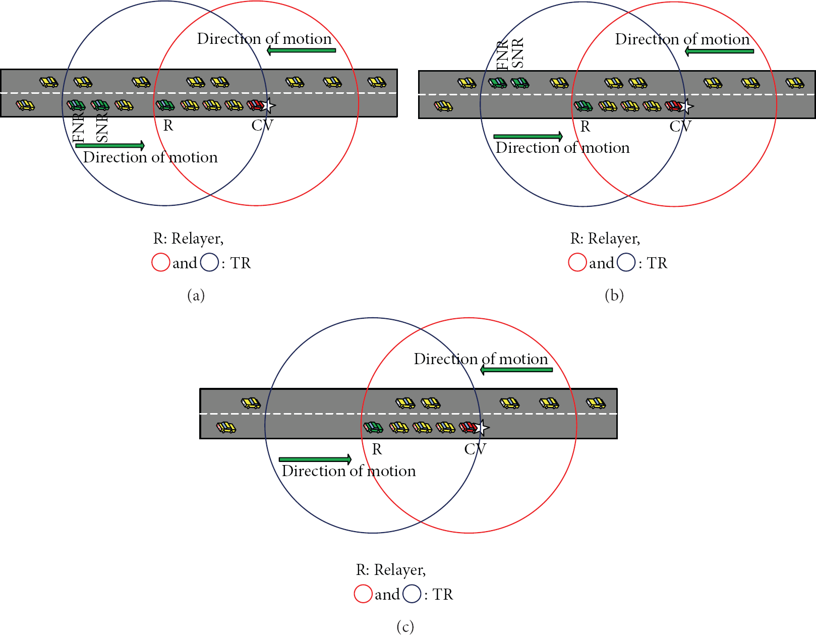
Cases of selecting the next relayer(s) by the relayer on the same direction as the CV.
Scenario 3.
As shown in Figure 7 when the relayer on the opposite direction of the CV receives the EM, it will check its location. If it is beyond the TP of the RZ, it will do nothing except broadcasting a duplicate EM as an acknowledgment. Otherwise, it selects the best next relayer(s) by performing one of the following steps.
If there is any vehicle ahead in its opposite direction, it will choose the FV as a FNR and the SFV as a SNR, as shown in Figure 8(a). If there is no vehicle ahead in its opposite direction, but there are vehicles ahead in the same direction, it will choose the FV as a FNR and the SFV as a SNR, as shown in Figure 8(b). If none of the two steps above can be achieved, as shown in Figure 8(c), the relayer will broadcast a duplicate EM as an acknowledgment and use the SCF mechanism while checking its location. If it passes by the TP of the RZ, it will terminate the forwarding process. Otherwise, whenever it encounters another vehicle within its transmission range that satisfies one of the two steps above, this relayer will choose that vehicle as the next relayer and forward the EM to it.

A relayer on the opposite direction of the CV wants to select the next relayer(s).
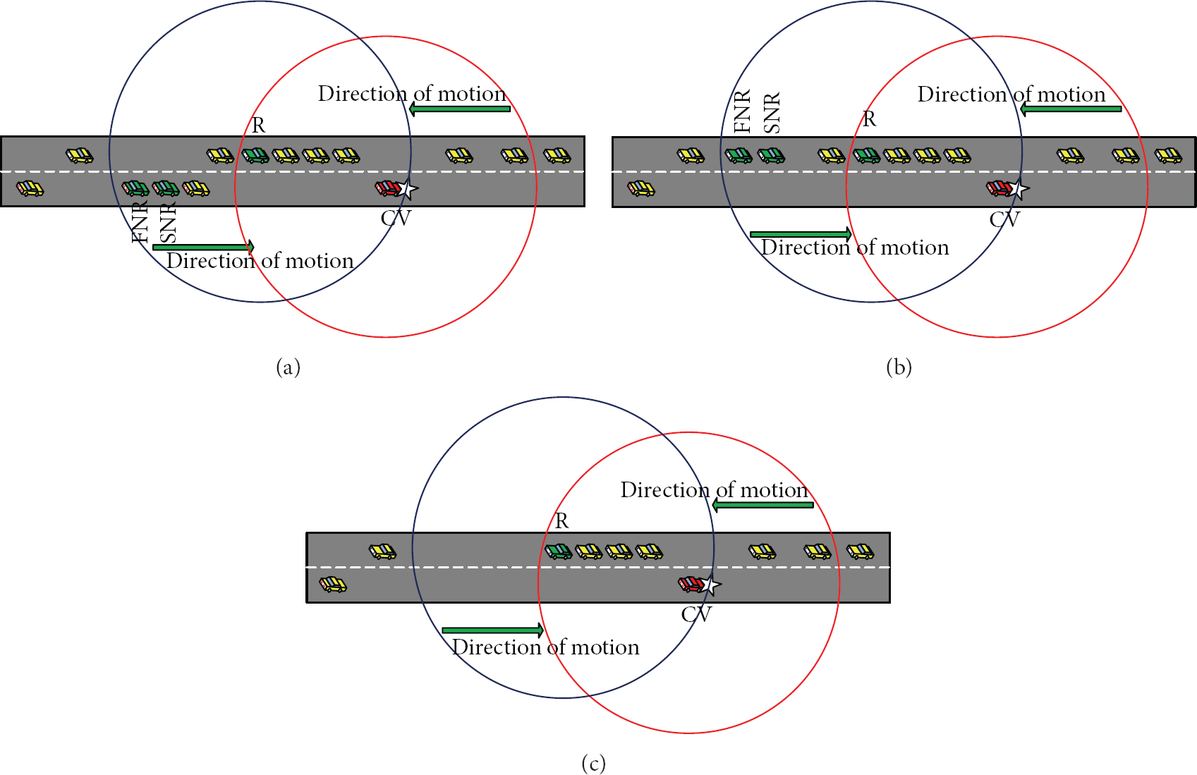
Cases of selecting the next relayer(s) by the relayer on the opposite direction as the CV.
Whenever the relayer or the next relayer receives the EM, it will choose another or other next relayer(s). This selection will be based on the direction of the other next relayer(s) according to Scenario 2 or Scenario 3. But if it does not have any neighbor vehicle(s) in its neighbor list, it has to broadcast a duplicate EM to have the following benefits.
Informing the sender and the second relayer that the message has been received by another vehicle. Thus, they will cancel their rebroadcast task. The vehicles located between the relayer and the sender or between the next relayer and the relayer will receive a duplicate message. Then, if any one of these vehicles were not able to receive this message earlier, it would receive it at this moment.
3.2. The EEMB Scheme Characteristics
3.2.1. Improving the Neighbor's Localization Accuracy
The EEMB scheme reduces the overhead caused by beacons by using the prediction method [24] with some modification. More information such as location, speed, and direction are added to the beacons. This information can be used by vehicles to predict their neighbor's location in the near future, and a vehicle keeps on predicting about its neighbor's location until this neighbor is eliminated from the neighbor list. Also, when the vehicle sends its beacon which includes this information, it will use this information to determine the error between its own predicted location and the real one.
When this error is greater than the threshold of the error predict value, the vehicle itself will broadcast a new beacon that contains the current information in turn leading to updating neighbor's predictions. This method provides a more accurate localization of the vehicle's neighbors through exchanging a smaller number of beacons.
3.2.2. Efficiency Relayer Selection
The use of beacons is important not only for the localization purpose but also for updating the vehicle's neighbor list as well. Thus, a vehicle does not choose a relayer that is not available within its transmission range. So, exchanging beacons of a smaller number by means of prediction may lead to an unreliable neighbor list. A prediction method is suggested to solve this problem by calculating the distance between the vehicle and its neighbor and remove the neighbor which is out of the vehicle's transmission range from the neighbor list. Anyhow, this is not satisfactory for the maintenance of neighbor list. Even if the distance is not greater than the transmission range, but the remaining time of the neighbor in the range is not enough for a forwarding process. This is why the forwarding process fails. Therefore, we use the LLT for this purpose. LLT is the amount of time a vehicle stays within the transmission range of another vehicle.
Each vehicle will calculate the LLT value for its neighbor or neighbors depending on the prediction of location. Those neighbors whose LLT is smaller than the value which is required in the successful forwarding process will be removed from the neighbor list. So, in EEMB scheme, the sender selects the relayer(s) whose LLT value is greater than the threshold of the LLT value. Hence, the use of LLT results in efficient relayer selection and avoidance of message loss or redundancy.
3.2.3. Reliability Increment
After the sender chooses the relayer(s) and broadcasts the EM, it will set a timer (ST) to see whether the relayer(s) receive(s) the EM successfully or not. Consequently, reliability can be achieved by using one of the following two methods: ACK message method and duplicate message method. If the sender receives either of these two from the receiver before its timer gets expired, the sender will reset the timer (RT) and terminate the forwarding process. Otherwise, it will send the EM again. Since most safety applications rely on broadcast fashion, it is not possible to let each vehicle receive the message to send an ACK or a duplicate message to the sender because this will lead to a broadcast storm problem. That is why some schemes handle this problem by making a special vehicle send this ACK message or the duplicate message to the sender [2]. This vehicle is the one selected as a relayer. It should be noticed that what is meant by reliability here is the insurance of the message sent by the sender and received successfully by the relayer. Although both of the two methods mentioned above can achieve this type of reliability, EEMB scheme chooses the second one since it has got other advantages. When the sender broadcasts its message, all the vehicles within its transmission range will receive it, but sometimes, this message may not be received successfully by all these vehicles for one reason or another. The use of the ACK method will not make the vehicles which have not received this message receive it. This method also adds an extra delay because the relayer has to send an ACK message first and rebroadcast the sender's message next. By using the second method, this extra delay is avoided, and at the same time, the probability of making some vehicles which cannot receive the message by the sender's broadcasting receive it instantly by relayer's rebroadcasting is increased.
3.2.4. Redundancy Decrement
Due to the high mobility in VANETs, the location of vehicles is continuously changing. In this case, choosing only one relayer is unsuitable for this type of network. That is why EEMB scheme chooses two relayers. If the first relayer fails to do the relay task immediately, the second one will do it after a period of time almost equal to one-hop delay. During this period of time, if the second relayer receives a duplicate message, it will cancel its forwarding process. When the relayers are located behind the sender, another benefit of choosing two relayers can be obtained: the second relayer will rebroadcast the message if the first one fails and this is better than making the sender broadcast it again since the second relayer will cover more relevant vehicles by its broadcasting than the sender's broadcasting as shown in Figure 9. Thus, the EEMB scheme will reduce the redundancy and increase reliability.

Two relayer selecting procedures.
3.2.5. Overcoming the Network Fragmentation Problem
The density of vehicles varies from place to place and from time to time. Hence, a vehicle may or may not find other vehicles within its transmission range, especially if it takes into consideration only the vehicles moving in the same direction even though the freeway usually has two directions. Consequently, the EEMB scheme takes the advantage of that fact and then the vehicles moving in the opposite direction will be used as relayers if there are no vehicles in the same direction. As a result, the EEMB scheme can overcome the network fragmentation problem when it takes place in the same direction in the network and it reduces the latency caused by waiting till a vehicle in the same direction comes and becomes within the transmission range to forward the message to it. If there are no vehicles moving in both directions, the EEMB scheme will use a SCF mechanism.
4. Simulation and Results
In this section, the vehicular mobility model used in the simulation is introduced. Then, the simulation setup is described. Finally, the results are shown and discussed. A MATLAB (version R2011b) [25] is used to generate the freeway mobility model and evaluate the performance of the proposed scheme, compared with the VANET minimum connected dominating set (V-MCDS) scheme [16], which belongs to the same sender decision schemes.
In the simulation, it is assumed that both the EEMB and V-MCDS schemes work on the same wireless communication environment which is based upon the same wireless communication technologies (e.g., IEEE 802.11 series standards) and have the same lower layer communication characteristics. This simulation is just focusing on the evaluation of the performance achieved by the two schemes.
Compared with the background traffic, the safety data has the highest transmission priority, and the hop delay for safety data is very close to the theoretical value. For the safety data transmission, it looks as though no background traffic is introduced. In the EEMB and V-MCDS schemes, only the chosen relayer(s) will relay the EM. What is more, the occurrence of traffic accident is a matter of moments, and the safety data payload is very small and utilizes a very small proportion of bandwidth thus, the safety data collision is very low and will be omitted in the simulation.
4.1. Vehicular Mobility Model
We have evaluated the EEMB scheme as well as the V-MCDS scheme by comparing the two using the freeway mobility model [26], after making some modification. In this modified model, there are two directions each of which has two lanes. Vehicles are distributed randomly on the freeway lanes in both directions. Each vehicle chooses a random speed which is uniformly distributed in a speed interval
4.2. Simulation Setup
Two aspects of the EEMB scheme are included in the simulation. First, the vehicle moving in the opposite direction is chosen as a relayer if there are no vehicles moving in the same direction. Thus, the EM can be broadcast faster to the relevant vehicles located in the RZ. Second, the prediction method is chosen to reduce the required number of beacon exchanges while improving the neighbor's localization accuracy. To show the efficiency of this scheme, we have compared it with the V-MCDS scheme, which does not include these two aspects. In the V-MCDS scheme, only the farthest vehicle behind and in the same direction will be chosen as the relayer, and the relayer's location will not be predicted, but just gained by exchanging large number of beacons.
The parameters used in this simulation are listed in Table 1. Reference [27] shows that the theoretical number of one-hop delay varies from 1.621 ms to 1.756 ms. Thus, we have taken the average of these two numbers to represent the one-hop delay value. The threshold of error prediction value is set to 25 meters as in [24]. The minimum value allowed for the threshold of the LLT is set to (2*one-hop delay). Clearly, the beacon interval value has an effect on the performance of the schemes. When we made it too big, plenty of out-of-date problems were raised in the V-MCDS scheme, and when we made it too small, the overhead increased in the network due to the high number of beacons exchanged between vehicles. Anyhow, reducing the beacon interval is required to increase the accuracy of localization of neighbors; it is the pursuit of the V-MCDS scheme, since it is unlike EEMB scheme and has not applied the prediction mechanism. That is why, the sound choice for beacons interval value is set to 1 second and 0.5 second for the EEMB and V-MCDS schemes, respectively.
Simulation parameters.

In our simulation, a vehicle will be chosen randomly as a CV at a random time, and the CV must send an EM to the vehicles located in RZ as soon as possible. This can be achieved when the CV chooses the relayer(s) within its transmission range to rebroadcast the EM further. Likewise, this relayer chooses the next relayer(s) within its transmission range and forwards the EM further. As a result, the EM is disseminated from the CV to the other vehicles located in the RZ.
It is assumed that the EM life time is not limited, so in this simulation, the EEMB scheme will continue an EM disseminations until the EM reaches the extreme of the RZ or all vehicles that have been in the RZ pass by the CV. The main aim of our simulation is to make the EM cover the RZ as quickly as possible and hopefully before the vehicles located in RZ pass by the CV with the lower number of beacons exchanged.
4.3. Discussion of Results
Two important metrics have been used to show the efficiency of the EEMB scheme, namely, the risk zone latency (RZL) and the beacon overhead (BCO).
The Risk Zone Latency (RZL). It means the time interval between the EM broadcast by the CV when the accident takes place and when it reaches the extreme of the RZ, or when all vehicles in the RZ pass by the CV.
The Beacon Overhead (BCO). It is the number of beacons exchanged between the vehicles during the simulation time.
Figures 10 and 11 show the average RZL. Each result value represents the average of 120 simulation rounds. As shown in Figure 10 when the traffic density is low, the average RZL in V-MCDS scheme is very high due to the low number of vehicles on the road. Thus, the relayer may not find other vehicles within its transmission range in the same direction behind it, and then, it has to use the SCF mechanism and keeps moving for a period of time known as the disconnecting time until it encounters another vehicle within its transmission range in the same direction behind it. Then, the relayer chooses this vehicle as the next relayer and assigns the forwarding task by rebroadcasting the EM to it. The EEMB scheme takes into account that a network fragmentation problem may take place in the same direction in the network. If there is no vehicle moving in the same direction, it benefits from choosing the vehicle moving in the opposite direction as the next relayer. This approach increases the probability of finding other vehicles, whereas the disconnecting time decreases. As a result, the average RZL in the EEMB scheme is clearly less than that of the V-MCDS scheme, even in the situation of a low traffic density. However, when the traffic density increases, it is likely that the relayer finds other vehicles within its transmission range whether in the same direction or in the opposite one. Thus, the disconnecting time decreases and the average RZL decreases as well.
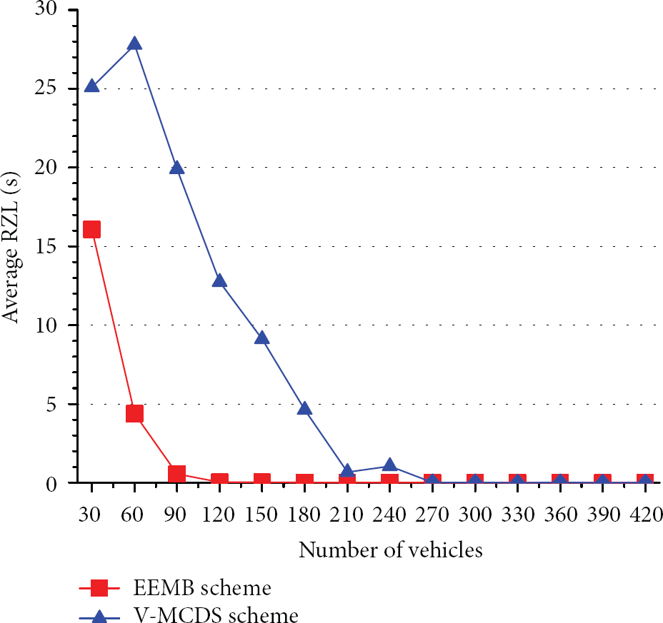
Comparison of average RZL with the number of vehicles at a range from 30 to 420 vehicles in both schemes.

Comparison of average RZL with the number of vehicles at a range from 270 to 420 vehicles in both schemes.
For this reason, the average RZL seems almost equal in both schemes, especially when the number of vehicles is larger than 270. But when taking the magnified sector of the same range as shown in Figure 11, it has been found that the EEMB scheme still has better performance than the V-MCDS scheme with regard to the average RZL, since the possibility of finding a relayer in either of the two directions in the EEMB scheme is greater than finding a relayer just in a single direction as in the V-MCDS scheme.
Figure 12 shows the comparison of the total number of beacons exchanged between the vehicles during the simulation time. According to this figure, the V-MCDS scheme has a huge number of beacons exchanged. First, a shorter beacon interval is required to reduce the out-of-date problem. Second, the V-MCDS scheme makes a vehicle send a new beacon when it changes its state (i.e., speed or direction) and any vehicle receives this beacon will in turn send a new beacon. Therefore, the BCO will increase when the number of vehicles increases (dense network), when the beacon interval decreases, and when the vehicle changes its state rapidly.
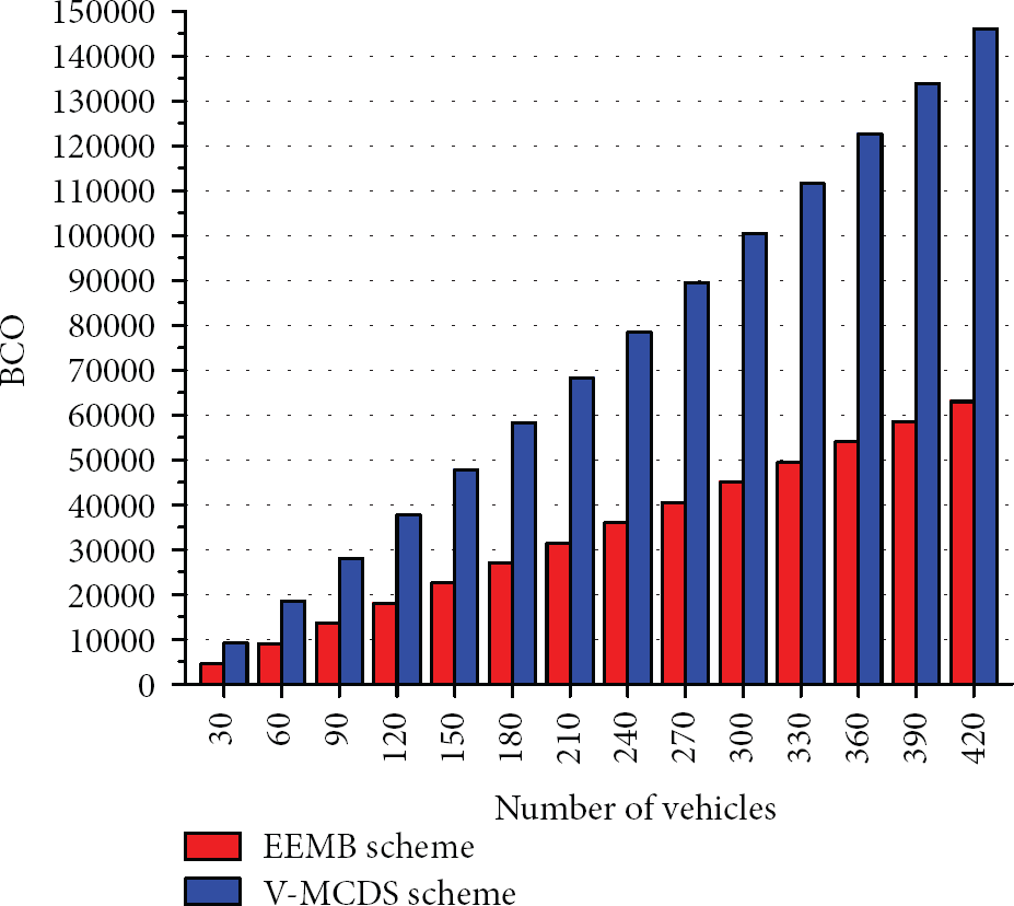
The number of beacons in both schemes.
In the EEMB scheme, the BCO is smaller than that of the V-MCDS scheme, because first, through prediction, beacons exchange at a lower rate, so beacon interval increases, and second, when the vehicle changes its state, it will not send a beacon immediately, but it will send it when the difference between its predicted location and its real one becomes greater than the threshold of error predict value, and each vehicle receiving this beacon is not required to send a beacon. Thus, the number of beacons that need to be exchanged between the vehicles is reduced. As a result, the BCO of EEMB scheme during the simulation time is clearly less than half of V-MCDS scheme as shown in Figure 13.

Ratio of the number of EEMB scheme beacons to the number of V-MCDS scheme beacons.
5. Conclusions
In this paper, we have proposed an EEMB scheme to broadcast EM to the relevant vehicles located in the RZ in order to avoid further accidents or to reduce the traffic jams. When an accident takes place on the road, the CV chooses two relayers among its neighbors and then it generates and broadcasts an EM. If the first relayer fails to rebroadcast the EM, then the second one will do that and the relayer will, in turn, choose the next relayer(s) and rebroadcast the EM until the EM covers the whole RZ. The network fragmentation problem is a real issue in VANETs, especially in the sparse network. The EEMB scheme overcomes this problem through the use of vehicles that are moving in the opposite direction to be chosen as the relayers when there are no vehicles in the same direction. An SCF mechanism has been used when there are no vehicles moving in both directions. Our scheme has also addressed the problem of beacon overhead by using the prediction method which adds more information to beacon messages. Therefore, the vehicles can use this information to predict their one-hop neighbor's location in the near future, thus providing a more accurate localization of the neighbor's location by exchanging a smaller number of beacons. In the simulation, we have compared the EEMB scheme with the V-MCDS scheme through two important metrics of EM broadcasting in safety applications. These metrics are RZL and BCO. The simulation results show that the EEMB scheme has better performance than the V-MCDS scheme in terms of these two metrics.
Footnotes
Acknowledgment
This work was supported by the National Natural Science Foundation of China (NSFC) (Grant no. 61103177).