
Abstract
A thermoelectric energy harvester powered wireless sensor networks (WSNs) module designed for building energy management (BEM) applications is built and tested in this work. An analytic thermoelectric generator (TEG) electrical model is built and verified based on parameters given in manufacturer data sheets of Bismuth Telluride TEGs. A charge pump/switching regulator two-stage ultra-low voltage step-up DC/DC converter design is presented in this work to boost the <0.5 V output voltage of TEG to usable voltage level for WSN (3.3 V). The design concept, device simulation, circuits schematic, and the measurement results are presented in detail. The prototype device test results show 25% end-to-end conversion efficiency in a wide range of input temperatures/voltages. Further tests demonstrate that the proposed thermoelectric generator design can effectively power WSN module which operates with a 1.7% duty cycle (5.8 seconds measurement time interval) when the prototype is placed on a typical wall-mount heater (60°C surface temperature). The thermoelectric energy harvesting powered WSN demonstrates duty cycles significantly higher than the required duty cycle for BEM WSN applications.
1. Introduction
Ubiquitous computing and short range wireless communication have been developing rapidly since 1990s. Evolving from basic point-to-point radio frequency communication, wireless communication technology now provides reliable data links within ad hoc networks. In the similar period of time, the developments of advanced and low cost sensors significantly increase the applications of modern sensing systems. The combination of wireless communication and sensor technologies has made it possible to transform the conventional large scale monitoring equipment into smart wireless sensor node within ad hoc networks.
Wireless sensor networks (WSNs) technologies have become a research focus in recent years for wide range of applications. One important application of WSN is within the building energy management (BEM) area. Energy consumption of commercial and residential buildings is responsible for 40% of energy usage in the USA since mid-2000s [1]. Many have suggested that the utilization of building energy management systems potentially leads to 25–40% energy savings from smart control of heating, ventilation, air conditioning (HVAC), and lighting [2–4]. Applications of WSN for building energy management system have been addressed in [5–8].
In these studies, one issue that has been frequently discussed for BEM WSN development is the limited lifetime of wireless sensor modules (also known as “mote”) due to battery energy capacity. With increased number of motes in the WSN, the mandatory requirement to replace battery for several hundreds even thousands of WSN motes significantly increases the maintenance cost and reduces system reliability.
Energy harvesting methods have been proposed to scavenge ambient energy in order to “self-power” WSN systems. Energy harvesting technologies present a solution to supply WSN mote with infinite ambient energy instead of locally stored battery energy. Various types of ambient energy sources have been proposed for energy harvesting, such as indoor and outdoor photovoltaic energy [9, 10], mechanical vibration energy [11, 12], and thermoelectric energy [13–16].
In BEM applications, a large number of heating devices in the HVAC units, boiler, water heaters, and hot water pipes exist in most commercial/residential buildings. These potential heat sources with 50–100°C temperature provide ideal energy sources for building energy monitoring systems.
Utilization of these thermoelectric energy sources may lead to the highly desired “deploy-and-forget” WSN; that is, once the energy harvesting powered mote is deployed onto the heat source, the WSN becomes self-powered and achieves power autonomy. However, the implementation of thermoelectrical energy harvesting in order to achieve the continuous and maintenance-free WSN mote operation is significantly constrained by the ultra-low voltage (less than 0.5 V), small power (1 mW or sub-1 mW), and device size limitation of thermoelectric generator (TEG).
Despite these challenges, thermoelectric energy harvesting technologies are developing at fast speed in recent years. Many works addressed the high ZT figure of merit thermoelectric generator using MEMS or nanotechnology fabrication processes [17–19]. Ultra-low voltage DC/DC converter for thermoelectric generator applications has also been proposed in [14, 16]. However, thermoelectric energy harvester system level design for wireless sensor module is an area less addressed. Although the thermoelectric energy harvester systems presented in [20–22] give a well-defined general review and analysis, these works lack the important details on power management circuit design and components selection.
The purpose of this paper is to demonstrate a practical methodology concerning the thermoelectric energy harvester design for WSN mote in real-world BEM applications. This method firstly characterizes the power consumption profile of WSN mote. The thermoelectric energy harvester model is then used to estimate the TEG device size and configurations for the WSN power consumption. Associated power management circuit is then designed towards high conversion efficiency with TEG configuration. This methodology builds and optimizes energy harvester based on real-world WSN mote power consumption. This application-oriented design concept incorporates more realistic design considerations when the device is deployed in real-world conditions.
This paper introduces a thermoelectric generator electrical characteristics model for low temperature applications (hot side temperature <100°C, cold side temperature is room temperature with passive heat sink cooling) and its results verification based on a custom manufactured Bismuth Telluride (
The main contribution of this paper lays in the power management circuit design for ultra-low voltage DC/DC conversion: a two-stage DC/DC converter circuit with ultra-low start-up voltage charge pump and switched-mode boost converter is proposed to step up the minimal 250 mV TEG voltage output. The detailed circuit design and components selection are presented. Energy storage unit and associated output power regulator circuit are introduced to complete the thermoelectric energy harvester design. The power consumption of Tyndall Zigbee WSN mote is also presented and compared to the power generated from thermoelectric energy harvester. Finally, the thermoelectric energy harvesting powered WSN prototype device and its evaluation results are presented. The energy flow and conversion efficiency in each stage of power conversion are presented based on measurements made on the prototype.
The rest of the paper is organized as follows. In Section 2, background and related works in the area of thermoelectric energy harvesting are introduced and compared. Section 3 shows the proposed system architecture of thermoelectric energy harvester. Section 4 addresses the detailed design issues of thermoelectric energy harvesting powered WSN mote system. Section 4.1 presents the energy consumption of WSN mote designed in Tyndall and its typical power profile. Section 4.2 shows the proposed TEG simulation model for room temperature applications and its verifications. Section 4.3 discusses the power management circuits design and implementation. Section 4.3 also introduces the energy storage unit and the output power regulator circuits. Section 5 presents the TEG prototype device and the experimental results. Section 6 summarizes the conclusions of this paper.
2. Background and Related Works
Thermoelectric energy harvesting is based on the Seebeck effect which directly converts temperature difference into electricity. The structure of a typical vertical TEG module is illustrated in Figure 1. When a temperature difference is applied cross the P-N types of TEG couples, voltage potential is generated on the the TEG couple. The thermoelectric material performance is usually measured in thermoelectric figure of merit ZT [13].

Seebeck effect in thermoelectric energy harvesting.
Currently, a typical “high” energy conversion efficiency commercially off-the-shelf TEG module features a ZT around 0.6-0.7 in room temperature. This was achieved by
Designated for powering miniaturized wireless sensor nodes, the TEG module and its heat sink are inherently small in form factor. The temperature difference available on a conventional heat sink in such condition is also small (<10°C from a <100°C heat source). With relatively low temperature difference and limited thermocouples size, further power conditioning is essential to the energy harvesting system design.
Dalola et al. presented a TEG powered sensor and transmitter circuit in their paper [25]. Charge pump converter is used as the only DC/DC conversion circuit. Ramadass and Chandrakasan proposed an advanced thermoelectric power management solution [26]. A DC/DC converter with minimum start-up voltage at 35 mV is designed and implemented with a 0.13 μm CMOS process. A manual controlled switch is required to start up the DC/DC converter. Carlson et al. demonstrates a 20 mV start-up voltage DC/DC converter in [14]. Although this DC/DC converter achieves a 75% maximum converter efficiency, it requires an external voltage source to initialize the start-up circuit.
Linear Technology released an energy harvesting power management chip LTC3108 [27]. It achieves top efficiency at 40% using a 1 : 100 transformer setup. However, for input voltage at 0.2 V or higher, the conversion efficiency decreases to less than 10% when output voltage is set to 4.5 V (1 : 100 transformer setup). Texas Instruments also released an energy harvesting power management chip BQ25504 for thermoelectric energy harvesting [28]. It features a minimal start-up voltage of 40 mV. BQ25504 requires a start-up current of several mA in order to obtain 1.8 V power supply voltage on the storage capacitor. During this start-up phase, this converter operates in cold start mode with low conversion efficiency. For many 1 mW or sub-1 mW energy harvesting applications, it is possible that the harvested power in the cold start phase is not sufficient to charge the storage capacitor to its required voltage threshold, which potentially leads to unsuccessful start-up, and the system cannot enter the normal operation mode.
3. Thermoelectric Energy Harvesting Powered WSN System Architecture
A complete thermoelectric energy harvesting powered WSN system consists of five subsystems as shown in Figure 2.
Thermoelectric generator (TEG): main design issues are type of material, number, size, and connection configuration of thermocouples. Ultra-low voltage step-up DC/DC converter: the output voltage of most of TEGs is less than 500 mV. Conventional boost converter and charge pump cannot provide the low start-up voltage required by the TEGs. DC/DC converter with lower minimal start-up voltage is essential for thermoelectric energy harvesting. Energy storage unit: the conventional rechargeable battery, which requires relatively complex charging circuit and has a limited lifetime and charge cycles, is not suitable for most low power energy harvesting applications. Electrical double layer capacitors (also known as supercapacitors or SuperCaps), which only require a simple charging circuitry and have a long operation lifetime (>10 years), are considered to be the preferred energy storage unit (ESU) in energy harvesting. Output power regulation: output voltage regulator is used to extract “usable” energy from energy storage unit. For SuperCap type ESU with a changeable output voltage, the output power regulation is important to obtain a constant voltage to the WSN mote. In addition, with a buck-boost converter topology, the output voltage regulator also increases the amount of stored energy that can be used for WSN mote. WSN mote: the energy harvester design is largely based on the power consumption and other electrical characteristics of WSN mote. The power consumption analysis of WSN mote is an essential step before energy harvester design.
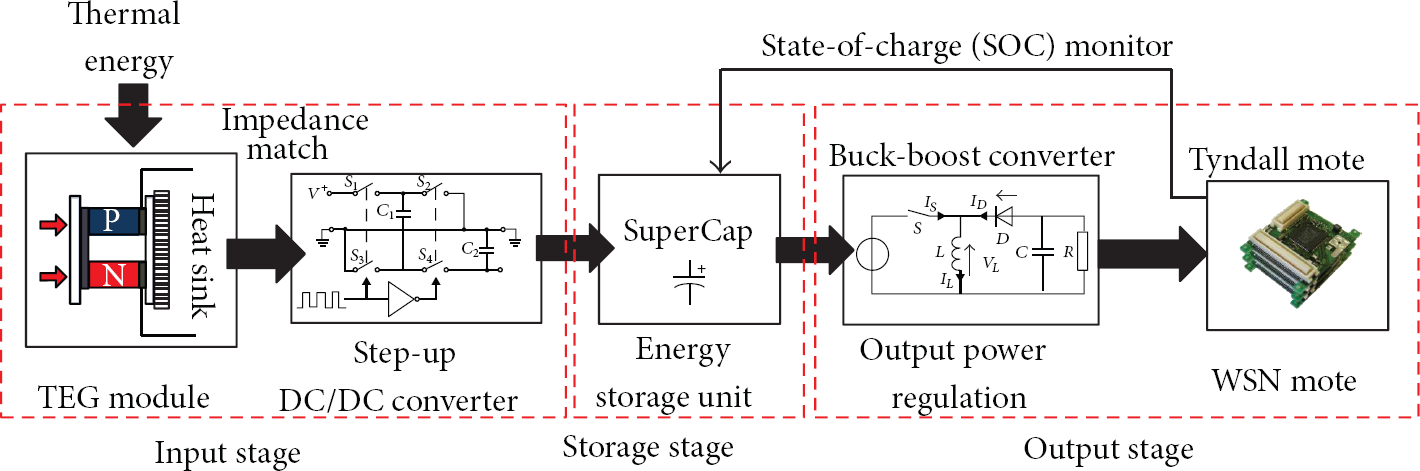
Block diagram of thermoelectric energy harvesting powered wireless sensor network.
In addition, these building blocks of thermoelectric energy harvester are not isolated components but inter-related subsystems. Several design considerations and challenges need to be addressed in the practical design and implementation of thermoelectric energy harvesting powered mote.
The energy equilibrium between mote power consumption and thermoelectric energy harvester power generation must be achieved to ensure a continuously operating WSN mote. The impedance matching between TEG and DC/DC conversion has direct impact on the system power conversion efficiency. The energy storage unit and power consumption of WSN mote will determine the lifetime of mote when thermal energy source is temporarily unavailable.
Detailed design and analysis of each subsystem and the relationships between the aforementioned subsystems are presented in the following sections.
4. Design and Optimization of Thermoelectric Energy Harvesting Powered WSN Mote
4.1. Power Consumption of Wireless Sensor Module
A typical wireless sensor network for BEM applications consists of a number of wireless sensor nodes (motes). For each mote, it normally features (1) microcontroller unit (MCU); (2) wireless communication unit; (3) sensors with digital/analog interfaces; and (4) power supply.
The Tyndall mote [29] layout and implementation for BEM application is shown in Figure 3. The sensor interfaces are

Wireless sensor node for building energy management application [23].
WSN mote features high power consumption (10–100 mW) in active mode and low power consumption in sleep mode (10–50 μW). Thus, WSN mote often operates in active/sleep duty cycles in order to reduce average power consumption. During operating cycles, each mode of operation has an intrinsic power consumption value. The main operating modes are
initialization and clear channel assessment (CCA) mode, sensing mode (sensors are active and being sampled through the ADC), preamble and payload Tx (RF transmit) mode, acknowledgement (ACK) Rx (receiving) mode, and sleep mode.
In addition to the power consumption profile, the average power consumption of the WSN mote is also determined by the active mode duty cycle D. The average power consumption

The power consumption values for the Tyndall mote shown in Figure 4 are listed in Table 1.
The power consumption of a Tyndall BEM mote at 3.3 V (sleep mode is 300 seconds, that is, 5-minute measurement interval).


Measured current consumption of main operating modes (Tyndall WSN mote, Tx transmitting power = 0 dBm).
In order for a WSN mote to operate indefinitely, the average power consumption needs to be lower than the average harvested power, and this can be controlled by adjusting the duty cycle(s), D, of the application. Furthermore, the capacity of the power source (battery or supercapacitor) needs to be large enough to support peak power consumption, for example, the power consumption during RF transmission.
Based on the power consumption and duty cycle characteristics of WSN mote, thermoelectric energy harvester is designed for Tyndall mote to achieve power autonomy with large duty cycle.
4.2. Thermoelectric Generator Module Design and Electrical Model
The basic thermoelectric effect, Seebeck effect, describes a phenomenon that generates voltage difference when temperature gradient is applied across two series connected dissimilar materials as shown in Figure 1. The equivalent circuit for the thermoelectric voltage generation is illustrated in Figure 5.

Basic equivalent circuit of thermoelectric generator.
The voltage generated from the single TEG pair is


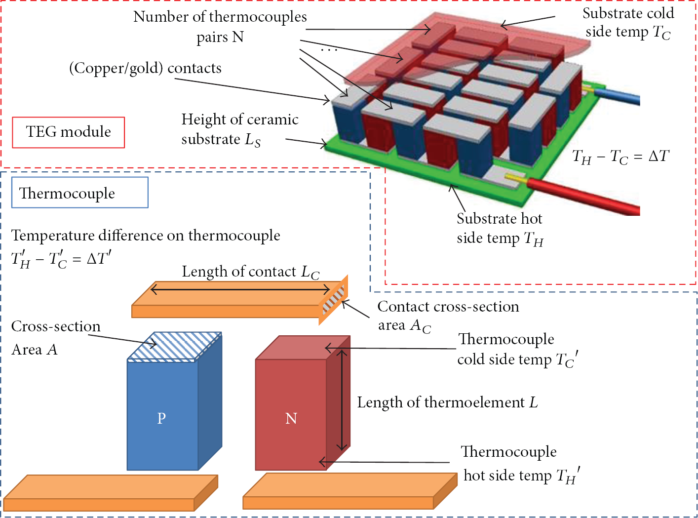
Thermoelectric generator (TEG) module and thermo-couple structures.
A typical TEG module [30] with precision machined thermo-couples is shown in Figure 7.

Thermoelectric generator layout, thermo-couple and thermoelectric module pictures.
The
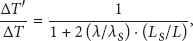
The temperature difference across the thermo-couples is illustrated in Figure 8. The actual temperature difference on the thermo-couples is expressed as
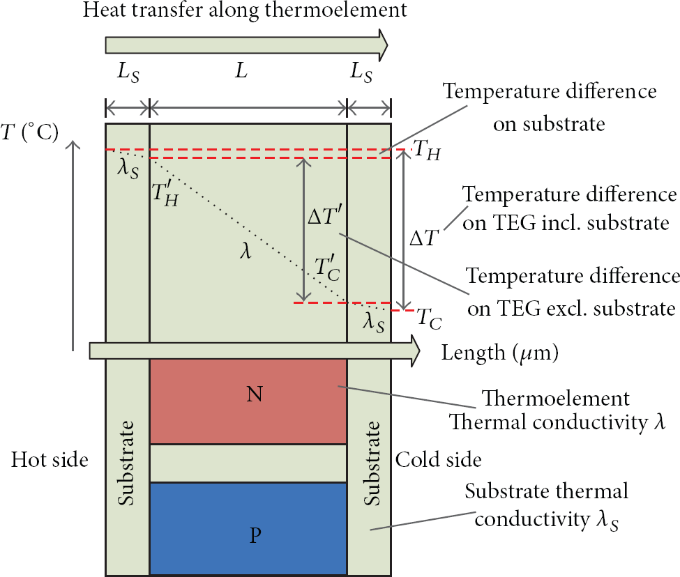
Heat transfer within thermoelectric generator.
Based on this heat transfer model and temperature difference 
With increased number of thermo-couples, the internal resistance R also increases due to series connection of large number of thermo-couples and copper contacts. The resistance of the TEG module with N pairs of thermo-couples is shown as

The thermoelectric module used to verify this model is provided by thermonamic [30]. This TEG module is a custom-designed module for low power generation. It adopts
Conventional machined thermoelectric module parameters summary.

A series of tests were conducted in order to verify this analytic electrical simulation model. The test setup is illustrated in Figure 9. The heat source is a temperature controlled hot plate. The TEG module is cooled by a passive “fin” type heat sink. A PicoTech ADC-11/12 data acquisition system is set up to monitor the temperature on the outer side of upper/lower substrates by using PT-100 temperature sensors. The I-V characteristics of the TEG module are measured by oscilloscopes and multimeters.

Thermoelectric generator electrical characterizations test configuration.
The room temperature during the experiments is approximately 20°C. Four hot side temperatures are applied, 50°C, 60°C, 70°C, and 80°C. The measured I-V characteristics of thermonamic TEG module are shown in Figure 10. The measured power-voltage characteristics are illustrated in Figure 11.

Measured I-V (current-voltage) characteristics of thermonamic TEG module.

Measured power-voltage characteristics of thermonamic TEG module.
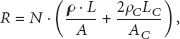
The load resistance tested in the characterization is between 1 Ω and 1 KΩ. The maximum power is obtained when the load resistance is 8.5 Ω. The analytic model and the measured results are compared in Table 3. The simulation in the thermonamic TEG shows a high level of consistency with the measured TEG electrical characteristics. The power simulation errors are less than 5% of the measurement values.
Thermonamic TEG characterizations results and simulation results at matched load.
This analytic model is then realized in MatLab and used to simulate the output voltage and power in this work. It is also used to calculate the internal resistance of TEG.
4.3. Thermoelectric Energy Harvesting Power Management Circuit Design and Implementation
From the device characterization, one main issue discovered for thermoelectric energy harvesting is that the voltage of the TEG output is one order of magnitude lower than the WSN operating voltage. A voltage step-up circuit is required to boost the 100–500 mV input voltage to 2.5–4.5 V output voltage. This problem leads to two types of proposed power management methods, the first one uses ultra-low voltage boost converter with a large conversion ratio transformer; the second method uses low voltage charge pump and boost converter, a two-stage step-up design.
As introduced in [14], ultra-low voltage boost converter with a transformer conversion ratio 1 : 100 can step up input voltage as low as 20 mV to 2.0–4.5 V. The main concern in this type of design is the inherent low conversion efficiency for high ratio voltage step up.
This work adopts the second type of DC/DC conversion, the low voltage charge pump and boost converter two-stage step-up design. The start-up DC/DC converter is a Seiko Instruments S882Z-18 ultra-low voltage charge pump with a minimal start-up voltage at 0.25 V–0.3 V. The main DC/DC converter is Texas Instruments TPS61020 with a 0.9 V minimal start-up voltage.
In addition to the multiple stage power conversion, impedance matching is also considered in this design. Previous study confirmed that
Changes on the duty cycle of the boost converter can effectively adjust the input resistance of the power management module. By matching the input resistance of power management circuit

TEG and power management circuit impedance matching.
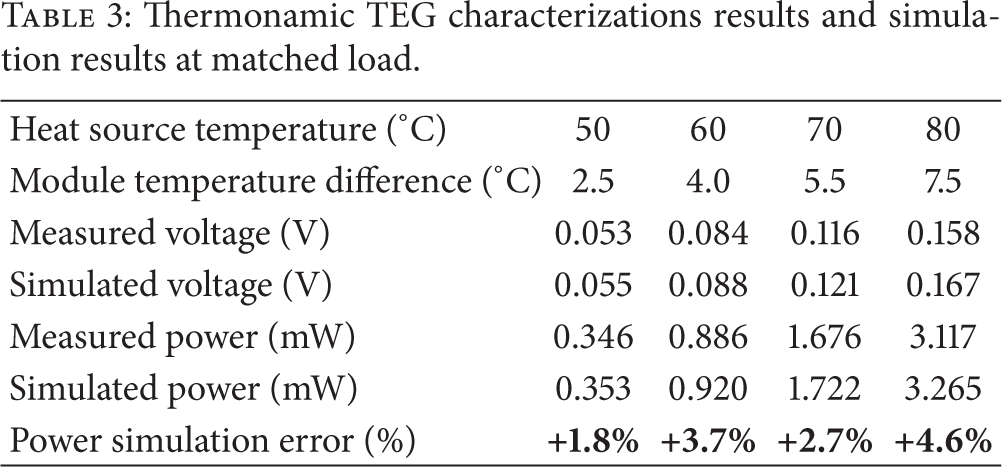
Another design issue related to the thermoelectric energy harvesting power management is the energy storage unit and its output power regulation. In this work, supercapacitor is used as the energy storage unit. The porous structure of electrode material in supercapacitor effectively separated by electrochemical property of the electrolyte instead of thick physical dielectric layer ensures a large capacitance of several Farads. However, one issues that has not been fully addressed in the previous literature is the leakage current of supercapacitor. Due to the small power consumption of WSN mote, the 10–100 μA level leakage current is no longer negligible.
To investigate the leakage current characteristics, self-discharge tests were conducted on 4 different supercapacitors (Table 4). All the super-capacitors were precharged to the same voltage level. They were then isolated, and the voltage drops were monitored periodically by using a Pico Technologies ADC-11/12 data acquisition device. The data acquisition device has an output end impedance of 1 MΩ during measurements and a 10 MΩ impedance in idle mode, which effectively eliminated the current flow through the probe. The voltage drop is therefore only related to the self-discharge of the super-capacitors. The 24-hour results of the self-discharge tests are presented in Figure 13.
Supercapacitor average leakage current and leakage correlation

Supercapacitors self-discharge test over 24 hours. (Conditions: room temperature: 10°C; all samples have been fully charged and discharged for 100 times before the test.)
These results confirm that the self-discharge rates (SDR) of the super-capacitors are considerably higher than those of rechargeable batteries (5–10% monthly self-discharge rate). The super-capacitors have SDR ranging from 45% to 15% every 24 hours. Therefore, without an intermittently available energy source every few days, using the super-capacitors alone as a long-term storage solution is not feasible.
I-V characterizations were conducted to investigate the input resistance
Based on these measurement results, a near linear correlation is found between leakage current
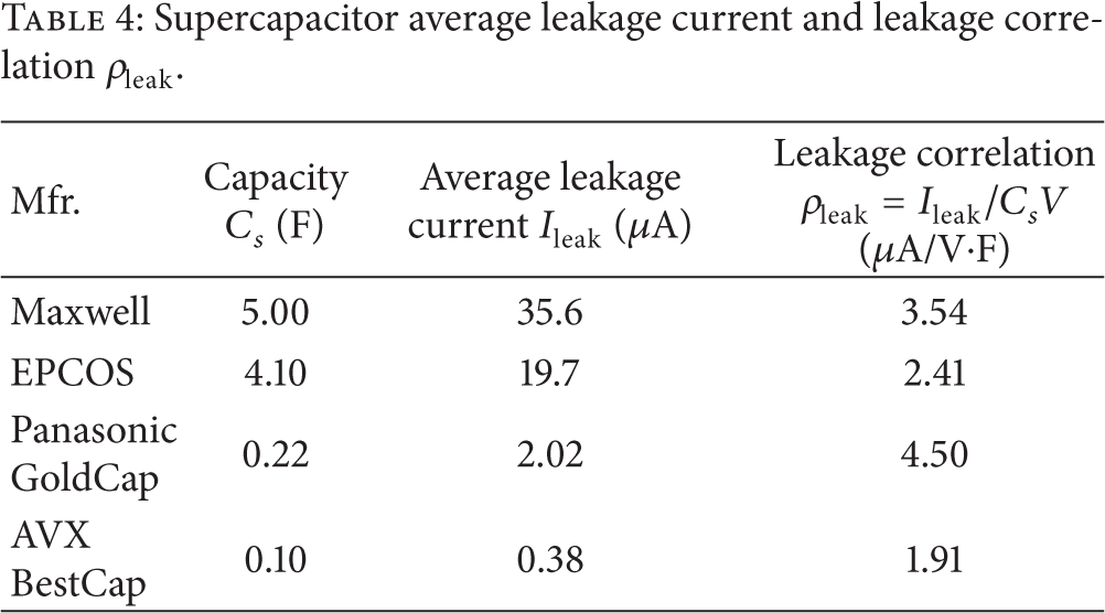
Based on these design considerations, the complete schematic of the thermoelectric energy harvester is shown in Figure 14.
Schematic of thermoelectric energy harvester.
In order to extract most of the energy from the super-capacitor, a buck-boost converter Texas Instruments TPS61220 is used for the output voltage regulator. The input voltage range is between 0.7 V and 5.5 V. The output voltage is programmed to 3.3 V for Tyndall WSN mote. The detailed component selection and value are given in Table 5.
Component selection for thermoelectric energy harvester.

In this work a super-capacitor array
The results of the characterization are shown in Figure 15.

Thermoelectric energy harvester power management module input resistance and TEG internal resistance impedance matching.
For input voltage (TEG output voltage) between 0.25 V and 0.7 V, the input resistance
For 2 parallel-connected 288 thermo-couple pairs,
Figure 16 shows the TEG module output voltage simulation based on the analytic model. The simulation results show that for 2 parallel-connected 288 thermo-couple pairs configuration, the TEG output voltage is between 280 mV and 450 mV when the temperature difference on the substrates is 3–5°C. This output voltage is higher than the minimal start-up voltage of the charge pump and can start up the charge pump and the other circuits in the power management module.

TEG module output voltage simulation.
5. Thermoelectric Energy Harvester Implementation and Experimental Results
Based on the proposed TEG module and power management circuit design, the device manufacturing and assembling were conducted. Four thermonamic TEG modules are used to assemble the TEG module into 288 × 2 thermo-couple configuration. The complete prototype is shown in Figure 17. The form factor of the thermoelectric energy harvester powered WSN mote is 6 cm (L) × 5 cm (W) × 7 cm (H).

Thermoelectric energy harverting and power management module prototype for BEM applications.
The prototype design also took the thermal dissipation on the PCB layer into consideration. The heat sink of the TEG is fastened to the PCB through a set of four long screws. This configuration allows typical indoor airflow to further cooling of the heat sink and generates higher temperature difference.
The viability of the TEG design and the application on WSN were tested through a set of experiments. The prototype was placed on hotplate in various temperatures to test the start-up performance, continuous operation efficiency, and energy storage charge time. The experiment result of the TEG start up at 60°C is shown in Figure 18.

Thermoelectric energy harvester start-up test results.
The charge pump S882-Z starts at 0.25–0.3 V, and the voltage on storage capacitor of charge pump
At 60°C hot side temperature, when the energy harvester reaches thermal static state, the output voltage of TEG module is measured at 0.25 V as shown in Figure 18. The open circuit voltage of TEG before power regulation is at 0.47 V. The output voltage 0.25 V is close to the theoretical maximum power point at half of open circuit voltage 0.235 V (0.47 V × 0.5). This proves the concept of impedance matching between the TEG source resistance and the input resistance of power management proposed in this work.
Further tests were conducted to investigate the conversion efficiency of this proposed thermoelectric energy harvester. The I-V characterization of the TEG module output power and the step-up DC/DC converter output power are presented in Figure 19.

I-V characterization of the TEG module output power and the step-up DC/DC converter output power (hot side temperature 60°C).
Figure 20 shows the power-voltage characterizations of TEG output power and the step-up DC/DC converter output power. The matched load TEG maximum output power is measured at 4.08 mW. The output power of step up DC/DC converter (charge pump and switching regulator) thermoelectric energy harvester is measured at 1.1 mW.

Power-voltage characterizations of the TEG module output power and step-up DC/DC converter output power (hot side temperature 60°C).
Table 6 summarizes the energy transfer in the power management circuit when the hot side temperature is 60°C. With a 28.9% conversion efficiency, most of the power loss is due to the conversion energy loss in the ultra-low voltage charge pump. Both the boost converter (second stage of the step-up DC/DC conversion) and buck/boost converter (output voltage regulator) achieved conversion efficiency higher than 90%. The system end-to-end conversion efficiency is 25.2%.
TEG power management energy transfer.

It is worth noting that the super-capacitor(s) are not considered in this conversion efficiency summary. The thermoelectric energy harvester performance with super-capacitors is characterized separately. The super-capacitor charging results from 3 difference hot side temperatures are presented in Figure 21.

Thermoelectric energy harvester prototype charging.
When charging the capacitive load, the average charging power 
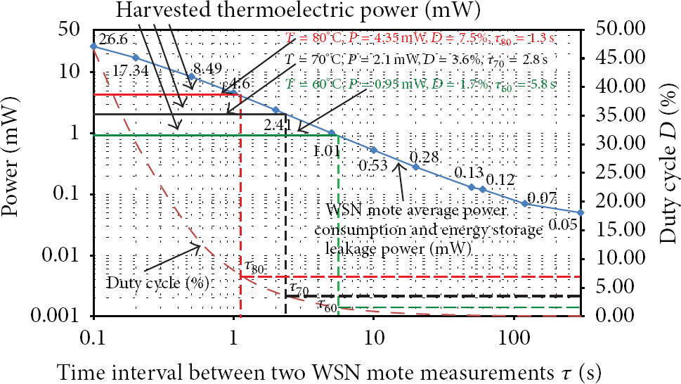
The thermoelectric energy harvester performance with WSN mote is then evaluated based on WSN power consumption and energy storage leakage power consumption. WSN mote can be programmed with different time intervals τ between two measurements (active mode). Since the active mode time 
Thermoelectric energy harvester prototype charging supercapacitor.
For 60°C hot side temperature, the minimal measurement time interval is 5.8 seconds; that is, when placing the thermoelectric energy harvester on a 60°C heat source, the generated power allows WSN mote to make a BEM measurement and transmit the data every 5.8 seconds. For higher hot side temperatures, the minimal measurement time intervals are shorter. Most BEM applications (light intensity, temperature, relative humidity, etc.) require measurements time interval between 1 and 10 minutes. The thermoelectric energy harvester proposed in this work can effectively provide a “power-autonomous” power supply for BEM WSN motes when thermal energy is available.
When compared with recent work in the thermoelectric energy harvesting, this bulk TEG based thermoelectric energy harvester proposed in this work achieved the self-start capability suggested in [35] and can be deployed for long-term operation. The TEG generated power is measured at 0.95 mW with a 4°C temperature difference in this work, whilst in [35], 0.2 mW is generated with a 3.5°C temperature difference. In addition to the higher output power, the bulk TEG can be manufactured at lower cost than the MEMS TEG utilized in [35].
6. Conclusion
In this paper, low temperature thermoelectric energy harvester is investigated for the use of powering wireless sensor network. The main focus is on the energy conversion efficiency improvement from the prospective of power management and TEG design. This study characterized the
Based on the characterizations and the simulation of the TEGs, power management circuits with emphasis on low voltage step up are investigated in the second half of this paper. In order to obtain a regulated output voltage from the less than 0.5 V low input voltage, multiple-stages voltage regulation is considered in this work. The power management adopted the charge pump/switching regulator two stages design to obtain lower conversion ratio on each stage. The charge pump starts up the voltage regulation when the TEG voltage is higher than 250 mV, whilst the boost converter starts up at 0.95 V.
It has been noticed that by adjusting the configurations of TEG, the source resistance and output voltage can be modified to match the power management circuit input impedance. Based on this method, the TEG was re-configured based on the analytic simulation model with a 9.9 Ω source resistance, whilst the power management circuit input resistance is matched with the source resistance with less than 10% error (0.25 V–0.38 V input voltage). The device implementation consists of two 160 thermo-couple pairs TEG modules configured in the parallel-connected layout. At 60°C, the output voltage of TEG (input voltage of power management) is measured at 0.25 V, close to the 0.235 V maximum power voltage (half of the open circuit voltage 0.47 V).
Although the charge pump runs in a relatively low conversion efficiency of 28–30%, the high conversion efficiency (approximately 93%) of the second stage voltage regulator TPS61020 (from 1.0 V to 3.3 V) and output voltage regulator TPS61220 (approximately 94%) allows the entire power management circuit to operate at an overall efficiency close to 25%.
Several experiments were conducted to measure the performance of the TEG in different temperatures. For tests with heat source temperature higher than 60°C in room temperature environment, the power generated, regulated, and supplied from the prototype device is sufficient to operate WSN mote running in low duty cycles and reached the target of power autonomous operation with thermoelectric energy harvesting.
Footnotes
Acknowledgment
This work was supported by ENIAC/JU project 2010 (270722-2) ERG “Energy for a Green Society: from sustainable harvesting to smart distribution. Equipments, materials, design solution and their applications.”