
Abstract
The lateral control of intelligent vehicle is studied in this paper, with the intelligent vehicle DLUIV-1 based on visual navigation as the object of research. Firstly, the lateral control model based on visual preview is established. The kinematics model based on visual preview, including speed and other factors, is used to calculate the lateral error and direction error. Secondly, according to the characteristics of lateral control, an efficient strategy of intelligent vehicle lateral mode is proposed. The integration of the vehicle current lateral error and direction error is chosen as the parameter of the sliding mode switching function to design the sliding surface. The control variables are adjusted according to the fuzzy control rules to ensure that they meet the existence and reaching condition. The sliding mode switching function is regarded as the control objective, to ensure the stability of the steering wheel rotation. Simulation results show that the lateral controller can guarantee high path-tracking accuracy and strong robustness for the change of model parameters.
1. Introduction
Automobile safety problems have increasingly become the focus of the public for the increase of vehicle population and frequent traffic accidents. In recent years, with the continuous development of science and technology, automobile safety driving assistant technique, as an important part of the development of intelligent vehicle, has become research focus to domestic and international experts, because it can partly reduce risk of accident due to fatigue and neglect [1]. At present, the relatively mature automobile safety driving assistant technique, such as the lane keeping assistance system and autopark system, cannot be separated from the lateral control of vehicle. Lateral control aims at making vehicle automatically track desired trajectory on the condition of different speed, type of road, load, and drag and keeping a certain comfort and stability [1, 2]. The main investigation of lateral control is the path tracking, namely, how to control vehicle to drive along a given reference path.
Lateral control of vehicle is always difficult in the field of vehicle control [3]; currently, there have been a lot of experts and scholars in the study, such as in [4]; the lateral controller of vehicle is designed by classical control method of PID; it has good ability of tracking but lacks adaptability to complex condition. In [5], the optimal lateral controller of limited time is proposed using optimal control theory, but its robustness is worse for external interference, as it reduced the vehicle's stability in the process of tracking. In [6], sliding mode control is a popular method used in the lateral controller of vehicle, which has good robustness for system parameter perturbation and external interference, but buffet caused by frequent switching on sliding surface is bad for vehicle's mechanical wear and personnel security. In [7, 8], the fuzzy controller is proposed via reproducing human driver behavior, but rough parameters of membership functions and rule base adjusted by expert experience usually produce overshoot or/and steady error.
Based on the reasons aforementioned, this paper proposes a lateral control approach of intelligent vehicle based on the combination of fuzzy control and sliding mode control (SMC). In addition, a new fuzzy control by different levels is proposed to improve the performance. The sliding mode switching function and its rate are adopted for the fuzzy control input, because on the one hand it maintains robustness for system parameter perturbation and external interference, and on the other hand, it is independent on the system mathematics mode, and the control signal is softened so that the chattering phenomenon in a conventional sliding mode control system is alleviated. The simulation results show that proposed lateral control algorithm can effectively reduce the system chatter and meet the control requirements.
2. The Vision-Based Kinematics Model
Generally, we observe the environment ahead of road in advance before turning the wheel when driving and then determine how to turn the steering wheel. The vision dynamics model is established using visual information and reference trajectory, as shown in Figure 3.
2.1. Visual Preview Kinematics Model
In this paper, a CCD, image acquisition cards, a monitor, and a navigation computer are used in the vision-based navigation system. The CCD can be used to obtain the road information in front of the vehicle, and then the information is transferred to the computer via the serial port. The computer will analyze and then acquire useful information. As shown in Figure 1, y L represents the lateral error between the horizontal coordinate-axis x and the reference path and ∊ L is shaped by the tangent of the reference path and the horizontal coordinate axis. The vehicle speed is v, L denotes the preview distance, and ψ represents the vehicle yaw angle. The evolution of the measurements, which is determined by vision dynamics, can be described as follows [9]:
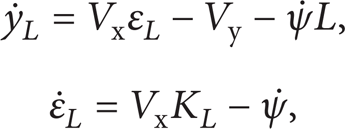
where K L denotes the curvature of the reference path, Vx denotes longitudinal velocity, Vy denotes lateral velocity, and L denotes the look-ahead distance of the vision system as shown in Figure 1.
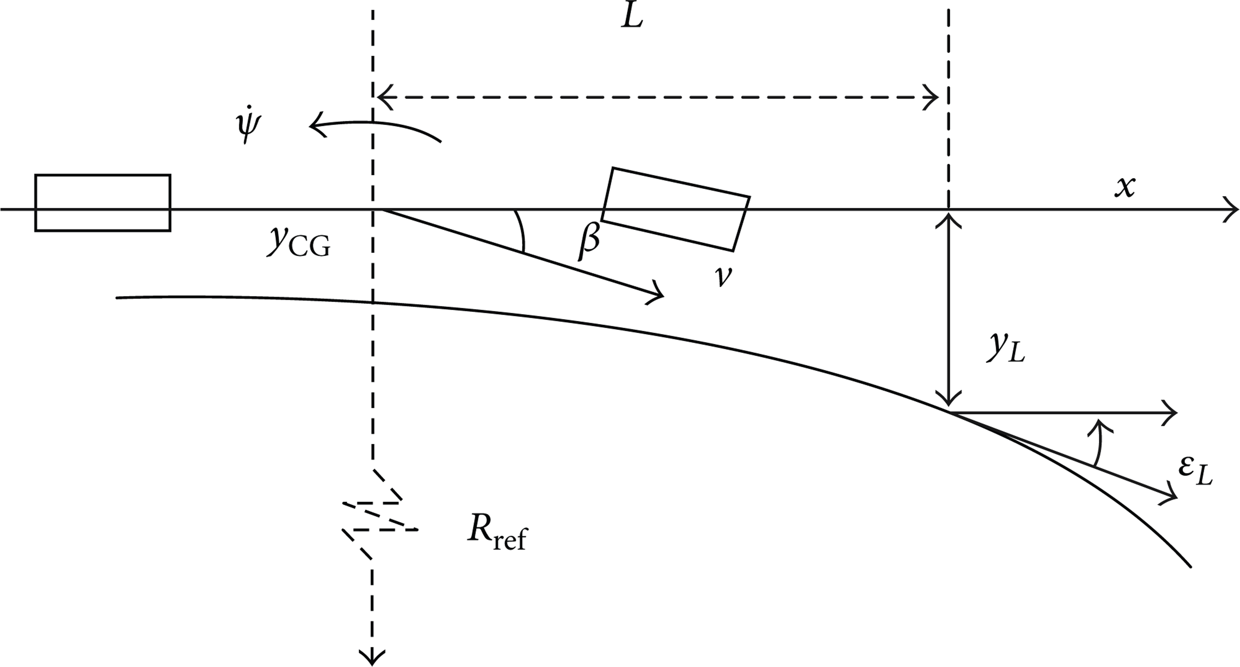
Sketch map of vehicle preview kinematics.
2.2. The Integrated Error
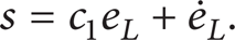
To reduce the complexity of the fuzzy controller and make the whole control system more robust and adaptive, in this paper, the sliding mode function is chosen as control object instead of the integrated error; therefore, we select the integrated error as the parameter of sliding mode function. The integrated error is the fusion of lateral error and direction error and is described as

where
3. Controller Design
The task of the lateral controller is to direct autonomous vehicles to follow the reference path in a smooth and continuous manner at the best possible precision. The dynamics of autonomous vehicles is nonlinear, time-varying, and uncertain; all of these lead to lateral control design difficultly. In order to overcome the shortage of conventional sliding mode control, a new kind of state controller is proposed by fuzzy sliding mode control theory in this paper. It does not only shorten the time of reaching the sliding mode, but it also reduces chattering for sliding mode control. Block diagram for fuzzy sliding mode controller is shown in Figure 2.
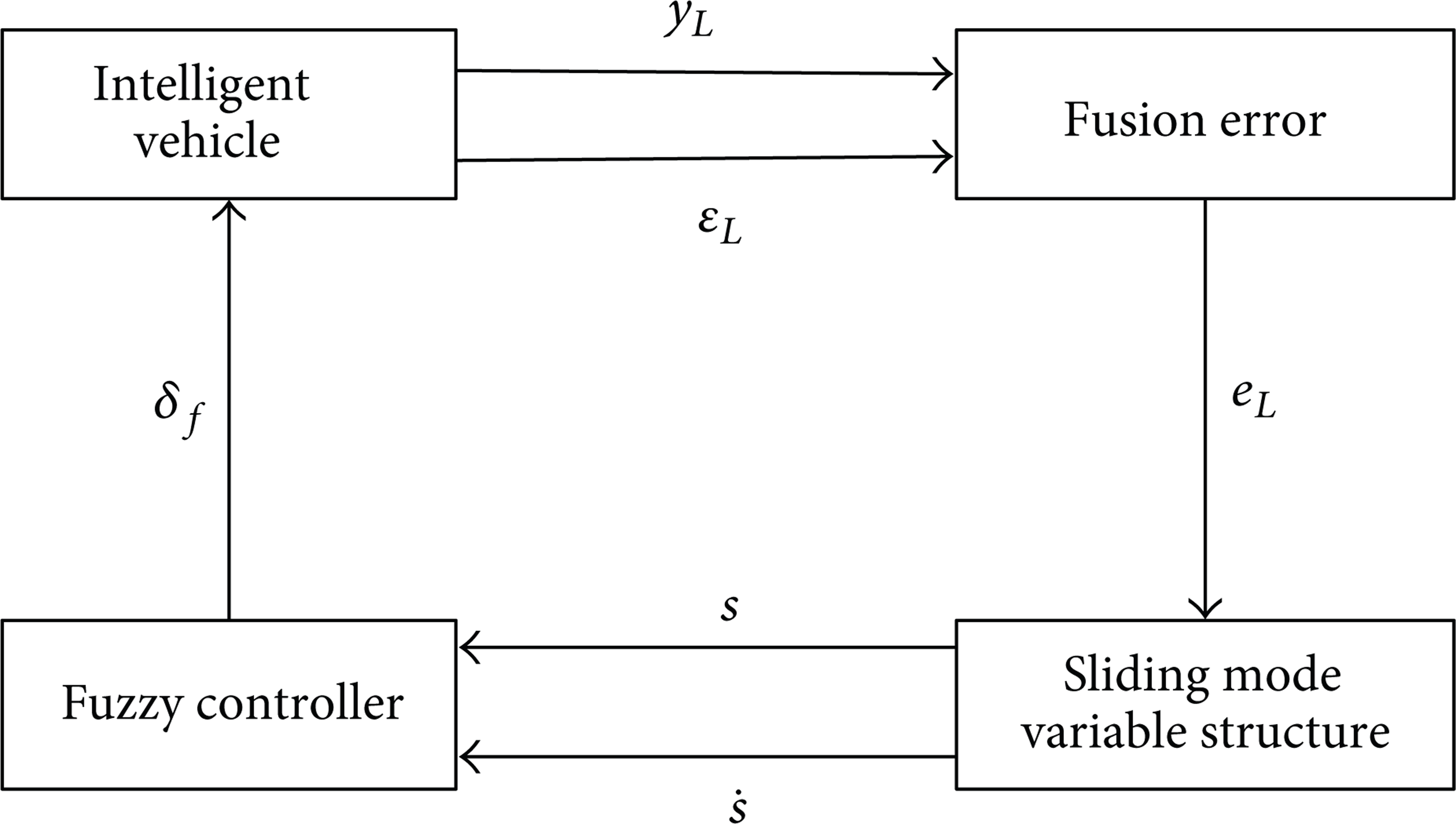
Block diagram for fuzzy sliding mode controller.

Membership functions of sliding mode surface s.
3.1. Switching Function
The conclusions of (2) are integrated error e
L
and its rate of change
In order to meet reaching condition of SMC, that is

where c1 is the sensitivity factor, e
L
is the integrated error,
3.2. Fuzzy Sliding Mode Control
Fuzzy sliding mode control (FSMC), which preserves the advantages of general fuzzy control, is the combination of the two proposed methods. At the same time, chattering produced by sliding mode control can be effectively alleviated and the robustness of the system is improved.
Sliding mode control is a control method that uses different control structures in a given hypersurface and constrains the system state vector in switching surface. It has good characteristics of robustness, self-adaptability, and implementation simplicity [10]. When the sliding mode control turns into sliding mode state, the transfer of system state will not be affected by parameter variations and external disturbance; then, the system has entire self-adaptability and robustness.
According to situations above, in order to optimize sliding mode control, the fuzzy control is adopted in this paper [11]. Here, the fuzzy controller is designed as a Mamdani fuzzy system with two input variables and one output variable. The two input variables are switching function s and switching function rate

Membership functions of sliding mode surface

Membership functions of steering angle δ f .
3.3. Fuzzy Control Rules
The fuzzy control rules play an important part in the fuzzy controller and also provide a brief description of humans' driving behavior, so it is significant to establish the fuzzy rules in the fuzzy control system. The rule-base consists of 49 rules (7 × 7) that are going to be learned with the following format:

where F
i
, Fc
i
, and T
i
are the corresponding linguistic terms. Confirm fuzzy rule in the condition of
According to the humans' driving experience and control rules' request, the fuzzy rules are shown in Table 1.
Rule base of FSMC.

In this way, it is ensured that all the possible combinations of input labels are covered by the aforementioned rule. The center-of-gravity defuzzifier is applied in this paper [10].
4. Simulation Results
In order to test the efficacy of lateral control strategy proposed in this paper, several MATLAB simulation tests are carried out. A whole vehicle dynamics model of 12 degrees of freedom is adopted; main parameters of model are taken from the experimental vehicle of DLUIV-1, which is designed by our research group. The experimental vehicle's parameters are shown in Table 2.
DLUIV-1 Vehicle parameters.

4.1. Simulation Analysis of Work State I
The reference path used in the simulation tests is initially straight with no curvature, as shown in Figure 6. Then the reference path's curvature becomes 0.05 from 0. After this, the curvature of the bending path is 0. The last part of the reference path contains two curved segments in which curvature is changing fast.
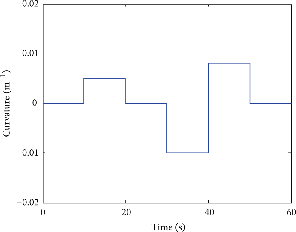
Reference path.
In the initial state of vehicle, the initial lateral error value is 0.2 m, the initial direction error value is 0.1 rad, the longitudinal velocity Vx = 5 m/s, and the preview distances L = 5 m.
Figure 7 shows the response results of steering angle for different controllers in the initial state of vehicle. The solid line denotes the system controlled by SMC, and the dotted line denotes the system controlled by FMSC and shows the change of steering angle provided by the different controllers, apparently, and it can be seen that the changes of steering angle are all within the passenger comfort range even in the serious working condition when the curve is changing very fast, but the change of steering angle controlled by FMSC is smaller than sliding mode controller by itself.
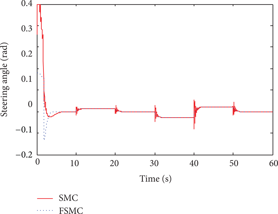
The response of steering angle.
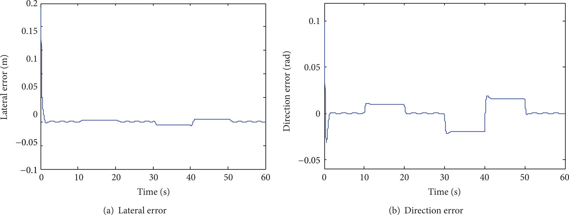
Figure 8 shows the simulation results of the lateral error and direction error in the initial state of vehicle. The steady state lateral error of FMSC is within ± 0.0015, and the steady state direction error of FMSC is within ± 0.029. From the simulation results of Figure 8, it is clear to see from that the FMSC controllers can make the lateral error and direction error approach zero in straight line segment. The results indicate that this control method is effective for tracking reference path precisely and stably.

Simulation results in the initial state of vehicle.
Due to the fact that the various physical parameters are constantly changing, relevant tests should be done to know effect on vehicle's performance of tracking reference path. In the following two cases, the autonomous vehicle starts at an initial lateral error 0.2 m and an initial direction error 0.1 rad. Firstly, Figure 9 shows the response of the lateral error and direction error for the sine change of load between −400 kg and +400 kg, respectively. The steady state lateral error is within ± 0.0023 and the steady state direction error is within ± 0.03; when load is changing according to the sinusoidal changes, it shows us that the controller has stronger robustness against disturbance. Secondly, Figure 10 shows the response of the lateral error and direction error for reference velocities of 10 km/h, respectively. The steady state lateral error is within ± 0.01 and the steady state direction error is within ± 0.02, while Vx = 10 km/h. From the simulation results, it can be seen obviously that it can speed up the convergence and efficiently suppress chattering phenomena.

Simulation results when vehicle's mass changes according to sinusoidal variation.
Vx = 10 m/s simulation results.
4.2. Simulation Analysis of Work State II
The reference path followed is different from that of the work state I, as shown in Figure 11. It is used to test the performance of FSMC in complex conditions. In this process, the reference path's curvature continues to change as time goes by.
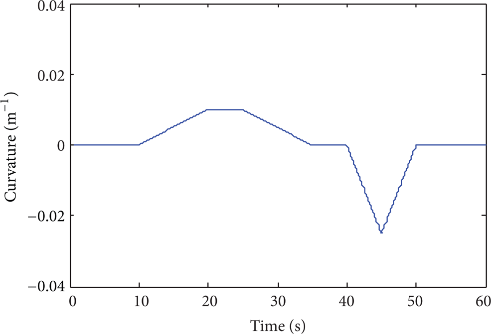
Reference path.
Figure 12 shows the response of steering angle for FMSC in the initial state of vehicle. It can be seen that the changes of steering angle are all within the passenger comfort range even in the serious working condition when the curve is changing very fast. Figure 13 shows the simulation results of the lateral error and direction error. The steady state lateral error of FMSC is within ± 0.03, and the steady state direction error of FMSC is within ± 0.07. From the simulation results of Figure 13, it is clear to see from that the FMSC controllers can make the lateral error and direction error approach zero in straight line segment. The results indicate that this control method is effective for tracking reference path precisely and stably.

The response of steering angle.

The response of lateral error and direction error.
5. Conclusion
This paper has proposed a fuzzy sliding mode controller based on visual preview distance to promote the performance of tracking reference trajectory. Different from the past is that input variables of the fuzzy controller are switching function and switching function rate, not integrated error and its rate; this change not only reduces the influence of parametric uncertainties and disturbance to the system, but also provides a good performance in tracking reference trajectory. By introducing fuzzy control, the chattering caused by sliding mode control can be effectively alleviated. The simulation results show that the proposed fuzzy sliding mode controller has stable performance with good tracking accuracy.
Footnotes
Acknowledgments
This project is supported by the National Natural Science Foundation of China (Grant no. 51107006, 61203171), China Postdoctoral Science Foundation (Grant no. 2012M510799, 2013T60278), and the Fundamental Research Funds for the Central Universities (Grant no. DUT12JS03, DUT12JR04).