
Abstract
Microforming is an emerging forming technology area in which small parts of 1 mm or less are formed under a variety of processes and process conditions. The technology is serving several industries like machine tools, medical and surgery, aerospace, atomic power, automotive, and energy sectors. Hydroforming has been a major field of interest for engineering and scientific research as well as designers and developers to look for its optimal process in terms of surface quality and part consolidation. Sheet hydroforming (SHF) process is found to be a special one for sheet metal component manufacturing formed under high fluid pressure. In this paper, an overview of various aspects of research on microforming and microhydroforming (sheet/tube hydroforming) by the authors and others in general has been presented. Most of the papers reviewed herein relate to modeling and simulation of the process and various forming issues such as process parameters, and experimental study of different alloys has been studied. Finally, current ongoing research on micro-SHF work by the authors has been introduced.
1. Introduction
Metal forming of light alloys has become very popular due to high strength to weight ratio product formation by forming processes. Automobile, sanitary, aerospace sectors, and so forth, are common due to the capability of light alloys to be formed in a variety of shapes by a variety of forming operations. Micromanufacturing, also known as microfabrication, includes processes of fabrication of miniature structures. It has the ability to manufacture products with the features of 1/1000 to about 1/20 inch in size, utilize a wide range of engineering materials, provide nano/pico-machining tolerances to microsize dimensions, and control microholding and controlling forces/pressures. Microforming is the technology of manufacturing very small metallic parts without defects, especially for mass production, as they are required in many industrial products resulting from microtechnology. These methods have very economical and ecological advantages.
While scaling down a forming process from the conventional scale to the submillimeter range, some aspects of the work piece such as its microstructure and the surface topology remain unchanged. This causes the ratio between the dimensions of the part and parameters of the microstructure or surface to change and is commonly referred to as the size effects. The size effect is very important in microforming. It is a dominant factor in design, selection, operation, and maintenance of all these elements. For example, a major problem in microforming lies in the design and manufacturing of the tools (i.e., dies, inserts, and molds). Small and complex geometries needed for the tools are difficult to achieve, especially when close tolerances and good surface quality are desired. Special tool manufacturing techniques are required to overcome these difficulties. Grain size, grain orientation, and feature size have a great influence during microforming and they cannot be neglected.
Some of the force relations concerning size effect in microforming are surface tension and gravitation. These forces are very small and can be neglected in conventional forming of macroparts. But under microforming, these forces must be taken into account, because they are relatively big as regard to the concern process forces. With decreasing specimen size and a size invariant microstructure, the share of surface grains increases, which leads to lower flow stress curves. For thin sheet metal forming, the size effect can be analyzed from two different kinds of sizes such as the feature size and the grain size.
Hydroforming is a popular forming process today to meet the challenges of various industries. Tube hydro-forming (THF) and sheet hydro-forming (SHF) are relatively complex manufacturing process. The process is better than the conventional manufacturing done via stamping and welding such as: (i) part consolidation resulting in weight reduction of the component, (ii) weight reduction through more efficient section design and tailoring of the wall thickness, (iii) reduced tooling cost, (iv) improved structural strength and stiffness, (v) less number of secondary operations, (vi) reduced dimensional variation, (vii) significant reduction in spring back effects, and (viii) reduced scrap rate. The analysis and performance of the process depend on many factors such as part geometry and design, material and process parameters, and the boundary condition of forming.
The best and easy way to study the behavior of the process for these alloys is by finite element method and computer aided engineering based procedure. The technology of product manufacturing by THF and SHF is developing very fast to shape complex profiles of sheet products. Classification of microforming process can be shown as given in Figure 1.

Classification of microforming processes.
Microhydroforming is an area to form products with less than 0.05 mm thickness, and it needs controlled blank holding and smooth container to tolerate high fluid pressure. In this paper, main investigation of microforming of different nature has been presented. Recent sheet/tube hydroforming has been reviewed, and finally, microsheet hydroforming (MSHF) work carried by the authors has been introduced.
2. Microforming
As shown in Figure 1, the process is divided into conventional and unconventional counterparts. There are several investigations on microforming carried out by different researchers across the globe. Saotome and Iwazaki [1] carried out super-plastic backward microextrusion of micropart for microelectromechanical system. The size of microgears that have been used in the research was less than 50 μm. Aluminum Al-78Zn has been used as a material in the study (Figure 2). Geiger et al. [2] carried out work analyzing systematically shaped parts to study the transition problems emerging in transferring the know-how from the macroscale to the microworld. A new solution especially for tool manufacturing and machine concepts has been investigated. Kim et al. [3] carried out finite element analysis of microrolling using grain and grain boundary elements. This study proposed a new numerical approach to simulate the microstrip rolling. The new numerical scheme has been proposed to simulate the intergranular microstrip rolling process by finite element method using grain element and grain boundary elements.
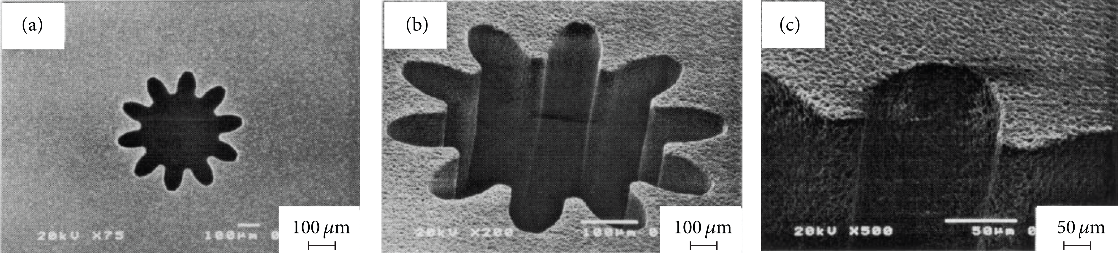
SEM microphotograph of microdie for superplastic extrusion made of photochemically machinable glass: module M = 20 μm, number of teeth Z = 10, and pitch diameterDp = 400 μm [1].
Engel and Eckstein [4] carried out recent review of the literature on development of microforming applications and ways to finding solution for solving the problems related to microforming have been suggested. Liu et al. [5] carried out application of microforging to SiCN MEMS fabrication implementing numerous SiCN ceramic (MEMS) microstructures (Figure 3). Egerer and Engel [6] carried out process characterization and material flow study in microforming at elevated temperatures. It has been observed that inhomogeneous material characterization can be performed at elevated temperatures too. Results gained by upsetting and backward extrusion could show that temperature influences the forming result, tending to homogenize the material flow. Cao et al. [7] carried out experimental investigation of the extrusion process for producing micropins along with their numerical simulation using RKEM. A forming assembly setup was fabricated in conjunction with a loading substage to extrude micro pins having a final diameter of 1 mm. The effect of grain size has also been investigated by modifying the workpieces by heat treatment so as to produce grain sizes varying from 32 μm up to 211 μm. Two extrusion dies of different roughness were also used to study the effect of surface finish using FE-based simulation and experiments.

Microforged model [5].
Geißdörfer et al. [8] carried out FE simulation of microforming processes using a mesoscopic model to study and identify the size effects on forming. A large number of experiments were carried out comparing the numerical results with simulation.
Wang et al. [9] carried out coining tests during coining process to study the size effects of possible cavity dimensions of microbillets of pure aluminum having groove width from 40 to 120 μm at temperature of 400°C. The experimental results show that the microforming ability decreases with increasing ratio of L/b ratio. When this ratio L/b is less than 0.5, microforming ability is good. When the ratio L/b is larger than 0.5, the ability is not very good. It is also reported that the phenomena might be analyzed from the viewpoint of multigrain structure of billet as well. Hirota [10] fabricated a setup using a microbillet to study microsheet extrusion process. Experiments were carried out having extrusion ratio of 2 using a pure aluminum sheet of 2 mm thickness and having a billet of 1 mm in diameter. The FE results were explained by comparing the flow patterns estimated by simulation. It was observed that the billet heights estimated in the analysis agreed well with the experiments. Peng et al. [11] carried out study on size effects in thin sheet metal forming process under elastic-plastic constitutive models. It is observed that in micro-forming, the material deformation behavior is affected by grain size, grain orientation, and the feature size. Since, the most commonly used parameters to describe the material behavior are flow stress and the flow curve. It is found that, with increasing miniaturization, the flow stress is influenced by size effects, and that can be explained by the surface model.
Li et al. [12] carried out microstructural study of Zn-Al4 alloy on microcastings of parts using microprecision casting having a micro-metal mold created using precision casting method. Three-dimensional complicated microgear castings were produced, and evolvement regularity of microgear castings was observed by optical microscope and scanning electron microscope. The comparison of microcasting result with conventional casting result has been characterized by typical nonequilibrium solidification method (Figure 4).

Image of microgear [12].
Manabe et al. [13] validated experimentally the FE simulation result based on surface roughness model in micro-deep drawing. To verify the validity of the FE model of surface roughness in the micro-deep drawing process, a new high-precision sequential blanking and drawing setup was developed for the experiment and a microcup with 500 μm diameter was fabricated from stainless steel (SUS304) ultrathin foil of 20 μm thicknesses.
Yang et al. [14] carried out microprecision casting based on investment casting for microstructures of high aspect ratio using centrifugal method. The microparts of Zn-4%Al alloy with an aspect ratio up to 200 were produced at the centrifugal speed of 1500 RPM with mold temperature of 270°C. The investigations on the relationship between flow length and rotational speed were also carried out. Ocaña et al. [15] carried out laser shock microforming of thin metal sheets with ns Lasers. The physics of laser shock microforming and the influence of the different experimental parameters on the net sheet bending angle were presented.
Fu et al. [16] studied experimental and simulation study of microblanking and deep drawing compound process using copper sheet to investigate the size effect. A similarity theory has been employed in die design and deformation process simulation. The grain size effect was studied by preparing the copper sheets of different grain sizes, while the feature size effect was studied via using different punch radii. Based on the analysis of experiments, it has been found that the deformation load decreases with the increase of grain size, which is not very significant as only a few grains in the cross-section of the sheet metal (Figure 5) appeared.
Images of micro-deep drawing [16].
3. Principles in Hydroforming
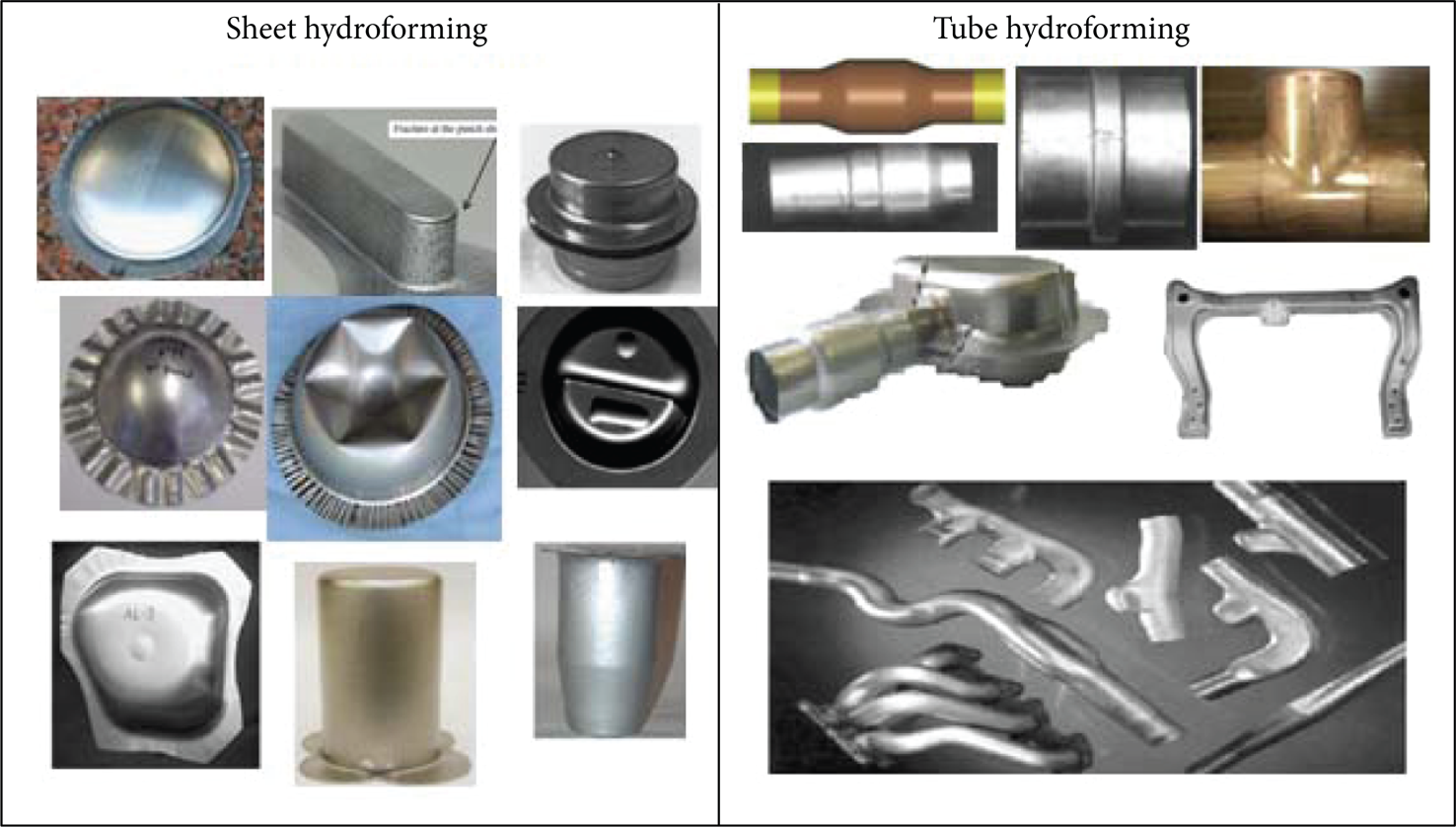
Hydroforming can be divided into sheet hydroforming (SHF) and tube hydroforming (THF). Figure 6 shows classification of various hydroforming processes, and Figure 26 shows the applications and some of their common products. The working principle for sheet hydroforming is shown in Figure 7. After blank setting and blank holding, the punch pushes the sheet metal into the die cavity, while oil or liquids high pressure is applied on other side by a press to flow the sheet metal tightly onto the punch to generate a shape. The effect of friction retention is affected. At the same time the liquid in the die cavity will flow out between the upper surface of the die and the sheet metal. Therefore, fluid lubrication reduces the frictional force.
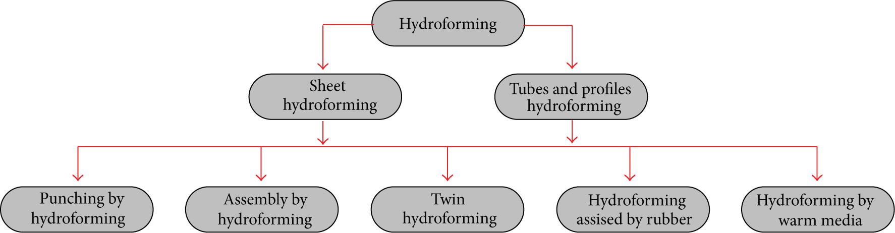
Classification of hydroforming process [25].

Sheet hydroforming: (a) blank setting, (b) blank holding, (c) drawing, and (d) finishing [25].
Tube hydroforming is a process of forming closed and hollow section of different cross-sections by applying an internal hydraulic pressure in conjunction with end axial feeds. A tube is placed in the tool cavity, whereby the geometry of the die corresponds to the external geometry of the produced part (Figure 8). These tools, in most cases separated in longitudinal direction, are closed by the ram movement of a press, and the tube ends are loaded by two punches moving along the tube axis. Each of the loads applied to the tube ends for sealing the tube's interior must be at least equal to the force calculated from the product of the tube's internal area and the tube's internal pressure. However, the axial forces may be increased to a higher value if the forming job requires them, and then the additional tube wall material is brought into the tool cavity. Internal pressure is increased during the process until the expanding tube wall comes into contact with the inner surface of the die cavity. This principle may be used for hydroforming both straight and prebent tubes. Figures 9, 10, 11 and 12 show schematic diagram of different types of sheet hydroforming process.

Tube hydroforming: 1: tube, 2: lower die, 3: upper die, and 4: axial punch [25].

Hydromechanical deep drawing [25].

Hydroforming using a membrane diaphragm [24].

Hydraulic stretch forming [24].

Double blank hydroforming [24].
3.1. Sheet Hydroforming
There are some investigations about sheet hydroforming by Zhang [17] investigating a brief review of recent developments in the area of hydroforming and their relevant history with process variations for forming tubular and flat components. Applications of shell type products have also been reported in most of German aircraft. Hein and Vollertsen [18] carried out an investigation about hydroforming of sheet metal pairs and numerical and experimental study wherein hydroforming of sheet metal pairs (a new class of HF) has also been investigated concerning different models, simulations, and experiments on unwelded sheet metal pairs. It is found that numerical simulations and experimental study influence various parameters on the process feasibility and the result of experiments confirmed the FEM simulations results.
Novotny and Hein [19] carried out an investigation about SHF of Al alloys (AA6016-T4) and illustrated the advantages of SHF over other alloys. It is found that SHF of aluminum alloy has good mechanical properties. Zhang et al. [20] proposed a movable die for SHF process and carried out numerical and experimental study to improve the forming characteristics of alloys. The limit drawing ratio of the sheet was improved. This process is especially suitable for forming of small batch production of sheet metal parts with complicated shapes (Figure 13).

A new setup for sheet hydroforming with a movable female die [20].
Zampaloni et al. [21] carried out numerical and experimental investigations in stamp hydroforming by using pressurized viscous fluid (for aluminum (3003-H14-Aluminum) alloy), wherein one or both surfaces of the sheet metal are supported with a pressurized viscous fluid to assist with stamping of the part (thus no need for female die). The pressurized fluid has several purposes: (a) supports the sheet metal from the start to the end of the forming process, thus better deformation, (b) delays the onset of material failure, and (c) reduces wrinkle formation. Experiments show draw depths improvements up to 31% before the material failed.
Zhang et al. [22] have carried out a new SHF technology using a movable die comparing between THF and SHF and used a movable female die in SHF. Where in SHF technology are summarized with respect to increase in the feeding of materials and local deformation capacity for SHF. Development of SHF technology is still much slower than that of THF technology. Lang et al. [23] investigated recent development of SHF for lightweight components and expressed the requirements of press control equipment. Ahmetoglu et al. [24] carried out numerical and experimental research about application of viscous pressure forming (VPF) for nonsymmetric steel, aluminum, and nickel parts. FEM simulation and blank holding force control were used for optimizing the process conditions. It has been discussed effect of process variables upon the achievable part geometry. Comparison between FEM results and experiments illustrated simulation was used to predict material flow with high accuracy.
Merklein et al. [25] carried out numerical and experimental study for joining tube and double sheets in hydroforming. Both of the tube and sheets were formed simultaneously jointed. The finite element analysis and laboratory trials were used to design the die cavity so as to avoid the wrinkling of material tearing and the collapsibility of the tube section during forming. The analytical model of the author predicts the experimental conditions well. Abedrabbo et al. [26] carried out an important investigation about wrinkling behavior of aluminum alloys during SHF. In this research FEM and experimental study have been implemented for 6111-T4 aluminum alloy. It shows that the use of pressurized fluid delays the onset of material rupture and acts as a blank holding force to control wrinkling in the flange area. An optimum fluid pressure profile generated by FEM was applied in SHF to make the deep drawn hemispherical cup without tearing and with minimal wrinkling in the flange area. The FEM model predicts the location of the material rupture in pure stretch and wrinkling characteristics of the aluminum alloy sheet (Figures 14 and 15).

Numerical and experimental result of draw-in without fluid pressure for the 101.6 mm punch with 4 mm gap between the upper and lower dies. Draw depth = 50.8 mm [26].
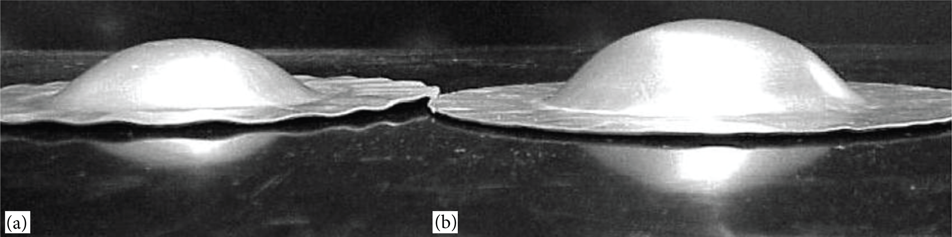
Draw-in experiments: (a) without fluid pressure and a punch depth of 17.8 mm, (b) with fluid pressure and a punch depth of 30.5 mm [26].
Lang et al. [27] carried out numerical and experimental study of hydromechanical deep drawing (HDD) by using very thin middle layer in multisheet hydroforming. The main advantage of SHF has been to be of uniform pressure transferred to everywhere. Some features on the formed forced internal, external, and middle layers including high drawing ratio, wall thickness distributions, free wrinkling, and fracture were also discussed (Figure 16). Hama et al. [28] carried out numerical and experimental study on elliptical deep drawing using an elastoplastic FEM (code STAMP3D) program. Where in simulated result could predict experimental result about the thickness strain distribution. The comparison between conventional process and SHF process (numerically and experimentally) shows that SHF gives better formability.

Triple-layer sheet hydroforming based on HDD with uniform pressure onto the blank. (1) punch, (2) blank holder, (3) container, (4) die cavity, (6) prebulging pump, (7) relief valve, (8) proportional pressure relief valve, (9) single-direction valve, and (10) oil tank [27].
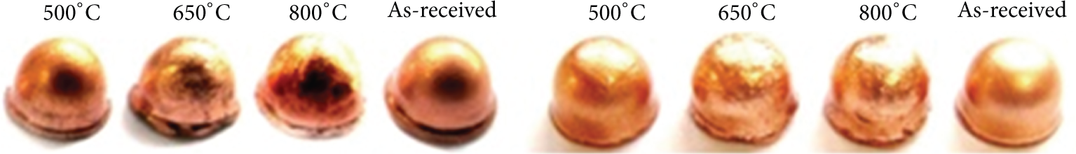
Murr et al. [29] carried out investigation about metallurgical and microstructural characterization of a hydroformed steel part. Microstructural characterization by light optical metallography (LOM) and transmission electron microscopy (TEM) (including grain structures) was carried out (Figure 17). Hojjati et al. [30] simulated superplastic forming in hydroforming process. The investigation of aluminum alloy 5083 in hydroforming process was simulated at three different constant pressures, and the effect of pressure on thickness distribution and final dome height were evaluated. The paper shows that titanium alloys (Ti-6Al-4V, Ti-6Al-2Sn-4Zn-2Mo) and aluminum alloys (5083, 7475) are typical examples of metallic superplastic materials. It is observed that low flow stress and high sensitivity of flow stress to strain rate are the main feature of superplastic deformation.

Images of microstructure: light optical microscopy (LOM) and transmission electron microscopy (TEM) of a hydroformed product of 304 stainless steel before annealing (a) and after annealing (b) [29].
Singh and Ravi Kumar [31] carried out studies to see the effect of process parameters on product surface finish and thickness variation in hydromechanical deep drawing. Sharma and Rout [32] carried out finite element analysis and experimental study on sheet hydromechanical forming of circular cup by using LS-DYNA.
Forouhandeh et al. [33] fabricated an SHF setup for cup forming of aluminum, copper, and brass sheets. The advantage of sheet hydroforming process over conventional deep drawing has been studied and illustrated using rigorous microstructure analysis (Figure 18). Table 1 shows the recent literature review on sheet hydroforming by many authors.
Literature review on SHF.


Microstructure of hydroformed cup shape product of copper before deformation/flange area (a), middle deformation/wall area (b), and maximum deformation/maximum depth of dome (c) under magnification 50x (by authors) [33].
3.2. Tube Hydroforming
The work reported by Woo [34] incorporates experimental and analytical result for tubes bulged under internal pressure and axial compressive loading under a numerical study assuming the entire length of the bulged tube to be in tension, and thus, free bulging took place. The comparison of experimental and theoretical results indicated good agreement when stress-strain properties of tubes obtained from biaxial tests were used in calculations.
Limb et al. [35] used oil as the pressurizing medium in their experiments to investigate forming of copper, aluminum, low carbon steel, and brass tee-shaped tubular parts. Results with different lubricants and material evaluations were reported in terms of protrusion height attainable. Sauer et al. [36] presented the theoretical and experimental work on necking criterion of bulged tubes.
Woo [37] and Woo and Lua [38] described their experimental tooling and presented their theoretical analysis based on the stresses and strains taking into account the anisotropy effect of the sheet metals in separate papers. Manabe and Nishimura [39] investigated the influence of strain-hardening exponent and anisotropy on the forming of tubes in hydraulic bulging and nosing processes. They briefly presented the maximum internal pressure as a function of tube radius, thickness, strain hardening exponent, and strength coefficient assuming no axial loading. Manabe et al. [40] worked on deformation behavior and examined the limits of forming for aluminium tubes under both internal pressure and axial force. Axial cylinders and internal pressure were controlled by a computer control system to obtain predefined stress ratio during their experiments. Fuchizawa [41] analyzed the bulge forming of finite-length, thin-walled cylinders under internal pressure using incremental plasticity theory.
Asnafi [42] used analytical models to see the limits of free forming and the influence of different material and process parameters on loading path and the corresponding forming limit result. It was also pointed on the type of experimental investigation to be carried out for hydroforming. Lei et al. [43] developed a FEM program “HydroFORM-3D” for analyzing and designing the tube hydroformed parts for automobile rear axle housing and subframe. Ray and Mac Donald [44] conducted experimental studies for X- and T-branch components for different loading paths (forming pressure and axial feed) via data acquisition system integrated with THF machine and compared the results with simulation values. There have been efforts to help industry people by developing a computer aided process planning system (CAPPS [45]) for THF products (Figure 19). Table 2 shows most of literature review on tube hydroforming and the related contributions by different authors.
Literature review on THF.


Effective strain distribution during X-branch tube hydroforming (THF) (a) and effective stress distribution during T-branch THF (b) (finite element simulation) [45].
Nowadays, commercially pure titanium (CP Ti) is being paid much attention due to its properties of lightness, high specific ratio of strength to weight, strength against high temperature, antirust, and good adaptability for a living body. Sheet hydroforming of CP Ti sheets is especially important for the production of thin-walled structural components used in the electronics and aerospace products such as the cover cases of the notebook camera, and mobile phone. But low ductility, high spring back, and sensitivity against atmosphere elements especially oxygen above recrystallization temperature of titanium make some limitations in forming. Forouhandeh et al. [46] carried out simulation modeling and parametric study of sheet hydroforming process for commercially pure titanium grade 1 for cup shape products using DEFORM-3D package and optimized the process in terms of defect-free products.
3.3. Microhydroforming
Microhydroforming is an area to form products with less than 0.05 mm sheet under controlled hydraulic pressure. There are few investigations about the microhydroforming as given below.
Zhuang et al. [47] carried out experimental and numerical investigation of localized thinning in hydroforming of micro-tubes. To investigate the localized thinning mechanism, an integrated crystal plasticity finite element (CPFE) modeling system has been developed. A simplified plane strain CPFE model has been presented and used to investigate the localized thinning and failure features in hydroforming of microtubes. Thickness of tube has been selected around 30.4 μm (Figure 20).
Close-up view of the failure in microtube hydroforming [47].
Hung and Lin [48] fabricated microflow channels (0.051 mm thickness) for metallic bipolar plates (SUS304) by high-pressure hydroforming apparatus to enable a two-stage pressure increase in the hydroforming process having three-layered tapered cylinders to sustain 1230.17 MPa working pressures (Figure 21).
Hydroformed samples [48].
Currently, Forouhandeh et al. carried out finite element simulation and experimental study on microsheet hydroforming of microcup with 0.05 mm thickness and of CuBe2% alloy. In the work, a microsheet hydroforming setup has been designed and fabricated for producing microcups (Figures 22, 23, and 24). The microcups have been formed under two conditions, first with die cavity and fluid pressure from upper side and secondly with punch and fluid pressure from bottom side (oil container). The parts formed have been found without wrinkling or tearing and with minimum required forming force by the hydromechanical cup drawing. Maximum forming load by the simulation is found to be 1.66 KN and by experimental study is found around 1.50 KN. Therefore, result of FEM simulation had good agreement with experiments. The work would be reported in detail in the future. A generative computer aided process planning (CAPP) system has also been developed for sheet hydroforming of CP titanium grade 1 having symmetric and nonsymmetric shapes (Figure 25) [49].
Details of geometry of microsize product (original drawing).
Stress distribution of microcup (optimized in hydromechanical cup drawing, finite element model (authors' work)).

Microhydroformed cup (experimental study) (a) and microhydroforming setup (b, c, and d) (authors' work).

Process planning for sheet hydroforming of CP titanium for symmetric shape (authors' work) [49].
4. Modeling Techniques
There are several modeling techniques reported in the literature [50, 51] like upper bound and finite element techniques. The upper bound has been used mostly for modeling microcup forming [2, 9, 52] including size effects parameter. Finite element method has been formed very suitable as far as the Lagrangian updated modeling is concerned [11]. The beauty of FEM-based modeling has been well accepted by researcher for process parameter design and tooling design for microsheet hydroforming [26, 28, 30, 33, 46]. However, these techniques are further required to be included: the effect of size, tolerances, and micro structure for microforming processes.
5. Conclusion
In this work, a recent literature review on topics such as microforming, sheet hydroforming, tube hydroforming, and microhydroforming has been carried out. Most of the works include a review of recent developments taking place in the area of SHF and THF. Numerical (FEM-based analysis) and experimental study on SHF and THF processes indicates some new methods using female die in SHF having optimized conditions to avoid tearing and wrinkling of work material, and thus, avoiding the bursting and thinning during the THF. Different newer investigations about microforming and microhydroforming are also reported. There are certain experimental challenges such as optimization of the process parameters (blank holding force, lubrication, backward pressure, punch speed, etc.) related to SHF of CP titanium and titanium alloys. microstructure analysis of hydroformed titanium parts is a new area and still to be explored for SHF application. Different investigations on microforming and especially microsheet hydroforming (numerical and experimental) for producing microcups of CuBe2% alloy (with 0.01 to 0.05 mm thickness) have been newly introduced by the authors. Fabricated microsheet hydroforming setup by the authors has been used for the above tests. Finally, it can be said that micro-SHF would be very useful for small complex products. The authors believe that, in this review paper, more details of design and experimental study of micro sheet hydroforming and result comparison between finite element simulation and experimental study have not been elaborated and will be reported in detail in subsequent publications.