
Abstract
Torsional spring-loaded antibacklash gear which can improve the transmission precision is widely used in many precision transmission fields. It is very important to investigate the dynamic characteristics of antibacklash gear. In the paper, applied force analysis is completed in detail. Then, defining the starting point of double-gear meshing as initial position, according to the meshing characteristic of antibacklash gear, single- or double-tooth meshing states of two gear pairs and the transformation relationship at any moment are determined. Based on this, a nonlinear model of antibacklash gear with time-varying friction and meshing stiffness is proposed. The influences of friction and variations of torsional spring stiffness, damping ratio and preload on dynamic transmission error (DTE) are analyzed by numerical calculation and simulation, and the results show that antibacklash gear can increase the composite meshing stiffness; when the torsional spring stiffness is large enough, the oscillating components of the DTE (ODTE) and the RMS of the DTE (RDTE) trend to be a constant value; the variations of ODTE and RDTE are not significant, unless preload exceeds a certain value.
1. Introduction
With the advantages of high transmission efficiency, running stability, and high driving accuracy in one-way drive mode, gear transmission is a principle kind of drive, widely used in various mechanical systems and equipment. However, the gear backlash caused by side clearance leads to response lag in some servomechanism [1] which reduces the control accuracy seriously. Therefore, in order to improve the driving accuracy, some suitable methods of error control must be used in some fields which need to transfer high accuracy angle or position information, such as double electric motor method, double helical gear antibacklash method, adjusting center distance method, and spring- (or torsional spring-) loaded antibacklash method [2–8]. Among others, the spring-loaded antibacklash gear invented in 1952 or earlier [8] is extensively used in numerous fields of industrial robot [3], precision servos [5, 6], radar antennas [7], and precision machine tools.
In order to eliminate backlash, most methods above are with the method of increasing preload by artificial means. However, increased friction caused by preload is the major factor of wear, noise, and vibration. Many precision mechanisms with antibacklash gear require the dynamic characteristics of high speed, high accuracy, and high stability [6], and the antibacklash gear also is under the complex work conditions of often starting, commutation, and braking. Thus, the internal excitations of antibacklash gear such as time-varying meshing stiffness, friction, and damping have effects on dynamic performance of whole system, which is worth studying.
There were lots of research achievements on gear dynamics modeling and analysis, which were reviewed in Özgüven and Houser's paper [9] and Wang et al.'s paper [10]. Özgüven and Houser [9] reviewed the mathematical models and dynamic characteristics before 1986, and most of them were linear. Nonlinear dynamics of spur gear pair using harmonic balance method were studied by Kahraman and Singh [11–13]. In paper [13], the backlash and time-varying meshing stiffness were considered; Theodossiades and Natsiavas [14] investigated dynamics of a gear-pair system with backlash and time-varying mesh stiffness, and the system was under the action of external excitation, caused by torsional moments and gear geometry errors; Vaishya and Singh [15] proposed alternative strategies for incorporating the phenomenon of sliding between gear teeth, and time-varying meshing stiffness was considered in their paper. From the recently published papers [16–18], more realistic and exact gear model with multiparameters excitations and strong nonlinearity will be one of the research trends.
At present, however, most of studies about antibacklash gear focus on structure design and calculations, transmission accuracy and applications. Boyuan and Zhiwu [7] analyzed the static force of the antibacklash gear in a transmission mechanism and estimated the composite transmission error. An antibacklash gear was used in a kind of farm tractor to reduce the noise of power takeoff system by Shim et al. [4], and the vibration and noise were analyzed by a simulation model which was validated by experiment.
There are fewer studies on the nonlinear dynamic including frequency characteristic, contact stiffness, and dynamic transmission error, of antibacklash gear. A simplified torsional dynamic model was established, and the natural frequency was analyzed and estimated by Guoming [2]. Imasaki and Tomizuka [3] proposed an approximate stiffness model of an antibacklash with the characteristic of three-segment flexible joint which was used in a manipulator. A dynamic model with friction of antibacklash gear servomechanism by Kwon et al. [5] and the stiffness model of antibacklash gear were similar as three-segment flexible joint characteristic. Allan and Levy [6] proposed a method for estimating the minimum preload torque required to obtain a satisfactory step response from a position control system with spring-loaded antibacklash gear.
The above studies on the antibacklash gear did not mention the time-vary meshing stiffness and friction with the characteristics of multimeshing points. In this paper, an antibacklash gear transmission mechanism is studied. Applied force between each two gears is analyzed completely. Meshing timing of every meshing point is defined and the phase difference between positive rotation and reversal is calculated. Based on this, a nonlinear dynamic model considering friction, side gear clearance, and nonlinear time-vary meshing stiffness is proposed, and the influences of friction and variations of torsional spring stiffness, damping ratio, and preload on dynamic transmission error (DTE) are analyzed by numerical calculation and simulation.
2. Description and Assumptions of Antibacklash Gear
As shown in Figure 1, gear g1 is the pinion; gear g2 is called as fixed gear; gear g3 is a free gear called loaded gear. G2 and g3 connected by a torsional spring rotate relatively an angle of some teeth, and torsional spring is preloaded at this point, then g2 and g3 as a gear together engage with g1. Two sides of a tooth of gear g1 contact, respectively, with a tooth of g2 and a tooth of g3 under the action of torsional spring force. Therefore, there is no backlash in transmission no matter it is in positive rotation or in reversal.
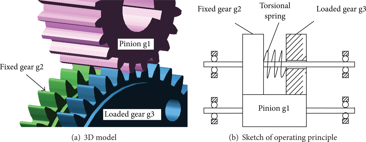
Structure of antibacklash gear.
There are some assumptions before modeling and analysis: (1) ignoring the effects of stiffness and damping of each shaft; that is, the model is considered as a torsion vibration model; (2) ignoring the effects of stiffness of lubricant film to contact stiffness; (3) contact conditions meet Hertz contact theory.
3. Applied Force Analysis of Each Two Gears
3.1. Applied Force between Pinion g1 and Fixed Gear g2
The relative displacements in line of action of gear pair g1g2 and g1g3 are defined as x1 and x2, also called dynamic transmission error (DTE), and x1 = rb1θ1 – rb2θ2, x2 = rb1θ1 – rb2θ3, where rb1 is the radius of base circle of g1; rb2 is the radius of base circle of g2 and g3; θ1, θ2, and θ3 separately are rotation angle of g1, g2, and g3. In order to describe conveniently, the equivalent relative displacement xtor of rotation angle difference between g2 and g3 to line of action is written as xtor = rb2 (θ2 – θ3), called DTE, too. The direction of anticlockwise is defined as positive rotation while clockwise as reversal. As shown in Figure 4, the initial state is the time when gear pair g1g2 is entering into the double-tooth meshing area (DMA) in positive rotation.
When antibacklash gear running, gear g1 is stressed by both g2 and g3. Gear g2 and g3 are connected by a torsional spring. The force analysis of each gear is done as follows, based on the assumption of all gear pair in the single-tooth meshing area (SMA).
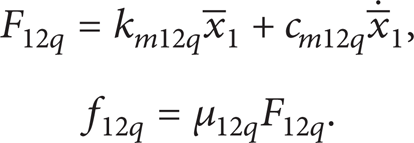
As shown in Figure 2, there are 3 position relations in gear pair of g1 and g2: normal contact (Figure 2 (a)), isolation (Figure 2 (b)), and abnormal contact (Figure 2 (c)). In point p (p maybe A1 or B1 in double-tooth meshing area), the contact force and friction between g1 and g2 are written as
where km12p, cm12p, and μ12p are, respectively, the time-varying meshing stiffness, damping coefficient, and instantaneous friction coefficient of gear pair g1g2 in point p, and the calculation formulas of time-varying meshing stiffness km12p and instantaneous friction coefficient μ12p are given in Appendices A and B;

Meshing states of g1 and g2.
For the definition of composite transmission error
(1) When gear pair g1g2 is in the state of normal contact and in positive rotation, if
(2) When gear pair g1g2 is in the state of isolation and in positive rotation, if

where α w is the pressure angle of pitch circle; E rmi is the mean value of feed errors of gear i; E ri is the feed tolerance of gear i; F ii ″ is the radial composite error of gear i; f a is the centre distance deviation.
A flag variable flag is defined to switch positive rotation and reverse of g1 as
Thus, the composite transmission error of g1g2 can be expressed by
(3) When gear pair g1g2 is in the state of abnormal contact, if
3.2. Applied Force between Pinion g1 and Loaded Gear g3
Likewise, gear pair g1g3 also is in one of 3 states: normal contact (Figure 3 (a)), isolation (Figure 3 (b)), and abnormal contact (Figure 3 (c)).

Meshing states of g1 and g3.

Meshing points and position definition of antibacklash gear.
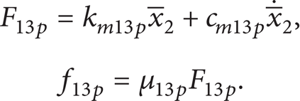
Similarly, the contact force and friction between g1 and g3 in point q (q maybe A2 or B2 in double-tooth meshing area) are expressed as

where km13q, cm13q, and μ13q are, respectively, the time-varying meshing stiffness, damping coefficient, and instantaneous friction coefficient of gear pair g1g3 in point q;
In like manner,
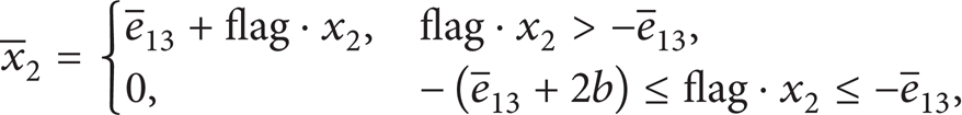
where
When gear pair g1g3 is in the state of abnormal contact, if
Generally, in order to ensure antibacklash gear work steadily, these states shown in Figures 2 (b), 2 (c), 3 (b), and 3 (c) must be avoid. Calculation results show that these states would arise, unless preload or stiffness of torsional spring satisfies (9a) and (9b):

or

where J2 is the moment of inertia of g2 and g3; amax is the maximum value of relative acceleration of g2 and g3; T2 is the load torque.
Among others, the states in Figures 2 (c) and 3 (c) are not considered in the rest calculations bellow.
3.3. Applied Force between Fixed Gear g2 and Loaded Gear g3
Tpre is the preload torque of antibacklash torsional spring; then Tpre = rb2Fpre. When the angle difference of gear g2 and g3 changes, the interaction torque T23 of g2 and g3 changes as well. It is easy to know that T23 = ktor (δθ + θ3 – θ2) in positive rotation, where ktor is the torsion stiffness of torsional spring; δθ is the initial torsion angle in preload torque of torsional spring, ignoring the effects of gear tooth deformation, and δθ = Tpre/ktor; θ2, θ3 are, respectively, the angles of gear g2 and g3.
When gear g1 is in reverse, T23 = ktor (δθ + θ2 – θ3). Thus, T23 = ktor (δθ – flag · (θ2 – θ3)).
The equivalent applied force F23 of torque T23 to the line of contact, considering damping, is expressed as

where k x is the equivalent linear stiffness to the line of contact and k x = ktor/rb22; F23 = T23/rb2; δxθ = δθrb2; c23 is the equivalent damping coefficient of torsional spring.
4. Nonlinear Dynamic Model
4.1. Determination of SMA or DMA of Gear Pair G1G2
Without consideration of oil film rigidity, the composite meshing stiffness of normal gear pair is dependent on 2 factors: (1) quantities of meshing points; (2) time-vary meshing stiffness of single meshing point. The quantity of meshing points is dependent on contact ratio of each gear pair. In the paper, the contact ratio of each gear pair is 1 ≤ ∊ < 2; thus the maximum quantity of meshing points is 4. The quantity is periodic variable within certain configure of structure and assembly parameters.
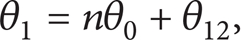
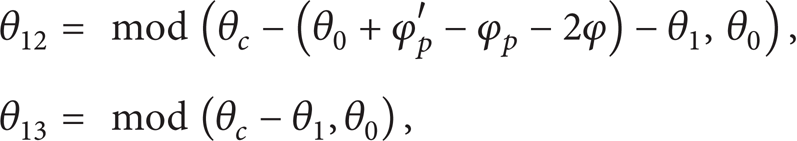
When gear g1 is in positive rotation, in Figure 4, meshing point Bs12 is defined as the initial double-tooth meshing point (IDMP) of gear pair g1g2 in line of contact N1N2, and let tBs12 = 0, while Bs13 is the IDMP of gear pair g1g3 in line of contact N1′N2′. The nearer meshing point to the IDMP is defined as A i , and the farer point as B i (i = 1 or 2). θ12 is the rotation angle of gear g1 from Bs12 to A1 along the line of contact, and θ13 is the rotation angle of gear g1 from Bs13 to A2. Thus, the rotation angle of gear g1 θ1 is
where n is the number of mesh cycles, nonnegative integers; θ0 is called meshing cycle angle which is the rotation angle of gear passing through a double-tooth meshing area and a single-tooth meshing area along the line of contact. According to the involute principle, ignoring the effect of base pitch error, the meshing cycle angle is calculated by

where P b = πmcosα w ; ΔF pb is the base pitch error; m is the gear module; α w is the working pressure angle, in X-zero gear pair and gear pair with reference canter distance, α w = α.
According to (11), θ12 = MOD (θ1, θ0), where MOD (a, b) is the function in MATLAB for getting modulus after division.
As shown in Figure 4, let
When d12 ≥ S – P
b
; that is, θ12 ≥ (S – P
b
)/rb1 = θ
c
, gear pair g1g2 enters single-tooth meshing area, where S is the length of actual line of action,
Thus, when θ c ≥ θ12 ≥ 0, gear pair g1g2 is in the double-tooth meshing area. When θ0 ≥ θ12 ≥ θ c , gear pair g1g2 is in the single-tooth meshing area.
4.2. Determination of SMA or DMA of Gear Pair g1g3
In Figure 5 (a), gear g2 and g3 are in the symmetrical position about Y-axis. According to the theory of engagement, when g1 rotates an angle φ in counter-clockwise direction as shown in Figure 5 (b), gear pair g1g3 meshes at pitch point P; symmetrically, when g1 rotates an angle φ in clockwise direction, gear pair g1g2 meshes at P, too. Angle φ is calculated by

where s2 is the tooth thickness of gear g2 or g3, s2 = m(π/2 + 2xtanα) + As2, where x is the distance coefficient between the middle line of outline of cutting tool and pitch line of cutting tool; As2 is the deviation of tooth thickness [19].

Determination of phase difference of gear pair g1g2 and g1g3.
Thus, when gear pair g1g2 meshes at IDMP Bs12; that is, t = 0, the counter-clockwise angle of gear g1 along the line of contact N1′N2′ of gear pair g1g3 is θ13|t = 0, θ13|t = 0 = φ p ′ – φ p – 2φ, where φ p ′ is the angle of g1 from Bs13 to P, along N1′N2′ in counter-clockwise direction; φ p is the angle of g1 from Bs12 to P, along the line of contact N1N2 of gear pair g1g2 in counter-clockwise direction:

where
So, θ1 = nθ0 + θ13 – φ
p
′ + φ
p
+ 2φ, θ13 = MOD (θ1 + θ0 + φ
p
′ – φ
p
– 2φ, θ0). Let
4.3. Relationship and Phase Analysis of Positive Rotation and Reversal
When gear g1 is in reversal and θ1 > 0, all parameters including position of each meshing point, time-vary meshing stiffness, and friction, can be calculated by the calculation method used in positive rotation above. But, when θ1 ≤ 0, θ12 and θ13 do not satisfy their angle range of [0, θ0] any more. An analysis method based on symmetry is proposed to solve this problem in the paper. As shown in Figure 6, the moment at θ0 = 0 is the moment that gear pair g1g2 is entering into the double-tooth meshing area in positive rotation and also is the moment that g1g2 is entering into the single-tooth meshing area in reversal. Thus, the phase difference between positive rotation and reversal is θ c . So, θ12, θ13 are updated as
where θ1 ≤ 0.
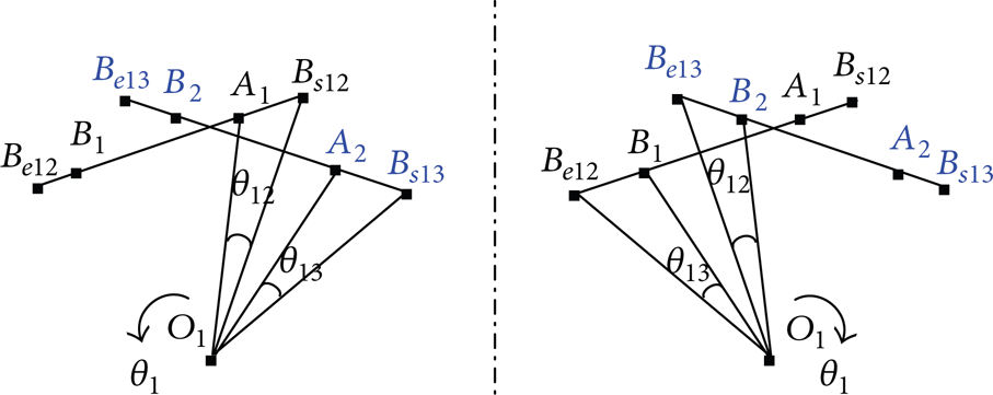
The analysis method based on symmetry.
When gear g1 rotates in reversal from θ1 = 0, in order to make full use of the calculation formulas of each meshing point in positive rotation, the 4 meshing points are replaced by each other: as shown in Figure 6, B2, A2, B1, and A1 are replaced by A1, B1, A2, and B2 separately; in the same way, the meshing stiffness of meshing points is replaced as km13B2, km13A2, km12B1, and km12A1 are replaced by km12A1, km12B1, km13A2, km13B2 separately. For example, the position of meshing point A2 can be determined by given θ13 in positive rotation, and according to the analysis method based on symmetry, the position of B1 in reversal can be determined at the same time.
By the above analysis, the position in double-tooth or single-tooth meshing area of gear pair g1g2 or g1g3 in reversal can be determined by the means of that used in positive rotation.
4.4. Dynamic Equations
4.4.1. Positive Rotation
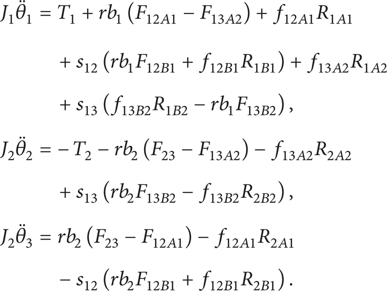
As shown in Figure 7, according to the Newton' second law, assuming the antibacklash gear satisfying the conditions in (9a) and (9b), the dynamics equations of the antibacklash gear in different meshing areas are written as (16a)–(16d).

Pure torsional model of antibacklash gear (positive rotation).
When θ12 < θ c and θ13 < θ, both gear pairs g1g2 and g1g3 are in double-tooth meshing area (DMA). Here,

When θ12 < θ c and θ13 ≥ θ c , gear pair g1g2 is in DMA, and g1g3 is in single-tooth meshing area (SMA), while

When θ12 ≥ θ c and θ13 < θ c , gear pair g1g2 is in SMA, and g1g3 is in DMA while

When θ12 ≥ θ c and θ13 ≥ θ c , both gear pairs g1g2 and g1g3 are in SMA. Here,

where J i is the moment of inertia of gi; θ i is the angle of rotation of gi; T i is the load moment. The other variables are defined in Appendix C.
In order to simplify these equations, a switch function is defined as
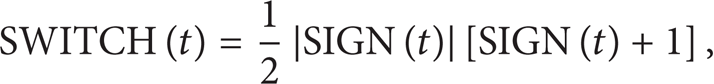
where SIGN (t) is the signum function, and

Therefore, the equations above can be simplified and composited as

By further derivation,

where s12 = SWITCH (θ c – θ12); s13 = SWITCH (θ c – θ13).
Let

Equation (4) can be transformed to a normalized matrix equation as

here,

Coefficients of matrix equation are written in Appendix D.
4.4.2. Reversal
As shown in Figure 8, in reversal, the contact forces in meshing points are replaced by the method mentioned in Section 4.3. In other words, the forces F12B1, F12A1, F13A2, and F13B2 in reversal are, respectively, replaced by F13A2, F13B2, F12B1, and F12A1 calculated in positive rotation. So, the dynamic equations of mechanism are written as follows:

Purely torsional model of antibacklash gear (reversal).
By further derivation,

The normalized matrix equation of (25) is written as

here,
By simplification and compared with the matrix equation in positive rotation, the matrix elements are expressed as follows:
5. Numerical Calculation and Discussion
In order to calculate and discuss the characteristics of antibacklash gear, an antibacklash gear, the parameters of which are shown in Table 1, is taken as an example. The numerical calculation model is established in Matlab/simulink with the algorithm of fifth-order Runge-Kutta and fixed-step of 0.00001 s.
Parameters of antibacklash gear.

5.1. Basic Characteristics
Antibacklash gear is widely used for precision mechanisms to reduce transmission error, especially backlash. figures from Figure 9 (a) to Figure 9 (c) show the meshing stiffness of gear pairs g1g2 K1, g1g3 K2 and the composite meshing stiffness K s , respectively. As shown in Figure 10, broken line represents the stiffness curve of antibacklash gear, and the solid line represents normal gear pair with the same parameters, reversal at 0.0 s. Curves show that the composite meshing stiffness of antibacklash gear is larger than that of normal gear pair, and the backlash is eliminated in antibacklash gear.
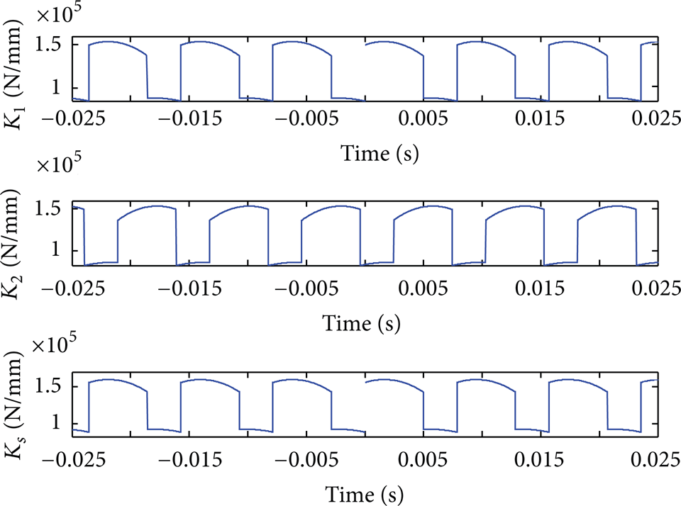
Meshing stiffness of gear pair g1g2 K1, g1g3 K2 and composite meshing stiffness K s with reversal at 0.00 s.
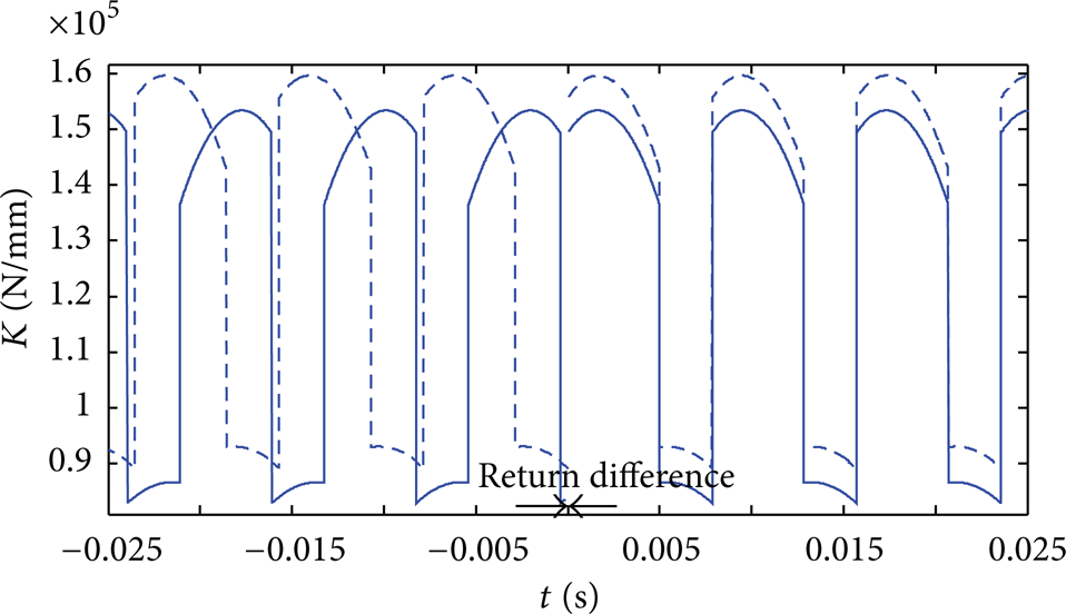
Meshing stiffness of antibacklash gear compared with normal gear pair. Key: – antibacklash gear, — normal gear.
5.2. Effect of Friction and Damping Ratio
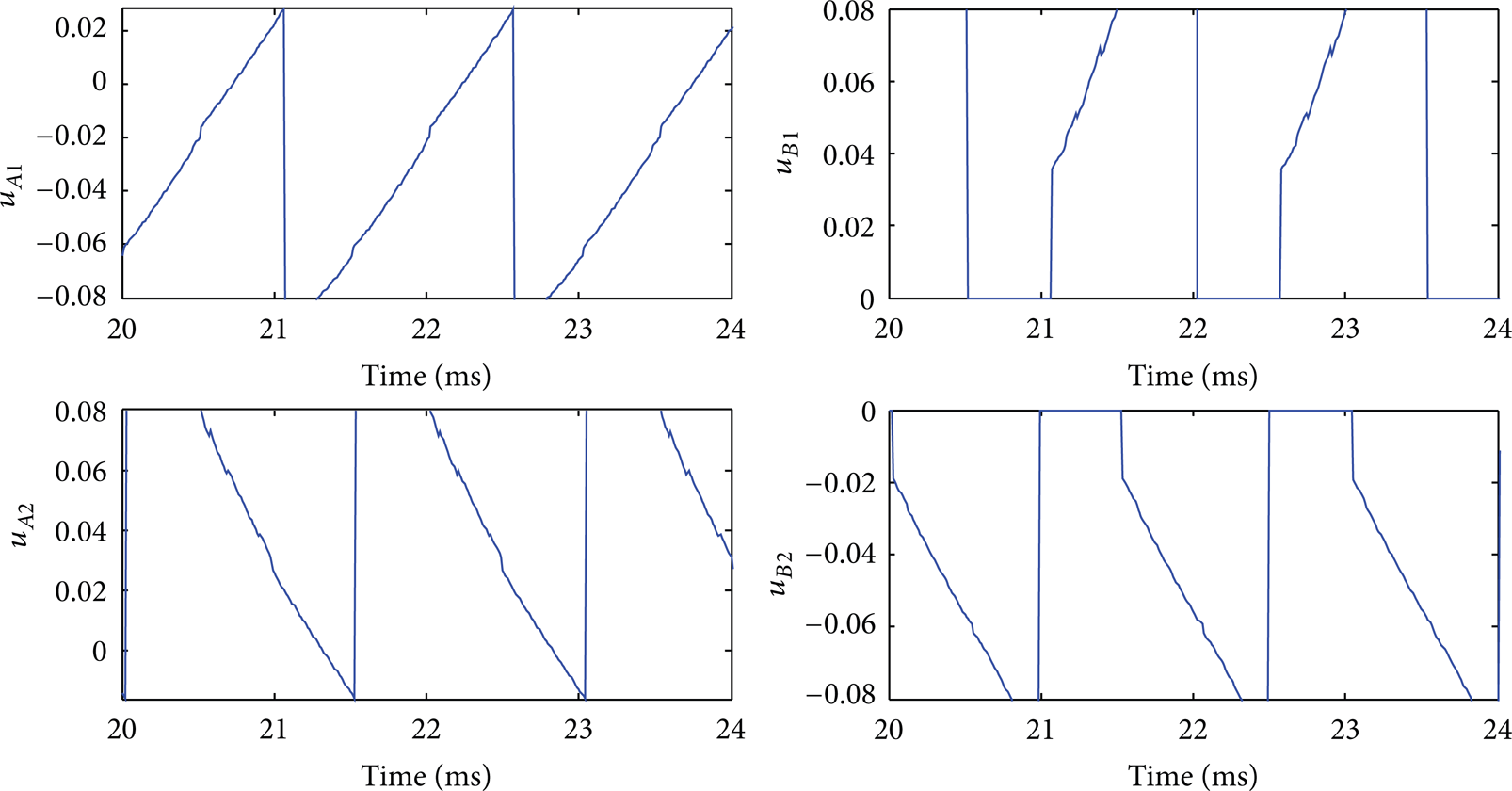
In the paper, the elastohydrodynamic lubrication (EHL) regime is assumed, and Dowson's formula of instantaneous coefficient of friction is adopted. The calculation formulas of friction and coefficient of friction are written in Appendix B. In Figure 11, instantaneous coefficient of friction μ at initial rotation speed 1000 rpm, T1 = 100 N·mm, and T2 = 200 N·mm is shown. In Dowson's semirational formula, μ is limited in a range of [−0.08, 0.08], According to the range, when the coefficient of friction beyond 0.08, the coefficient of friction is equal to 0.08, and when the coefficient of friction beyond −0.08, the coefficient of friction is equal to −0.08. And μ = 0 at the pitch point, the farer meshing point is away from pitch point, the larger the absolute value of μ is. Figure 12 shows the curves of normal load, friction, and coefficient of friction at meshing point A1 for 200 rpm and ζ = 0.08. From Figure 12, we can find out the pitch point of g1g2 at the point where μ = 0. And the position is the same as the position where the pitch point of g1g2 appears in Figure 13.
Coefficients of friction at each meshing point for 1000 rpm.
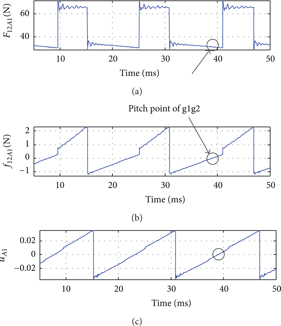
Normal load, friction, and coefficient of friction at point A1 for 200 rpm, ζ = 0.08.
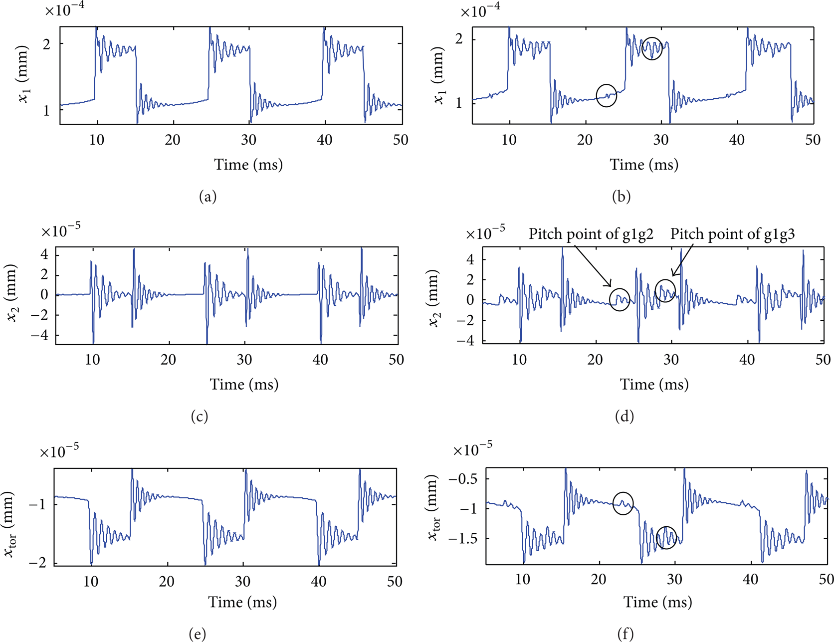
Dynamic response x1, x2, and xtor for 200 rpm, ζ = 0.08.
The dynamic responses x1, x2, and xtor of g1g2, g1g3, and g2g3 are shown in Figures 13 and 14. In Figures 13 (a), 13 (c), 13 (e), 14 (a), 14 (c), and 14 (e), there is no sliding friction and the only excitation is caused by the sudden changes in meshing stiffness. On including friction, as shown in Figures 13 (b), 13 (d), 13 (f), 14 (b), 14 (d) and 14 (f), additional impulsive effects are observed at the pitch points of gear pairs g1g2 and g1g3 where the μ changes its sign.
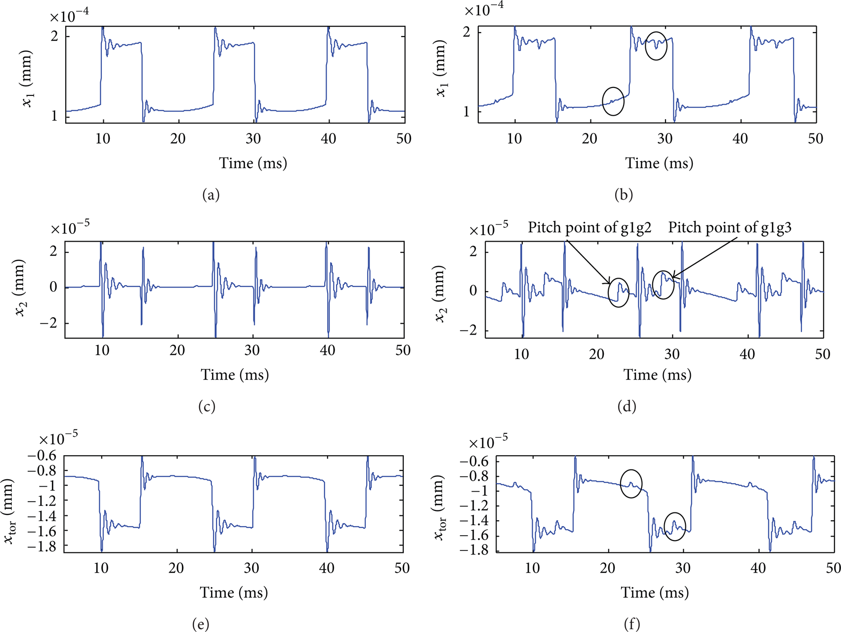
Dynamic response x1, x2, and xtor for 200 rpm, ζ = 0.2.
The other effect of friction is the reduction of rotation speed due to energy attenuation, which is more significant than that of damping. As shown in Figure 15, the declining curve represents the rotation speed of g1 with friction at the initial rotation speed of 2000 rpm, ζ = 0.08, no drive, and load torque. It shows that the rotation speed of g1 will be gradually close to zero under only the action of friction.

Rotation speed of g1 for initial rotation speed of 2000 rpm, ζ = 0.08.
This characteristic can also be observed from the frequency spectrum of dynamic response x1, x2, and xtor. In Figures 17 (b), 17 (d), and 17 (f), the width of frequency band in the same value of center frequency is wider than that in Figures 16 (b), 17 (d), and 17 (f) without friction, and the amplitude is lower. That is because as the rotation speeds reducing, the period of the response signal becomes longer, which leads the frequency band width wider, and the frequency resolution decreasing. All of these are mainly due to friction.

Rotation speed of g1 for initial rotation speed of 2000 rpm, ζ = 0.08, without friction, no drive torque, and load torque.

Rotation speed of g1 for initial rotation speed of 2000 rpm, ζ = 0.08, with friction, no drive torque and load torque.
In addition, in Figures 13 and 14, damping ratios ζ = 0.08 and ζ = 0.2, respectively. Obviously, damping ratio can reduce the vibration and impact due to gear pairs meshing in and out.
5.3. Effect of Torsional Spring Stiffness and Preload
The RMS of the DTE and the oscillating components of the DTE at a specific constant rotation speed (2000 rpm in this study) are defined as [20]

where DTE i represents one variable of x1(t i ), x2(t i ), and xtor(t i ); N is the total number of time steps.
Figures 18–20 show the effects of torsional spring stiffness and preload on the ODTE and RDTE, and line style -Δ- represents the g1g2; -*- represents the g1g3; -○- represents the g2g3. In Figure 18, as the torsional spring stiffness increases from 1E + 03 to 1E + 09 N·mm/rad, both ODTE and RDTE of g1g2 and g1g3 decrease except ODTE of g2g3, but when the torsional spring stiffness is large enough, greater than 2.6E + 06 N·mm/rad, the ODTE and RDTE trend to be a constant value, respectively. As shown in Figure 21, the increase of equivalent linear stiffness k x of torsional spring stiffness to line of action leads to the increase of composite meshing stiffness of antibacklash gear mechanism, which may be the reason why ODTE and RDTE of g1g2 and g1g3 decrease. The DTE of g2g3 xtor depends on the difference of x1 and x2; thus, there may be no direct relationship between composite meshing stiffness and ODTE of g2g3, which deserves further study.
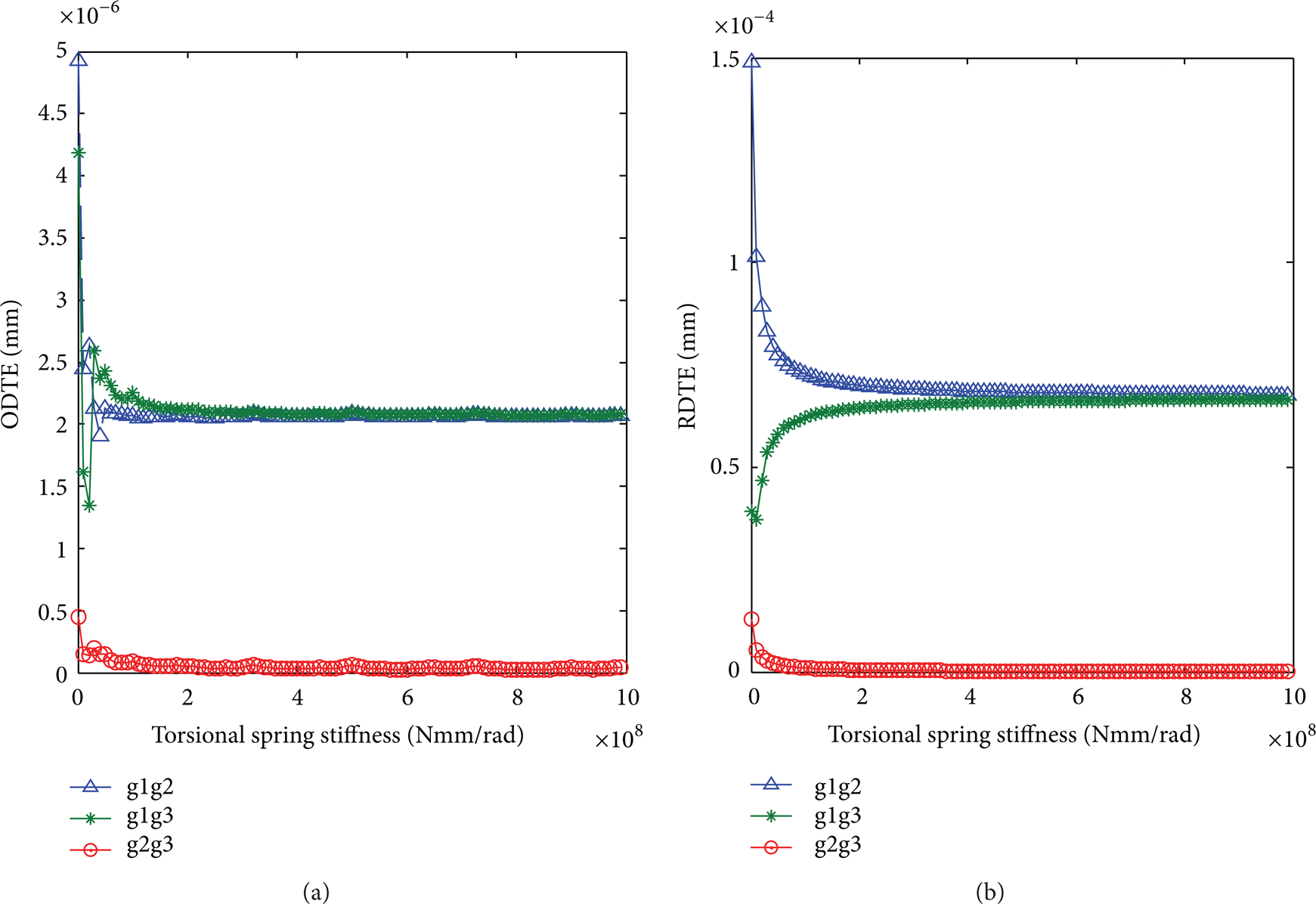
Variations of ODTE and RDTE for ktor ∊ [1E + 03,1E + 09] N·mm/rad, Tpre = 1000 N·mm, ζ = 0.08, with friction.

Variations of ODTE and RDTE for ktor = 1E + 05 N·mm/rad, Tpre ∊ [1, 1E + 05] N·mm, ζ = 0.08, with friction.

Variations of ODTE and RDTE for ktor = 1E + 05 N·mm/rad, Tpre ∊ [1, 1E + 05] N·mm, ζ = 0.08, without friction.
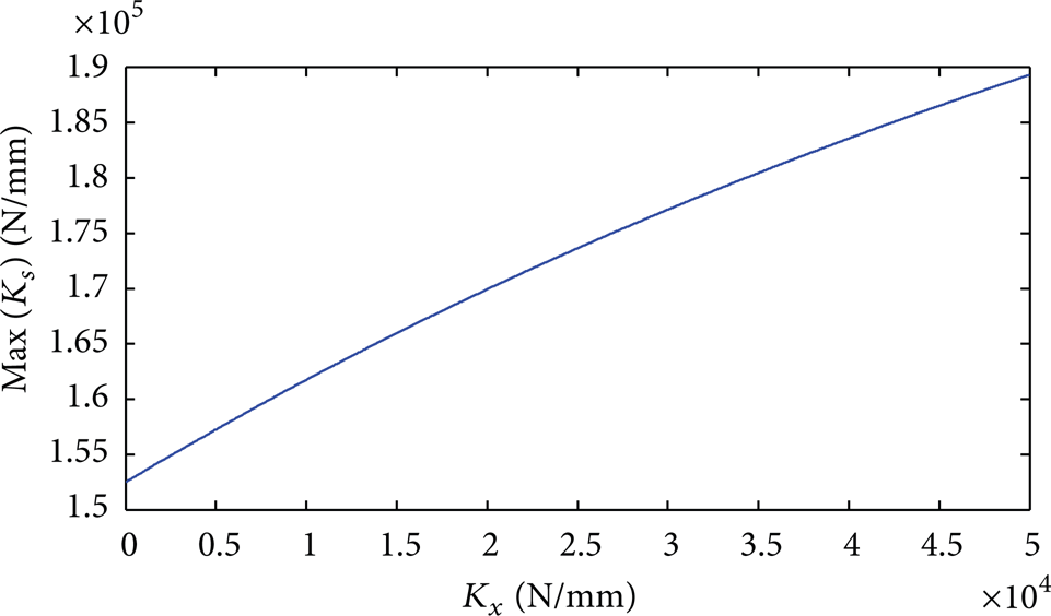
Relationship between torsional spring equivalent linear stiffness and the max composite meshing stiffness.
Preload of torsional spring is essential to eliminate the backlash of gear pair. However, if the preload is too small, the backlash will not be eliminated completely; if the preload is too large, friction between two meshing gears will become large due to the increase of normal load. As shown in Figure 18, when preload is less than a certain value, about 2E + 04 N·mm, the changes of ODTE and RDTE are not significant, but when exceeding that range, the ODTE and RDTE increase rapidly. Figure 20 shows the ODTE and RDTE without friction for Tpre ∊ [1, 1E + 05] N·mm. The ODTE and RDTE basically unchanged. Thus, friction is the reason. The increase of friction causes the increase of the ODTE and RDTE, while the increase of the preload makes the increase of friction.
6. Conclusions
According to the meshing characteristics of antibacklash gear mechanism, the single- or double-tooth meshing state of two gear pairs was determined. A time-vary meshing stiffness model based on tooth bending stiffness per unit width and Hertz contact stiffness and Dowson's coefficient of friction at each meshing point were applied in antibacklash gear mechanism, which improved the model accuracy of gear system, and also was a new application on modeling of double-gear antibacklash mechanism. The proposed kinetic model with time-vary parameters will be useful for further study on dynamic characteristics such as vibration and noise of antibacklash gear and some precision transmission mechanism with antibacklash gear. Some results were obtained by numerical calculations and simulations. (a) The composite meshing stiffness of antibacklash gear is larger than that of normal gear pair, and increasing the torsional spring stiffness can increase the composite meshing stiffness. (b) Friction leads to degradation of energy and impulses at the pitch points where the coefficients of friction change their signs. (c) Damping ratio plays a significant role in the suppression of the vibration and impact due to gear pairs meshing in and out. (d) Within a certain range, increasing the torsional spring stiffness can reduce the ODTE and RDTE except ODTE of g2g3, which deserves a further study, but when the torsional spring stiffness is large enough, the ODTE and RDTE trend to be a constant value. (e) Preload of torsional spring is important to ODTE and RDTE, and when preload is less than a certain value, the variations of ODTE and RDTE are not significant.
Footnotes
Appendices
Acknowledgment
This work was supported by the National Natural Science Foundation of China (Grant no. 51175505).