
Abstract
Impingement cooling has been widely employed to cool gas turbine hot components such as combustor liners, combustor transition pieces, turbine vanes, and blades. A promising technology is proposed to enhance impingement cooling with water droplets injection. However, previous studies were conducted on blade shower head film cooling, and less attention was given to the transition piece cooling. As a continuous effort to develop a realistic mist impingement cooling scheme, this paper focuses on simulating mist impingement cooling under typical gas turbine operating conditions of high temperature and pressure in a double chamber model. Furthermore, the paper presents the effect of cooling effectiveness by changing the mass and size of the droplets. Based on the heat-mass transfer analogy, the results of these experiments prove that the mass of 3E – 3 kg/s droplets with diameters of 5–35 μm could enhance 90% cooling effectiveness and reduce 122 K of wall temperature. The results of this paper can provide guidance for corresponding experiments and serve as the qualification reference for future more complicated studies with convex surface cooling.
1. Introduction
Efficiency is one of the most important parameters in evaluating the performance of a gas turbine engine. With even a 1% efficiency increase, the operating costs can be substantially reduced over the life of a typical power plant. One of the most effective ways to improve the gas turbine system efficiency is to increase the combustor outlet temperature. A higher outlet temperature leads to better system thermodynamic efficiency. However, outlet temperature is limited by the highest temperature that the material of the gas turbine can withstand. Spontaneously, we need to consider the efficiency of cooling technology which plays a significant role in the whole process as the more efficiency it applied, the higher temperature of combustor could exit and the efficiency of gas turbine cycle could reach. Cooling technology has been successfully applied in protecting turbine airfoils from high temperature since the last half century [1, 2]. The majority of the literature has been covered in the book by Han et al. [3]. Such that most of these studies concentrate on blade shower head film cooling; however, less attention is given to the transform piece cooling [4]. As one of most important cooling technology, impingement cooling has been studied on transform piece cooling.
The early investigation on impingement cooling has been summarized by Chupp et al. [5]. They did experimental study on impingement of a single row of circular jets on semicircular concave surface. Their results suggested general increases in heat transfer with approximately the 0.7 power of jet Reynolds number. Dyban and Mazur [6] measured heat transfer coefficient on a parabolic concave surface and investigated the effect of jet flow passage curvature. McCormack et al. [7] found that Nusselt numbers were increased by 100–150% on the concave surface. Hrycak [8] proposed correlations for stagnation and average heat transfer coefficient for a row of impinging jets on a cylindrical concave surface. Wei et al. [9] investigated impingement and serpentine convection cooling under the effect of rotation. Their results suggested that rotation effects increase the serpentine cooling and reduce the jet impingement cooling.
As the working gas temperature continuously increases to augment thermal efficiency, new cooling techniques are needed to surpass incremental improvements of conventional gas turbine cooling technologies. A promising technology is to enhance film cooling with mist (small water droplets) injection. Based on the aforementioned heat transfer mechanisms, mist can be used in gas turbine systems in different ways, including gas turbine inlet air fog cooling [10], overspray cooling through wet compression in the compressor [11], and airfoils (vanes and blades) internal cooling [12–16]. Recently, Li and Wang [17] conducted the first numerical simulations of air/mist film cooling. They showed that injecting a small amount of droplets (2% of the coolant flow rate) could enhance the cooling effectiveness about 30–50%. Li and Wang [18] continued a more fundamental study on investigating the effect of various models on the computational results including the turbulence models, dispersed phase modeling, different forces models (Saffman, thermophoresis, and Brownian), trajectory tracking model, near-wall grid arrangement, and mist injection scheme.
As a continuous effort to develop a realistic impingement cooling scheme, this paper focuses on using a promising technology to enhance impingement cooling which is to inject water mist into the coolant flow. The main objective of this thesis is to elucidate how the mass and dimension of the droplet affect the mist impingement cooling performance over a curved surface with a hole of double chamber model, calculated by CFD. Earlier studies discussed the mist film performance on the blade and combustor of gas turbine [10–15]. The model created in the paper looks like a flat with two double chambers, simulating the structure of transition piece. Accordingly, the main objectives of the investigation are as follow: (1) model establishment: discrete-hole impingement cooling flat surface with an injection coolant intercalation; (2) model analysis: the droplet mass ratio and dimension on mist impingement cooling effectiveness over a flat surface; (3) results comparison: the temperature of inner wall, film cooling effectiveness, velocity magnitude contours, and droplet particle track in various conditions. The results of this paper can serve as a reference for future experimental validation and technical implementation to real gas turbine applications.
2. Numerical Method
The new transition piece features a rounded body shape that balances the heat transfer loading both internally and externally and eliminates resonant frequency concerns [19], which consists of heavier walls, single-piece aft ends, ribs, seal arrangements, and selective cooling. It has an upstream aperture for the gas flow (which is cylindrical), and it is used to receive the gas flow directly from the corresponding combustion liners with a high level of enthalpy; transition pieces are conjured in a longitudinal direction so that their downstream ends comprise arched segments to form a ring-type configuration which opens toward the first stage of the gas turbine (stator) [20, 21].
A schematic of the flow domain along with boundary conditions and dimensions is given in Figure 1. As shown in the figure, the flat model has two chambers with length of 1050 mm, and the outer and inner height is 38 mm and 162 mm, respectively. The outer chamber in Figure 1 is called coolant chamber as the side is closed. Contrarily, the inner chamber goes by the name of mainstream chamber as the gas could pass through it from one side to another. There is a hole on the surface of the outer wall, and the distance from the hole to the end of the model is 520 mm. The size of all the holes is about 10.26 mm.

Computational domain showing boundary conditions.
2.1. Turbulence Model (Realizable k-∊)
The present film cooling study involves flow which is steadied, Newtonian, three-dimensional, incompressible, and turbulent. Such flow behaves according to three fundamental laws, namely, the laws of continuity, conservation of momentum, and conservation of energy.
The realizable k-∊ model proposed by Shih et al. [22] was intended to address these deficiencies of standard k-∊ models by adopting the following: (1) realizable k-∊ model contains a new formulation for the turbulent viscosity; and (2) a new transport equation for the dissipation rate, ∊, is derived from an exact equation for the transport of the mean square velocity fluctuation. The modeled transport equations for k and ∊ in the realizable k-∊ model are

where
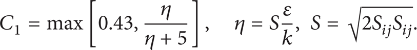
In these equations, G k and G b represent the generation of turbulent kinetic energy due to the mean velocity gradients and buoyancy, respectively. Y M is the contribution of the fluctuating dilatation in compressible turbulence to the overall dissipation rate, and C1∊ and C2 are constants. S k and S∊ are user-defined source terms. The turbulent (or eddy) viscosity μ t is computed by combining k and ∊ as follows:

A benefit of the realizable k-∊ model is that it better predicts the spreading rate of both planar and round jets. It is also stated that it has superior performance for flows involving rotation, separation, recirculation, and boundary layers under adverse pressure gradients.
2.2. Stochastic Particle Tracking
To track the trajectory of droplets, the hydrodynamic drag, gravity, and forces such as the “virtual mass” force, thermophoretic force, Brownian force, and Saffman's lift force are combined to accelerate the droplet. The energy equation for any individual droplet can be given as the following equation:
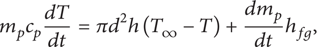
where h fg is the latent heat. The convective heat transfer coefficient (h) can be obtained with an empirical correlation [23, 24].
The mass change rate or vaporization rate in (4) is governed by concentration difference between droplet surface and the air stream:

where k c is the mass transfer coefficient and C s is the vapor concentration at the droplet surface, which is evaluated by assuming that the flow over the surface is saturated. C∞ is the vapor concentration of the bulk flow, obtained by solving the transport equations. When the droplet temperature reaches the boiling point, the following equation can be used to evaluate its evaporation rate [25]:
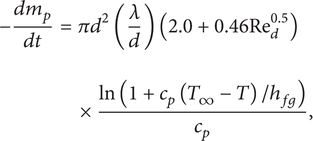
where λ is the gas/air heat conductivity and c p is the specific heat of the bulk flow.
Stochastic method [26] is used to consider turbulence dispersion effect on droplets tracking. The droplet trajectories are calculated with the instantaneous flow velocity (

where ς is a normally distributed random number. This velocity will apply during the characteristic lifetime of the eddy (t e ), a time scale calculated from the turbulence kinetic energy, and dissipation rate. After this time period, the instantaneous velocity will be updated with a new ς value until a full trajectory is obtained.
2.3. Boundary Conditions
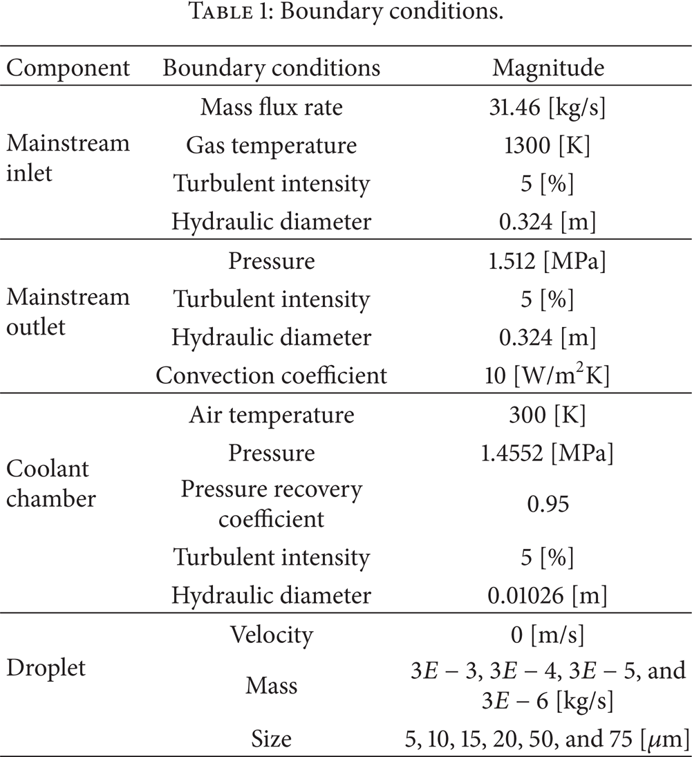
Boundary conditions were applied to specific faces within the domain to specify the flow and thermal variables that dictate conditions within the model. They are a critical constituent to the simulation, and it is important that they are specified appropriately. The masses of water droplets are 0, 3E – 6, 3E – 5, 3E – 4, and 3E – 3 kg/s. The droplet size is given as 5, 15, 25, 35, 45, and 55 μm.
Figure 1(a) also shows the boundary conditions used for the modeling. Respectively, the cooling air and gas are coursing along the cooling chamber and the mainstream chamber with the opposite direction. In the cooling chamber, the simulation is performed using air as the cooling flow; velocity and temperature contours are set on the jet holes, and then out from the exit mouth. In another chamber, assume that the mainstream is a mixture of O2, H2O, CO2, N2, and some rare gas. Gas velocity and temperature contours are set on the surface of the sector section; pressure on the exit mouth and natural convection on the outside wall of the model are considered as boundary condition (Table 1) [4]. In gas chamber, egress of the mainstream was fixed and exported free expansion. The assumption of the solid wall of the quarter torus is modeled with a hypothesis of negligible thermal resistance by conduction; the thermal properties of the material were considered by Nimonic 263. The temperature of the coolant and mainstream flow are set as 300 K and 1300 K, respectively.
Boundary conditions.
2.4. Mesh and Simulation Procedures
The computational domain incorporates the model, the HEXA mesh in the software, ICEM/CFD, used to generate the structured multi-block and the body-fitted grid system. This software allows to separate grids generated for different parts of the flow domain, using an appropriate grid system. In this study, the grid system associated with the parts of the mainstream and the coolant supply plenum is H-type. Figure 2 shows the grids of the computational domain. The total number of the cells for the 3D domain is 198,068.

Mesh.
This study uses a commercial CFD code based on the control-volume method, ANSYS-FLUENT 12.0.16, which in order to predict temperature, cooling effectiveness, velocity fields, and droplet particle track at different droplet mass and size. All runs were made on a PC cluster with four Pentium-4 2.8 GHz personal computers. The convergence criteria of the steady-state solution are judged by the reduction in the mass residual by a factor of 6, typically, in 2000 iterations.
3. Result and Discussion
In this section, the results obtained with a different mass ratio and dimension of droplet are presented in order to validate the CFD model above so that the mist impingement cooling physics would be well studied.
3.1. Effect of Droplet Mass
Comparison of the temperature and cooling effectiveness results of four droplet masses (3E – 3, 3E – 4, 3E – 5, and 3E – 6 kg/s) is shown in Figure 3. In this condition, the size of all droplets is 5 μm. Similar to the results under high pressure and temperature conditions [4], the heavier droplets are shown to provide better enhancements. The figure illustrates that the temperature at the starting point of the wall is high, and then it starts to go down. The starting point is cooled by the coolant holes at the Z = 525 mm on the outer wall, while the same temperature is maintained throughout the coolant hole. With the droplet mass increase, the color of temperature distribution in the same region becomes lighter which indicates that the surface has been better protected by the coolant flow. Since the jet flow seems to possess sufficient capacity to receive more mist flow, it is interesting to see the effect of injecting more mist into the jet flow.

Comparative analysis of temperature and cooling effectiveness at different droplet masses (no droplet, 3E – 6, 3E – 5, 3E – 4, and 3E – 3 kg/s) showing vortex induction towards the inner wall and (a) temperature distribution of inner wall and (b) cooling effectiveness distribution.
The adiabatic cooling effectiveness (η) is used to examine the performance of film cooling. The definition of η is
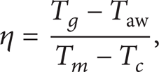
where T g is the mainstream hot gas inlet temperature, which is a fixed value for calculation of the adiabatic cooling effectiveness of any location, and T c is the temperature of the coolant, which is assigned as a constant of 300 K in this issue. Taw is the adiabatic wall temperature.
The cooling effectiveness is defined the same as it was in the previous section. To evaluate the cooling enhancement of adding mist into the air film, the net enhancement is plotted on the secondary y-axis on the right-hand side. The net enhancement is defined as follows:

The subscript “m” means mist is added. Without any subscript, it means air-only film is used. From the definition, net enhancement is zero if the mist cooling effectiveness is the same as the air-only cooling effectiveness.
Note that mist film cooling itself can be improved by using different droplet masses. Figure 4 shows the cooling effectiveness and enhancement ratio when different droplet masses are employed. For simplicity, it can be seen that when the droplet mass is 3E – 6 kg/s, the adiabatic cooling effectiveness increases significantly. Compared with the normal case, the cooling effectiveness of MIC provides 90% in axis Z = 550 mm. The cooling effectiveness lines are almost the same with no MIC case condition when the droplet mass is 3E – 6, 3E – 5, and 3E – 4 kg/s. Therefore, it is plausible that the temperature and cooling effectiveness contours of lighter mass cases (3E – 6, 3E – 5, and 3E – 4 kg/s) are similar to the no MIC case.
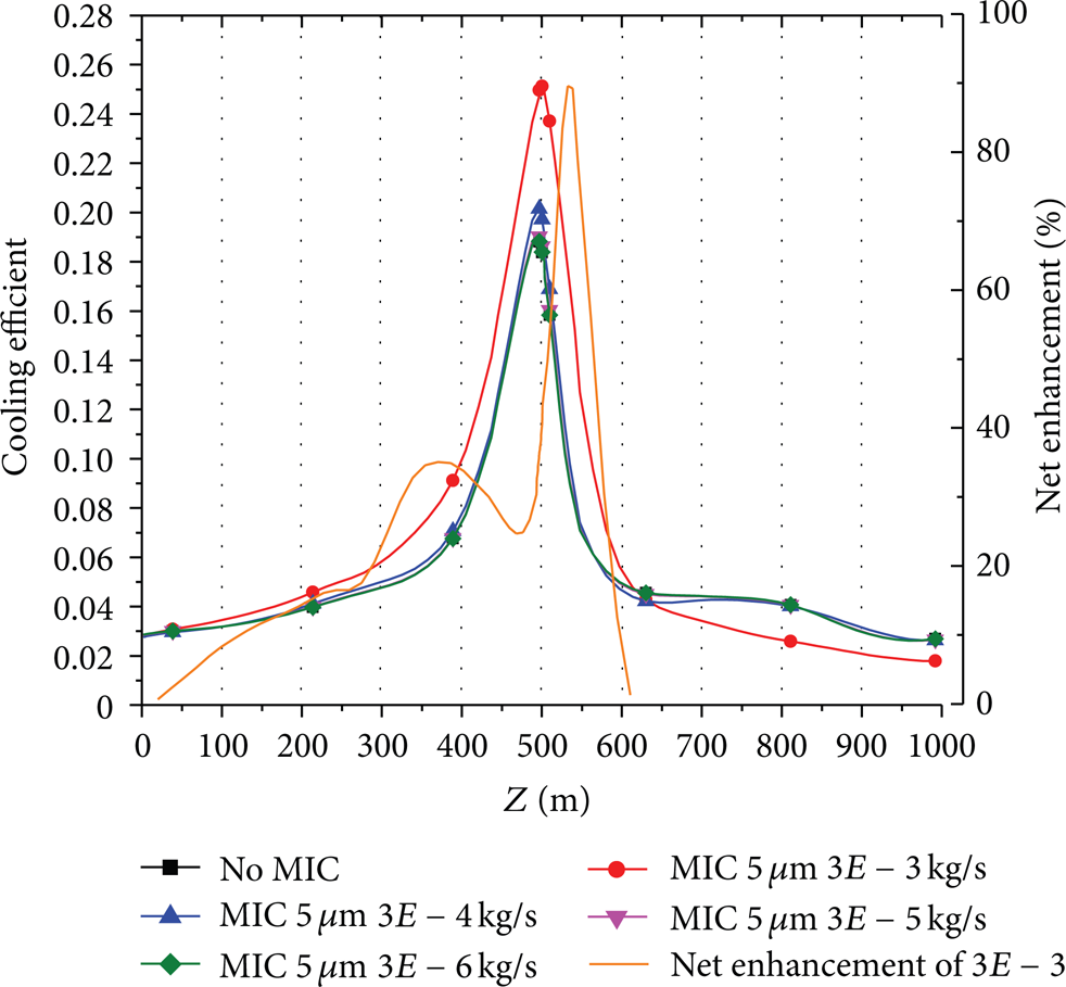
Distributions of averaged cooling effectiveness and net enhancement of 3E – 3 kg/s in the different droplet masses.
3.2. Effect of Droplet Size
In real applications, the size of droplet is another factor that could affect the mist impingement cooling results. Comparison of the cooling effectiveness in different sizes (5, 15, 25, 35, 45, and 55 μm) with 3E – 3 kg/s droplet mass is shown in Figure 5. In the picture, the cooling effectiveness lines are almost the same when the droplet size is 5, 15, 25, and 35 μm. However, the cooling effectiveness is reduced by increasing the droplet size (45 and 55 μm), and they all have the same trend with the normal case. Before axis Z = 600 mm, the smaller droplets are shown to provide better enhancements. The small droplets provide higher surface to volume ratio, so evaporation completes more rapidly and effectively than the larger droplets. The results show that its effect on cooling effectiveness is negligible because the size is found very large (larger than 35 μm) in the currently studied cases.
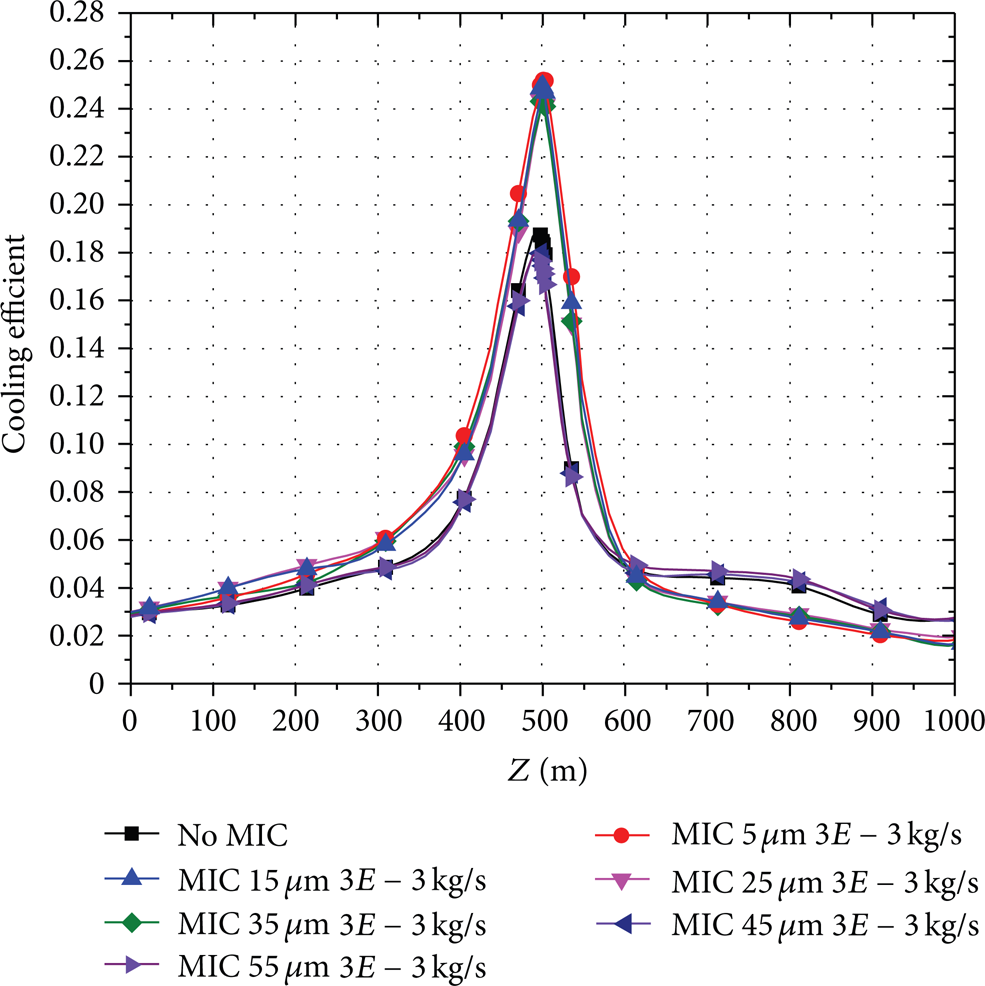
Distributions of averaged cooling effectiveness in different sizes with 3E – 3 kg/s droplet mass.
Figure 6 shows the velocity magnitude contours and the droplet particle track in the different size cases. Figure 6(a) shows that the droplets impact the inner wall, which moved with the coolant jet from the hole. In the small size cases (5, 15, 25, and 35 μm) of Figure 6(a), all the droplets evaporate before axis Z = 600 μm in the coolant chamber. However, larger droplets may exit the computational domain without complete evaporation due to low evaporation rate or short residential time. Therefore, it is plausible that the large droplets move farther away from the wall than small droplets under the condition in the current study due to the high inertia force from jet injection. This mechanism of larger droplets moving further away from the wall contributes to ineffectiveness of producing film cooling protection of the inner wall even though the latent heat absorption can reduce the coolant chamber temperature.

Distributions of velocity magnitude contours and droplet particle track in different sizes with 3E – 3 kg/s droplet mass: (a) droplet particle track and (b) velocity vector plot.
To explain the effect of droplet size on MIC enhancement with flat configuration, velocity vectors at the coolant chamber are plotted and shown in Figure 6(b). The figure shows that the small size cases (5, 15, 25, and 35 μm) jet velocity vectors are much shorter in the coolant chamber than large size cases (45 and 55 μm). The small size cases jet is formed as the impinging jet turning parallel to the surface from the stagnation region. Due to jet-to-jet interaction after impingement, the flow becomes complex with a large 3D recirculation zone in the large size cases. Corresponding to the large recirculation zone, the droplet particle track of the large size cases offsets to one side of coolant chamber.
4. Conclusion
A complete three-dimensional numerical simulation of a mist impingement cooled flat double chamber model is conducted to study coolant structure, and it has been proven that this structure could be influenced by the droplet mass and size. This feature is very favorable in considering applying mist impingement cooling in the transition piece because of the following.
The liquid droplets in the film provide a more extended impingement cooling coverage effect than the air impingement cooling.
Compared with no MIC case, the maximum enhancement of adiabatic cooling effectiveness is about 90% for the 3E – 3 kg/s droplet mass case, corresponding to an additional adiabatic wall temperature reduction of 122 K.
Smaller size droplets (5, 15, 25, and 35 μm) provide 80–90% better cooling performance than larger size droplets (45 and 55 μm).
Footnotes
Nomenclature
Conflict of Interests
The authors declare that they have no conflict of interests.
Acknowledgments
This research is supported by the Technology Development of Jilin Province (no. 20126001), Key Technologies R&D Program of Changchun (no. 10KZ03), and the National Natural Science Foundation of China (no. 51205159).