
Abstract
Magnetic gear trains transmit torque through noncontact magnetic couplings rather than conjugate gear teeth; they have the unique advantages of reduced maintenance and improved reliability, inherent overload protection, high efficiency, precise peak torque transmission, and tolerance for misalignment. Smooth and steadily transmitted torque is an important characteristic for a magnetic gear train. It is necessary for the reduction of possible mechanical vibration, position inaccuracy, and acoustic noise. This paper investigates the transmitted torque characteristics, especially torque ripple reduction, of an external-meshed magnetic gear train using finite-element analysis (FEA). The topological structure and working principles of a simple magnetic gear train with parallel axes are introduced. With the aid of a commercial FEA package, the transmitted torque waveform of a magnetic gear train is numerically calculated. The effects of geometrical parameters on the maximum transmitted torque and torque ripple are further discussed in terms of obtaining a magnetic gear train with high transmitted torque or low torque ripple. This examination offers insights beneficial to future magnetic gear mechanism design.
1. Introduction
A traditional gear is a mechanical component with a conjugate tooth profile. It is commonly used in the transmission systems of industrial machines. Two or more meshing mechanical gears form a gear train (or a gear mechanism) that transmits power from one rotating shaft to another. In addition to transmitting power, gear trains are often employed to increase or reduce speed or change the direction of motion from one shaft to the other. Mechanical gear mechanisms have significant advantages when dealing with high torque densities and have high reliability; however, they require lubrication, cause mechanical impact, generate noise and vibration, and result in low mechanical efficiency due to friction. Permanent magnets offer new opportunities as alternatives to mechanical gears. Noncontact magnetic gears have been developed to overcome the inherent drawbacks associated with mechanical gears. Magnetic gears transmit torque between the input and output shafts by magnetic coupling rather than by the use of conjugate gear teeth. Therefore, no mechanical contact and wear exist in a magnetic gear train; transmission oil for lubrication and cooling is no longer required. Compared to mechanical gears, magnetic gears offer unique advantages. These advantages include reduced maintenance and improved reliability, inherent overload protection, high efficiency, precise peak torque transmission, tolerance for misalignment, and physical isolation between the input and output shafts. Due to these features, magnetic gear mechanisms have been attracting increasing attention from commercial organizations and academic institutions. Although magnetic gear mechanisms with different kinematic structures have been proposed [1–6], a common drawback of these devices is inherent torque ripple on the output shaft, which induces speed fluctuation. Because the driving magnetic gear rotates at a constant angular speed, the driven magnetic gear continuously accelerates and decelerates. This may result in undesirable cyclic stress, mechanical vibration, position inaccuracy, acoustic noise, and other problems [7]. It is detrimental to the output performance and lifetime of a magnetic gear mechanism, particularly at low speed or high-precision position and motion control applications. In recent years, the suppression of torque ripple has become an essential task for engineers when designing a magnetic gear mechanism. In 2009, Frank and Toliyat designed a concentric planetary type magnetic gear mechanism for the high-torque, low-speed requirements of a wind turbine [8] and a marine propulsion system [9]. Such a concentric configuration was originally proposed by Atallah and Howe [10]. Frank et al. discussed the effects of gear ratios on the torque ripple of the concentric magnetic gear mechanism. His work shows that a higher value of the least common multiple of the numbers of magnet pole pairs for high-speed rotor and steel pole-pieces will result in less torque ripple when the frame of steel pole-pieces is stationary. A higher gear ratio will naturally have a higher least common multiple, which will result in a higher torque ripple fundamental order and a lower torque ripple percentage. Jian et al. [11] quantitatively compared two coaxial magnetic gears with radially and Halbach magnetized magnets by using a 3-dimensional finite-element analysis (FEA). They showed that a coaxial magnetic gear with Halbach magnetized magnets offers higher transmitted torque, lower torque ripple, and lower iron losses than one with radially magnetized magnets. In 2010, they also formulated magnetic field distributions within the inner and outer air gaps, while the magnetic torque and torque ripple of the coaxial magnetic gear were analytically derived [12]. A novel magnetic harmonic gear with a high gear ratio that transmits a ripple-free torque was proposed by Rens et al. [13]. An active transmitted torque density of up to 150 kNm/m3 was achieved when high-energy permanent magnets were employed. In 2012, Niguchi and Hirata [14] described the harmonic spectra of the cogging torque of a coaxial magnetic gear mechanism where permanent magnets were mounted on the outer surface of the high-speed rotor and on the inner surface of the low-speed rotor. The cogging torque on each rotor was discussed. They also coaxially combined a high-speed rotor with permanent magnets, a low-speed rotor with steel pole-pieces and a stator consisting of laminated magnetic sheets and concentrated windings to form a compact magnetic-geared motor [15]. The torque characteristics and the order of the torque ripple of the magnetic-geared motor were theoretically clarified. All of the above studies dealt with the torque ripple of magnetic gear mechanisms with coaxial topologies; however, the described techniques for torque ripple reduction are only feasible for coaxial type magnetic gear mechanisms. The study of torque ripple suppression in external-meshed magnetic gear trains has received relatively little attention.
The aim of this paper is to investigate the transmitted torque characteristics of an external-meshed magnetic gear train with parallel axes by applying FEA. The topology of an ordinary magnetic gear train composed of two external-meshed magnetic gears with a gear ratio of 1: 1 is introduced. Commercial FEA software is employed to numerically simulate the transmitted torque waveform of the external-meshed magnetic gear train so that maximum transmitted torque and torque ripple can be quantitatively evaluated. The effects of design parameters on maximum transmitted torque and torque ripple are further discussed in order to obtain an external-meshed magnetic gear train with high transmitted torque or low torque ripple for industrial applications.
2. An External-Meshed Magnetic Gear Train
A magnetic gear is a rotating component with alternate magnet poles that generates a magnetostatic field to magnetically couple with another magnetic gear. A magnetic gear is generally comprised of three parts: a nonmagnetic shaft, an iron yoke to support magnets and effectively provide magnetic flux returning paths, and permanent magnets with alternate magnetic poles, as shown in Figure 1(a). An external magnetic gear is a magnetic gear with permanent magnets affixed to the outer surface of an iron yoke. Two or more meshing external magnetic gears form an external-meshed magnetic gear train. Figure 1(b) shows a simple external-meshed magnetic gear train with parallel axes consisting of two separated external magnetic gears with their rotating shafts mounted on a stationary frame. An ordinary magnetic gear train is such a kinematic configuration. The area between magnetic gears is the air gap. It is the space where magnetic energy is stored. To create the magnetic circuit of the external-meshed magnetic gear train, a magnet with an N-pole on one magnetic gear initially drives magnetic flux across the air gap and into the nearby magnet with an S-pole on the other magnetic gear. The magnetic flux travels circumferentially along the iron yoke to the next magnet with an N-pole and then across the air gap to go back to the magnet with the S-pole. The magnetic flux finally travels along the iron yoke to the initial magnet with the N-pole to form a closed flux loop. When the numbers of the pole pairs of the driving and driven magnetic gears are p1 and p2, respectively, the speed reduction ratio, which is defined as the ratio of the output shaft speed to the input shaft speed, of this external-meshed magnetic gear train is – (p1/p2). The negative sign represents the opposite directions of the two magnetic gears. When the driving magnetic gear is rotating, it imparts a transmitted torque to the driven magnetic gear and the coupled magnetic flux lines cause it to rotate.
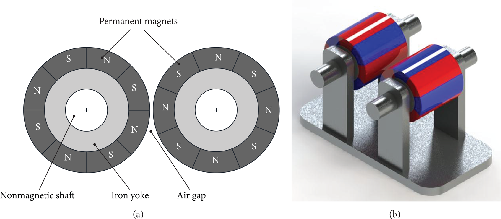
An external-meshed magnetic gear train with a gear ratio of 1: 1.
3. Finite-Element Analysis and Discussion
The FEA is a numerical technique and a reliable tool for dealing with the design and analysis of engineering products before actually manufacturing prototypes. When the geometric discretization is fine enough, it provides accurate estimations even for complicated geometrical structures. Because it is essential to predict the transmitted torque when designing a magnetic gear train, the FEA is indispensable to the transmitted torque analysis of magnetic gear mechanisms. A commercial 2D FEA package, Ansoft/Maxwell, was employed to assist in predicting the magnetostatic field and transmitted torque of the external-meshed magnetic gear train shown in Figure 1. Table 1 lists the material and geometrical specifications of the external-meshed magnetic gear train, while geometrical variables are defined in the cross-section of the magnetic gear train as illustrated in Figure 2. Figure 3 presents the transmitted torque against the rotational angle when the driven magnetic gear is kept stationary and the driving magnetic gear is rotating. The transmitted torque is a periodic torque that varies with respect to the rotational angle of the driving magnetic gear. The period of the transmitted torque waveform is 360°/p, where p is the number of pole pairs. As shown in Figure 3, the period of the transmitted torque is 360°/4 = 90° for a magnetic gear with four pole pairs. Maximum transmitted torque occurs when the rotational angle is half that of the magnet arc, that is, 22.5°. Once the driving torque exceeds the maximum transmitted torque, slipping occurs. It is a unique function of overload protection that mechanical gears are not provided with. The speed reduction ratio of this external-meshed magnetic gear train is – 4/4 = – 1. When the driven magnetic gear is propelled by the driving magnetic gear, a transmitted torque transient waveform is obtained, as shown in Figure 4. It is noted that an inherent torque ripple occurs in such an external-meshed magnetic gear train. The period of the ripple torque is 360°/(2p) = 360°/(2*4) = 45°. The torque ripple, which is defined by the difference between the maximum and minimum transmitted torque divided by the average transmitted torque, is (5.44 – 4.95)/5.20 = 9.42%. Because torque ripple may induce serious vibration and prevent a smooth rotation, suppression of torque ripple for magnetic gear trains is a major concern for engineering designers, especially in high-precision speed and position control applications. In what follows, the effects of the number of pole pairs, direction of magnetization, length of the air gap, thickness of iron yoke, and magnet shape of the maximum transmitted torque and torque ripple are discussed by applying FEA. For comparison purposes, the volume of the permanent magnet of each magnetic gear train is designed to be identical.
Material and geometrical specifications of the external-meshed magnetic gear train shown in Figure 1.


Geometrical variables of the external-meshed magnetic gear train.

Transmitted torque waveform when the driven magnetic gear is kept stationary and the driving magnetic gear rotates.

Transmitted torque transient waveform.
3.1. Number of Pole Pairs
Figure 5 shows the number of pole pairs versus the torque ripple of an external-meshed magnetic gear train with a gear ratio of 1: 1. The figure indicates that the torque ripple effectively decreases as the number of pole pairs increases. The period of the ripple torque is 360°/(2p); it decreases as the number of pole pairs increases. The frequency increases in accordance with the decrease of the period due to the reciprocal relationship and decreases the amplitude of the ripple torque so as to reduce the torque ripple. In addition, the maximum transmitted torque also decreases when the number of pole pairs increases, as shown in Figure 6.

Relationships between the torque ripple and the number of pole pairs.
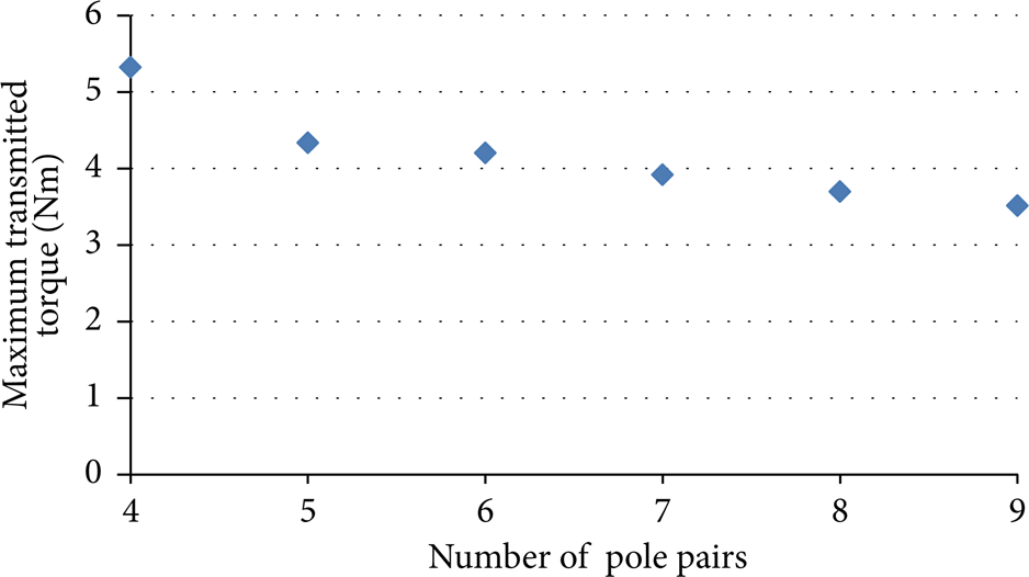
Relationships between the maximum transmitted torque and the number of pole pairs.
3.2. Direction of Magnetization
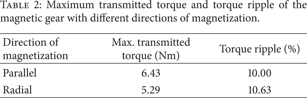
Sector-shaped permanent magnets are usually magnetized in radial or parallel directions. Table 2 compares the maximum transmitted torque and the torque ripple of an external-meshed magnetic gear train with the different directions of magnetization. As presented in Figure 7, a magnetic gear train equipped with permanent magnets and with parallel magnetization generates higher transmitted torque and lower torque ripple than those with radial magnetization.
Maximum transmitted torque and torque ripple of the magnetic gear with different directions of magnetization.
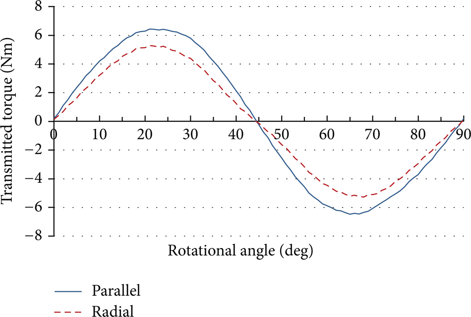
Comparison of transmitted torque for permanent magnets with radial and parallel magnetizations.
3.3. Length of the Air Gap
The air gap is the area that stores magnetic energy for magnetic gear trains. Figures 8 and 9 indicate the maximum transmitted torque and torque ripple plotted against the length of the air gap, respectively. Because the magnetic force decreases in accordance with the increase of the distance, both the maximum transmitted torque and the torque ripple decrease as the length of the air gap for the external-meshed magnetic gear train increases.

Relationships between the maximum transmitted torque and the length of the air gap.
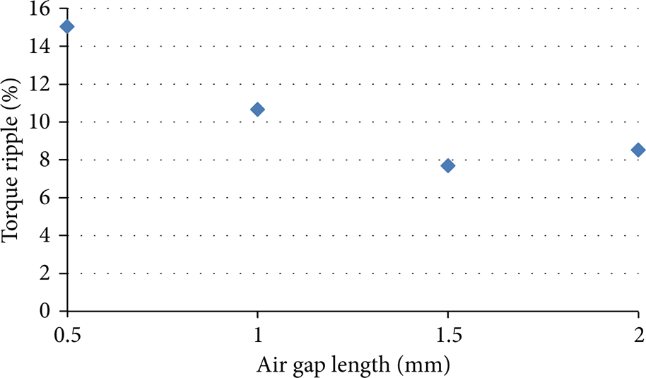
Relationships between torque ripple and the length of the air gap.
3.4. Thickness of the Iron Yoke
The function of the iron yoke is to support permanent magnets and provide the flux returning paths. Figures 10 and 11 depict the maximum transmitted torque and the torque ripple plotted against the thickness of the iron yoke. We found that the absence of the iron yoke, that is, the thickness of the iron yoke is zero, leads to serious flux leakage and results in poorly transmitted torque and high torque ripple. When the length of the iron yoke is less than 1 mm, magnetic saturation occurs within the iron yoke. Figures 12(a) and 12(b), respectively, show the magnetic flux density distribution of magnetic gear trains with lengths of iron yoke equal to 0.5 mm and 1 mm. The maximum magnetic flux densities within the iron yoke for these two cases are larger than 3 T, which exceeds the saturated magnetic flux density of 1.39 T of the magnetic sheets. It substantially reduces the maximum transmitted torque and brings about undesirable high torque ripple. When the length of the iron yoke is larger than 5 mm, the external-meshed magnetic gear train generates a higher transmitted torque and lower torque ripple than those with magnetic saturation. Therefore, magnetic saturation should be avoided when designing a magnetic gear mechanism.

Relationships between the maximum transmitted torque and the thickness of the iron yoke.
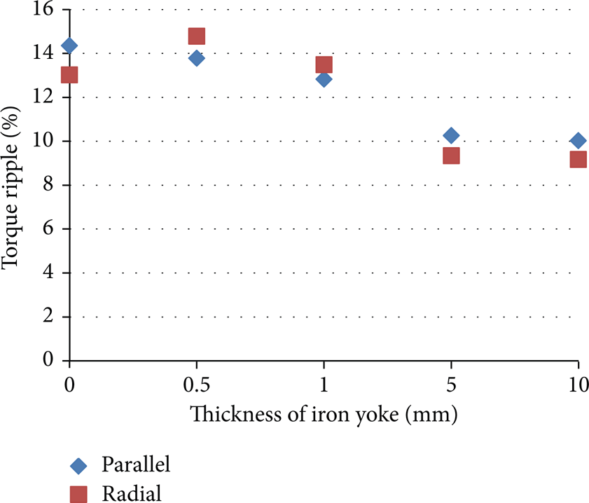
Relationships between torque ripple and the thickness of the iron yoke.
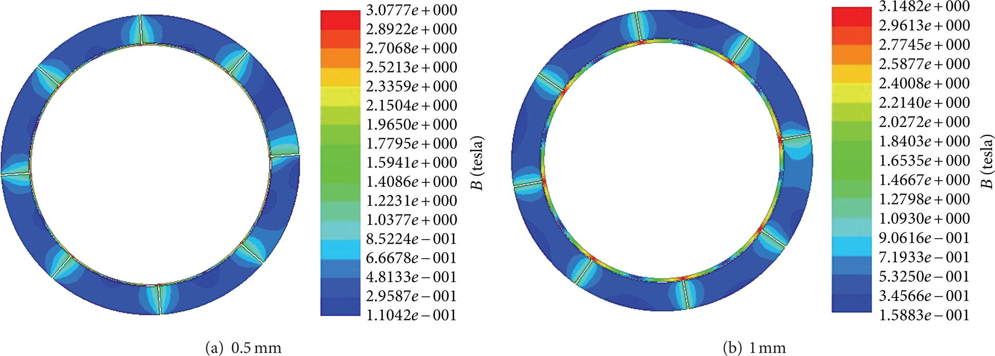
Magnetic saturation occurring in the iron yoke when the lengths of the air gap are 0.5 mm and 1 mm.
3.5. Shape of the Permanent Magnet
Magnetic gears equipped with sector-shaped and rectangular permanent magnets are also discussed. From the geometry point of view, rectangular magnets have the advantages of standard product specifications, low manufacturing cost, and easy magnetization. However, two meshed magnetic gears with rectangular magnets may create interference when the length of the air gap is insufficient. Figure 13 presents the maximum transmitted torque versus the number of pole pairs for magnetic gears with sector-shaped and rectangular permanent magnets. The length of air gap is set as 3.5 mm for the magnetic gear train with rectangular magnets in order to avoid interference. In order to make a quantitative comparison, the length of air gap for the magnetic gear train with sector-shaped magnets was set to be identical with the rectangular magnets. This demonstrates that the magnetic gear train equipped with sector-shaped magnets performs better than one with rectangular magnets for the maximum transmitted torque. However, the magnetic gear train equipped with rectangular magnets possesses lower torque ripple than the one with sector-shaped magnets, as presented in Figure 14.

Relationships between the maximum transmitted torque and the number of pole pairs for magnetic gear trains with sector-shaped and rectangular magnets when the length of the air gap is 3.5 mm.
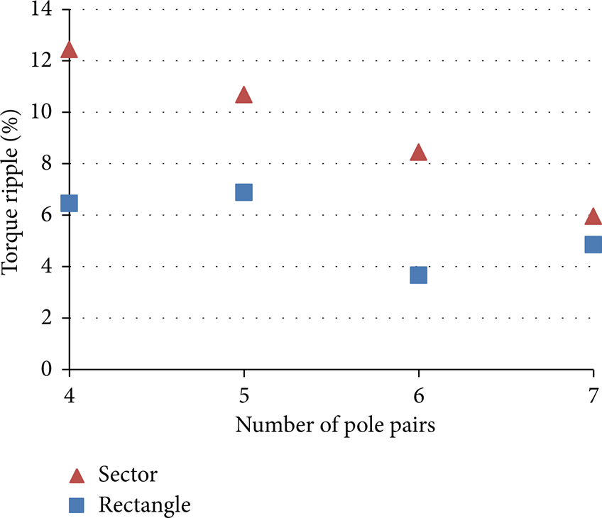
Relationships between the torque ripple and the number of pole pairs for magnetic gear trains with sector-shaped and rectangular magnets when the length of the air gap is 3.5 mm.
4. Results
Based on the above discussions, the effective strategy for designing an external-meshed magnetic gear train with high transmitted torque is to decrease the number of pole pairs as well as the length of the air gap for the sector-shaped magnets, to select permanent magnets with sector-shaped and parallel magnetization, and to prevent magnetic saturation within the iron yoke. However, to construct an external-meshed magnetic gear train with low torque ripple, it is necessary to increase the number of pole pairs as well as the length of the air gap of the sector-shaped magnets, to select permanent magnets with a rectangular shape, and to prevent magnetic saturation within the iron yoke. Because transmitted torque is achieved by the direct interaction of closely arrayed permanent magnets, only these permanent magnets contribute to generating the transmitted torque for the proposed magnetic gear train. Such an external-meshed configuration results in low torque density compared to coaxial type magnetic gear mechanisms.
5. Conclusions
This paper discusses the transmitted torque characteristics of an external-meshed magnetic gear train by using FEA. The results show that the torque ripple of the magnetic gear train can be minimized by increasing the number of pole pairs and the length of the air gap for sector-shaped magnets, properly selecting permanent magnets with a rectangular shape, and preventing magnetic saturation within the iron yoke. Upcoming work on this topic involves investigating the effects of compound magnetic gears and the gear ratios of external-meshed magnetic gear trains on the maximum transmitted torque and torque ripple.
Conflict of Interests
The authors declare that there is no conflict of interests regarding the publication of this paper.
Footnotes
Acknowledgments
The authors thank the National Science Council (Taiwan) for supporting this research under Grant NSC 102-2221-E-224-016-MY2. They also thank the National Yunlin University of Science and Technology for supporting research apparatuses.