
Abstract
The interflow plays important roles in centrifugal pump design. In order to study the effect of rotation and z-axis on internal flow, two-dimensional particle image velocimetry (PIV) measurements have been performed to measure the steady velocity field on three planes in all impeller passages of a low specific-speed centrifugal pump. The results show that the relative velocity flows in blade passages are obviously different in terms of the positions of the blade relative to the tongue. The interaction between the impeller and tongue changes the occurrence and development of low velocity region with time. From shroud to hub, the relative velocity gradually increases, and the minimum value moves toward the suction surface. On the midplane, the magnitude increases with increased flow rate from pressure surface to suction surface, while at the shroud and hub, the measured velocity first increases with decreased flow rate from the blade pressure surface to nearly ζ = 0.5 to 0.6.
1. Introduction
Centrifugal pumps play important roles in a wide range of industrial applications. The internal flow that develops in pump predetermined by the geometry negatively affects the machine's performance in terms of efficiency, vibration, and noise, especially at off-design conditions [1]. It is of great significance to improve internal flow in centrifugal pump, and experimental study is the most basic and credible research method.
In the past, a variety of measurement techniques, particularly pressure probes and hot-wire anemometry, have been applied in strive for accurate quantitative flow descriptions. These methods have provided much fundamental knowledge of flow phenomena occurring in centrifugal pumps. However, most of them are intrusive techniques, with some disadvantages such as the space limitation, probe interference, equipment precision, and so forth. The particle image velocimetry (PIV) technique is a powerful method which offers a more detailed knowledge of local features of the impeller flow [2–7]. At present, PIV measurement of internal flow in centrifugal pumps focuses on the flow in only one impeller passage rather than all impeller passages, and less attention is paid to the rotation and z-axis to the influence of internal flow.
Sinha and Katz [8] and Sinha et al. [9] used PIV to study rotor-stator interactions between a centrifugal pump impeller and a vaned diffuser, addressing both flow structure and turbulence modeling issues. Stickland et al. [10] measured the flow patterns between the blades of a centrifugal pump impeller with PIV, obtained velocity contours and vector maps of the relative flow field. Westra et al. [11] observed secondary flows from the velocity measurements and found that these flows result in the formation of low velocity regions near the intersection of blade suction side and shroud. The extent of this jet-wake structure decreases with increasing flow rate.
The main motive of this paper is to measure steady flow fields in whole impeller flow passages on different z planes. And, to justify the accuracy and resolution of the measuring results, the sampling number is investigated and the corresponding measuring error of average velocity is computed.
2. Geometry of the Test Model
The model pump constructed for PIV measurements consists of an impeller, a volute, and a suction chamber. Owing to the limit of land and to facilitate arrangement of optical system and CCD camera, the central side-inlet for pump is adopted. The impeller is shrouded with six strongly backward curved blades with an exit angle of 40° relative to the tangential direction. The volute is designed using equivalent velocity moment method, featured by rectangular cross-sections and logarithmic spiral profile. In order to reduce scattering in PIV measurements, the volute is designed as square shape. Both the impeller and volute are made of acrylic glass for good optical access. Acrylic glass is homogeneous with no bubbles or impurities. All surfaces of acrylic glass are polished, and its roughness is up to Ra3.2. Besides, for reducing background noise, nontesting surfaces of the impeller and volute near the suction chamber are set to black before assembly. The geometric data and design operating condition of the pump are summarized in Table 1. The meridian section of the pump is shown in Figure 1, where z means the distance from the measuring plane to the hub. The structures of the model pump, such as impeller and volute, are shown in Figure 2.
Pump geometry and design operating condition.


Meridian section of the pump.
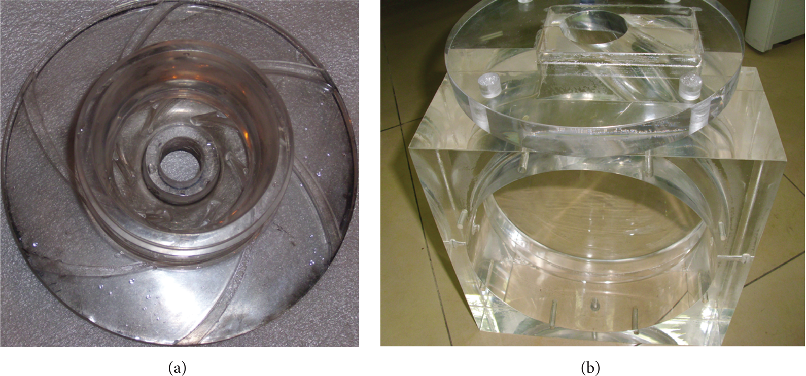
Structures of the model pump: (a) impeller; (b) volute.
3. Experimental Setups
The pump is driven by a three-phase asynchronous motor. A water tank feeds the water into the pump and also recollects the water out of the pump. An electromagnetic flow meter measures the volume flow with the uncertainty less than ±0.5%, which can be adjusted by a hand valve installed on the pipe behind the pump. Pressure probes in the suction pipe and downstream of the impeller measure the pressure before the pump and the pressure difference over the impeller. The uncertainty was within ±0.14%. The shaft torque and rotational speed were measured by a torque and speed sensor with errors under ±1.08%. The measurement accuracy of pump efficiency was quantified as ±1.2%.
3.1. PIV Flow Measuring Technique
A 2D PIV nonintrusive measurement system of TSI Inc. in 2009 was utilized to acquire velocity distributions, as shown in Figure 3.
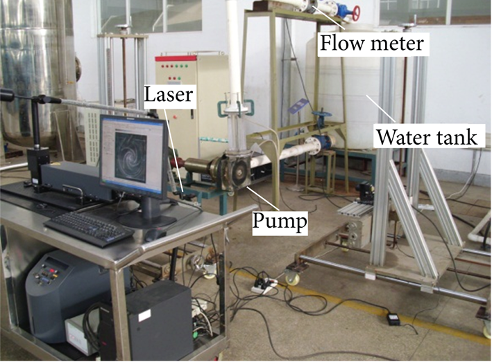
2D PIV system.
The light source is a double-pulsed 532 nm Nd:YAG laser operated at 30 Hz with a pulse duration from 3 ns to 5 ns and laser beam intensities adjusted to 200 mJ per pulse. An articulated light-guiding arm directs the pulsing laser beams to the test rig where cylindrical optics produced a light sheet with a thickness of approximately 3.5 mm. Water is seeded with Al2O3 particles to produce homogeneous and dense seeding distribution that ensures a minimum of 3 to 20 particles per interrogation area. A CCD camera with a resolution of 2k × 2k pixels and mounted perpendicular to the laser sheet is used for particle image capture. This camera is equipped with an optical high-pass filter that transmits only fluorescent light and thus prevents scattered green light from reaching the CCD sensor. Image acquisition is synchronized with respect to impeller rotation using a once-per-revolution pulse obtained from an encoder installed on the pump shaft. During the PIV test, the stepless speed regulation by the inverter control cabin causes the electric signals to seriously disturb the external trigger pulse signals. Therefore, an external synchronous trigger system utilizing optical fiber technology is adopted. By allowing the trigger signal to pass an adjustable delay circuit, this procedure allows a large number of instantaneous samples to be obtained at fixed circumferential positions of the pump and calculate ensemble averages. Yang et al. [12] pointed out that sampling number of PIV measurement affects the average velocity, whose value is almost constant when the sampling number is >100. Thus, the number of image sets obtained at the same location in the pump is 100 in this paper. Figure 4 shows the velocity variation at P1, P2, P3, and P4 with a sample number at the impeller outlet when φ = 0° under the design flow rate Q d . The velocity at each measuring point changes with time at a turbulence state. The disturbance of blades is regarded as periodic change. The standard uncertainties of average velocity for P1, P2, P3, and P4 are 2.60%, 2.59%, 2.57%, and 2.42%, respectively.

Velocity variation at P1, P2, P3, and P4 with sample number.
The PIV images are processed into vector maps using the cross-correlation method. The method allows displacements from an image pair to be determined in combination with a median filter to reduce the number of spurious displacement vectors. Image processing is performed offline on a 64-bit PC running an in-house FFT-based software platform Insight 3 G.
The calibration target cannot be placed into the pump because of the closed flow field. Thus, a previously reported equivalent calibration method [13] is used, as shown in Figure 5. The target is placed at the center of the laser light sheet using traverse micrometer adjustment achieved by viewing the reflection off the mirror in the target frame. When the target is at the center of the light sheet, the reflected light is maximized. When looking at the alignment mirror slit, the light sheet has even light on either side of the slit.
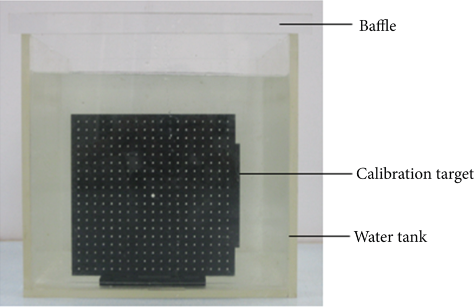
2D calibration.
3.2. Measuring Region
PIV measurements are performed inside the impeller passages on three planes, that is, at z/b2 = 0.125 (called hub plane), z/b2 = 0.875 (shroud plane), and z/b2 = 0.5 (midplane), as illustrated in Figure 1. Six different phase conditions at six flow rates are measured, including φ = 0°, 10°, 20°, 30°, 40°, and 50° with a phase interval of 10°. Figure 6 shows the phase position of φ = 0°, at which placing the camera is found to be advantageous.

Sketch of measurement region.
4. Results and Discussion
4.1. Effect of Rotation on Relative Velocity
Given that the camera frame is fixed in space, the readily obtained velocity field is the absolute velocity

Relative velocity contours at midplane for Q d .
Figure 8 shows the change of mean dimensionless relative velocity (w/u) along the circular arc with r/R2 = 0.90 from pressure surface (PS) to suction surface (SS) at the shroud plane in blade passage A. Here, w is the magnitude of the relative velocity vector

w/u at shroud in balde passage A.
4.2. Effect of z-Axis on Relative Velocity
Figure 9 shows the change of w/u on three planes at φ = 0° for three considered flow rates. The velocity at r/R 2 = 0.90 increases from shroud to hub, and the minimum value moves toward the suction surface from the pressure surface. On the midplane, the mean dimensionless relative velocity increases with increased flow rate from pressure surface to suction surface. A different pattern is observed at the shroud and hub, in which the measured mean dimensionless relative velocity initially increases with decreased flow rate from the blade pressure surface to nearly ζ = 0.5 to 0.6.

w/u on three planes in balde passage A at φ = 0°.
5. Conclusions
Two-dimensional PIV experiments were carried out in a centrifugal pump on the three planes. The effects of some factors including pump rotation and z-axis, on internal flow, were investigated. The following conclusions were then drawn.
As passage A rotates away from the tongue, a local region with small velocities is observed near the blade suction surface, and this region develops into vortex. However, when the blade rotates ≥30° from the tongue, the low velocity region weakens. Correspondingly, the vortex gradually weakens and ultimately disappears. The flow in blade passage A smoothens. All these results indicate that the interaction between the impeller and tongue changes the occurrence and development of vortices with time. Moreover, the frequent change in regions and strength of vortices inevitably leads to an unsteady flow.
Intersections of w/u lines under six flow conditions from φ = 0° to 30° are observed at the shroud. The relative velocity first increases with decreased flow rate and then increases with increased flow rate. When the impeller rotates to φ = 40° and 50°, the velocity first increases from the blade pressure surface to the suction surface, reaches the maximum, and then decreases close to the blade suction side. Thus, a visible jet-wake effect pattern forms at the shroud.
Velocity increases from the shroud to hub, and the minimum value moves toward the suction surface from pressure surface. On the midplane, the magnitude increases with increased flow rate from pressure surface to suction surface. A different pattern is observed at the shroud and hub; that is, the measured velocity first increases with decreased flow rate from the blade pressure surface to nearly ζ = 0.5 to 0.6.
Conflict of Interests
All author declare no conflict of interests. The support of the National Natural Science Foundation of China (nos. 51309119, 51179075, and 51109095), a project funded by the Priority Academic Program Development of Jiangsu Higher Education Institutions, and the Advanced Talent Foundation of Jiangsu University (12JDG082) have no conflict of interest.
Footnotes
Acknowledgments
This work was supported by National Natural Science Foundation of China (nos. 51309119, 51179075, and 51109095), a project funded by the Priority Academic Program Development of Jiangsu Higher Education Institutions, and the Advanced Talent Foundation of Jiangsu University (12JDG082).