
Abstract
Fuel pump is a crucial component in aircraft engine ignition system. For the hi-speed axial fuel pumps, rotating stall triggers vortex and affects the operation stability and security. Sweep blade is widely used to solve the stability problems in aerodynamics field. Investigation on the hydrodynamics was conducted in this study. Based on the typical straight blade pump, positive and negative sweep blade pumps were modeled. With the large eddy simulation method, CFD simulations were conducted to calculate and analyze the flow characteristics in the pump models. To verify the simulation, experiments were also launched on the hydraulic test rig. Results show that the vortex occurs at the suction surface of blade and gathers near the blade tip region. Positive sweep blade is effective to reduce the hydraulic losses by driving the stalled fluid into the mid-part of blade. By applying the positive sweep blade on the axial fuel pump, the instability operating region will be diminished. Adopting sweep blade provides an effective means for stability and security of axial fuel pumps.
1. Introduction
Hi-speed axial fuel pump is a crucial component of aircraft engine ignition system. To evaluate the hydrodynamic performance of hi-speed axial fuel pump, efficiency and stability are the most important consideration factors. Under off-design conditions, rotating stall happens at blade leading edge and triggers vortex and secondary flow in the impeller. Efficiency and stability will be influenced by these undesirable flow structures. The sweep blade which is designed by stacking airfoil profiles along a dihedral line has been proved successful in improving the flow stability in recent studies. Compared with the conventional radial-straight-line stacking blade, dihedral-line stacking (sweep) blade can reduce hydraulic losses near tip clearance by controlling secondary flows [1].
Aerodynamics of sweep blade had been investigated and analyzed by many researchers [2–5]. Results by Li et al. [2], Vad [4], and McNulty et al. [5] show that sweep blade can improve the aerodynamics performance of fans and compressors, including increasing total-pressure peak value, enhancing efficiency, and widening no-stall range. By both CFD simulations and experiments, Gallimore et al. [1, 3] investigated sweep blade in hi-speed axial compressors. In their investigations, sweep blade could perform well or badly by stacking airfoil profiles along different dihedral directions. That means that positive and negative dihedral stacking (sweep) will generate different pressure gradient fields. It will change the radial pressure gradient and induce a velocity field which has a significant effect on tip clearance vortex generation and blade loading distributions [6, 7]. For axial pumps, especially under a low-discharge condition, stall and blocking usually occur near endwall regions. Experiments by using calibrated five-hole pressure probes [8] or PIV and LDV technique [9] were carried out to study the backflow, vortex, and flow uniformity under different conditions. CFD simulations also investigated these flow characteristics and their impacts on hydrodynamic performance of pump [10]. Results show that these undesirable flow structures would cause operating instability and vibration.
Even though the investigations and applications of sweep had widely launched on fans and compressors [2, 11], the hydrodynamics of sweep blade especially in axial pumps have hardly any investigation information. Based on the successful applications on compressor in widening the stable operating range, this paper investigated the hydrodynamics of sweep blade in high-speed axial fuel pump. The performances of positive-dihedral, negative-dihedral, and straight-lined stacking blades will be investigated with both numerical and experimental methods. This investigation would find out how to enhance the operating stability and efficiency of hi-speed axial pump and provide valuable references in engineering application.
2. Modeling
2.1. Definition of Sweep
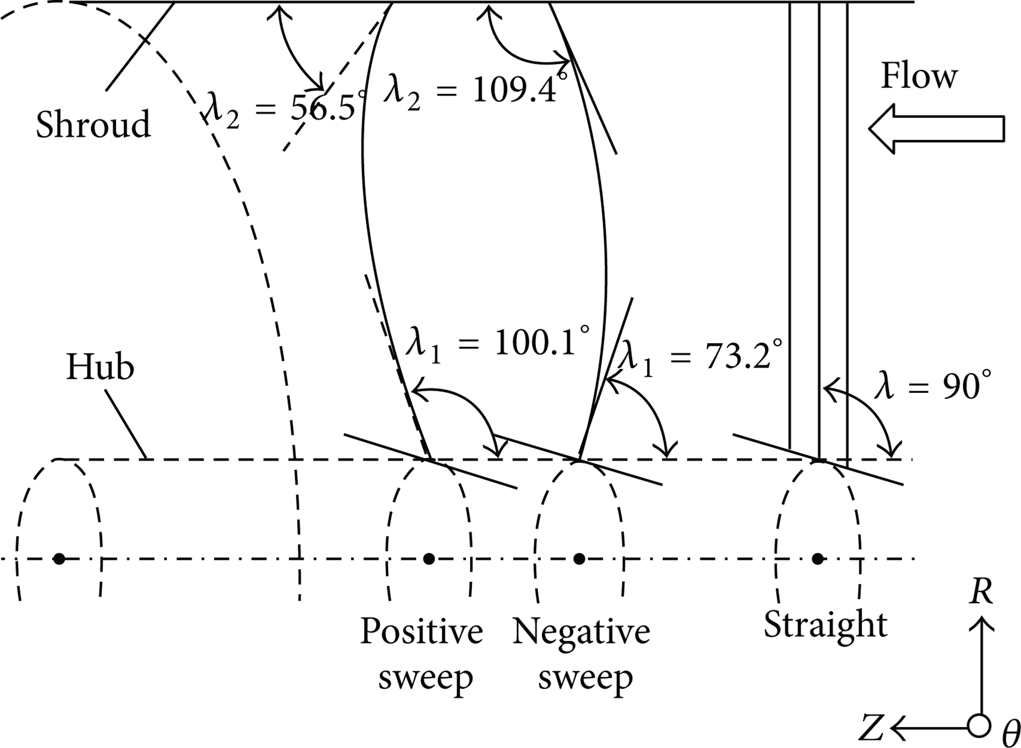
For axial pumps, blade consists of sections of designed foil profiles. The stacking line is defined as passing through the center of gravity of each foil profile. In conventional designs, foil profiles are stacked along a radial straight line. As shown in Figure 1, based on the straight stacking line in the meridional plane, dihedral stacking line is created by bending it along z-axis with angle of λ. Then, sweep blade is modeled with the dihedral stacking. It has been mentioned above that positive and negative sweep would have diverse effects on hydrodynamic performance of axial pump. As shown in Figure 2, in axial pump, positive sweep is defined as bending the stacking line following the flow direction. Otherwise, bending in the opposite direction is known as the negative sweep.
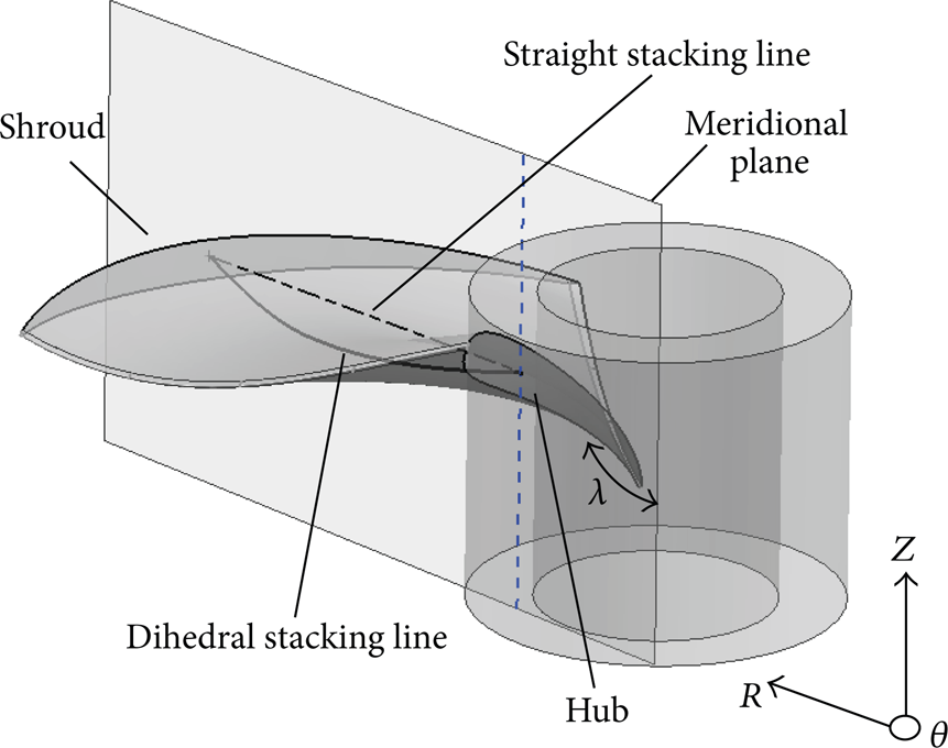
Definition of dihedral stacking line and sweep impeller blade.

Definition of positive and negative sweep.
2.2. Modeling of Comparison Samples
In order to investigate the hydrodynamics performance of straight, positive, and negative sweep blade in axial pump, three impeller samples were modeled and are shown in Figure 2. The straight blade impeller is the original model which was designed in a conventional way. The impeller consists of 4 blades with the outside diameter of 70 mm. The rotating speed of impeller is 8000 r/min and the rated flow rate is 10.75 kg/s. Based on the original model, the positive sweep blade was designed by bending the stacking line and keeping other geometry parameters consistent. The stacking line was modified on the basis of the “boundary layer velocity distribution law” [12]. With this velocity distribution low, the tangential relative velocity Wθ and axial absolute velocity C Z were corrected. Flow angles were changed with the corrected velocity components so that the positive and negative stacking line was built. Figure 3 shows the modified stacking line samples of the three impellers.
Straight, positive, and negative stacking lines of the 3 impeller samples.
3. Numerical Simulations
3.1. Large Eddy Model
Considering the fully developed flow with high Reynolds numbers in the axial fuel pump and possible secondary flow and tip clearance vortex, large eddy simulation (LES) [13] was used as the suitable solution approach in the CFD simulations. With the filtering operator, the quantities in turbulence flow could be decomposed into large and small parts. The filtering operator is defined as follows [14]:

where ϕ(x
i
) is the processed quantity and

where

where
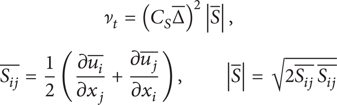
and C
S
is the Smagorinsky constant with the value of 1.0 in this study and
3.2. Preprocessing
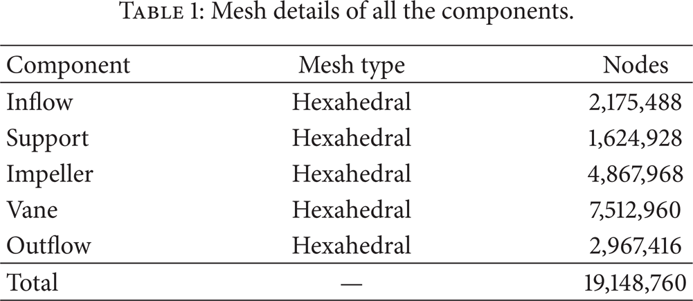
Before starting the CFD simulations, preprocessing is conducted with meshing the domain and setting simulation parameters. The flow domain consists of 5 components including inflow, support, impeller, vane, and outflow and is shown in Figure 4. The outside diameter of impeller is 65 mm. There are 4 blades in the support, 4 blades in the impeller, and 7 blades in the vane. The lengths of inflow and outflow are both 150 mm. These domains were discretized with all hexahedral elements by using the commercial software ICEMCFD. The completely solved mode is used at near wall region with the first mesh layer of 10−2 mm. To solve the case accurately, mesh size was considered concretely with an independence study. The maximum core-region mesh scales of about 3 mm, 1 mm, 0.35 mm, 0.1 mm, 0.035 mm, and 0.01 mm were studied under the design flow rate condition. Efficiency was chosen as the criterion and varied less than 1% when the scale decreased to 0.035 mm. Meanwhile, the maximum y+ at all the walls was 5.325. It means that the mesh could almost be distributed in the viscous sublayer. Hence, the mesh scheme was confirmed to use in the study with the maximum scale of about 0.035 mm. The total number of nodes of the whole flow domain is about 19′148′760. The mesh details are shown in Table 1 and the partial enlarged view of near-wall region at impeller blade is shown in Figure 5.
Mesh details of all the components.

Components of the whole flow domain of axial pump.

The near wall mesh at the intersection between impeller blade and shroud.
With the completed mesh, large eddy simulation was conducted by using the commercial software ANSYS CFX. In the simulations, the compressibility, heat transfer, and phase change were not taken into account. Settings before simulation are described as follows and consist of 2 parts. At first, the steady state simulation with SST k-ω turbulence model [15] was conducted to provide the initial value for LES. In boundary conditions, inflow inlet was set to be the mass flow inlet of 11 kg/s as the design value and varied from 3 to 12 kg/s. Outflow outlet was set as the pressure outlet of 0 Pa and all the walls were set to be no-slip wall boundary. The reference pressure was set to 1 Atm. The multiple reference frame (MRF) model [16] was used in the simulation. The impeller domain was set as rotating domain with a rotating speed of 8000 r/min and other domains were stationary. The material of fluid is aviation fuel whose density is 780 kg/m3 and dynamic viscosity is 1.5 × 10⁻³ kg/(m·s). The steady state simulation was completed with convergence criteria of 10−5 and 500 iterations at most in physical time scale of 5.968 × 10⁻⁴ s. Then, based on the steady results and keeping the boundary conditions, environments, and material consistent, LES (transient) was conducted in 3 impeller revolutions (about 0.0075 s) with 360 time steps per revolution. The maximum coefficient loops were set as 10 with convergence criteria of 10−5.
3.3. Flow Analysis
3.3.1. External Characteristics
After the CFD simulations, results were obtained. The variation of differential pressure between domain inlet and outlet and hydraulic efficiency with flow rate is shown in Figure 6. The differential pressure (ΔP) represents the energy capability of pumps. As shown in Figure 6, with flow rate decreasing, ΔP rises in general but may vary up and down in some local regions. In the typical straight blade pump, ΔP drops at the volume flow rate Qv of 9.5 L/s and rises again at Qv of 8.5 L/s. This variation generates an unstable region which is harmful for operation. By contrast, the Qv – ΔP curve of positive sweep blade pump varied smoothly with no obvious drop around Qv of 9 L/s. For the negative sweep blade pump, even though, there is no tremendous change in the Qv – ΔP curve but the ΔP is much lower than positive sweep and straight blade pump from Qv 8 L/s to 10 L/s. From the hydraulic efficiency curves, it is obvious that the efficiency of negative sweep pump is lower than that of positive sweep and straight pumps. What is important is that the efficiency increased slightly after positive sweep modification.
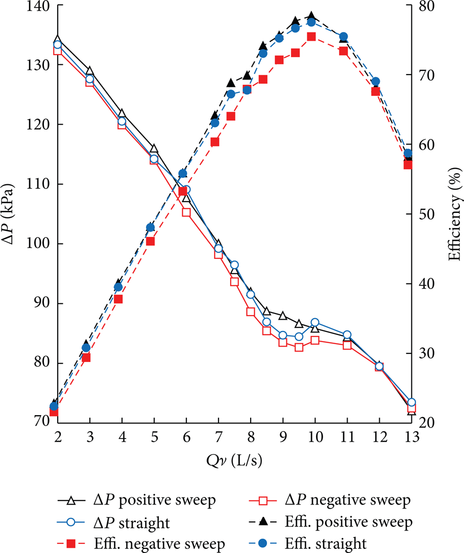
The variation of differential pressure and hydraulic efficiency with flow rate in the three pump models.
3.3.2. Separation Vortex at Blade Tip
To investigate why the energy character (ΔP) dropped in straight and negative sweep blade pumps, streamlines near shroud are shown in Figure 7(a). Under the condition of Qv = 9 L/s, vortex occurred near leading edge in the straight blade pump and occurred near both leading edge and trailing edge in the negative sweep pump. Streamlines in meridional view at leading edge position are also drawn in Figure 7(b). It is shown that the vortex gathered at the corner between blade suction surface and impeller shroud in negative sweep and straight pumps. As shown in Figure 7, in the positive sweep pump, the flow pattern is smooth without undesirable flow structure.
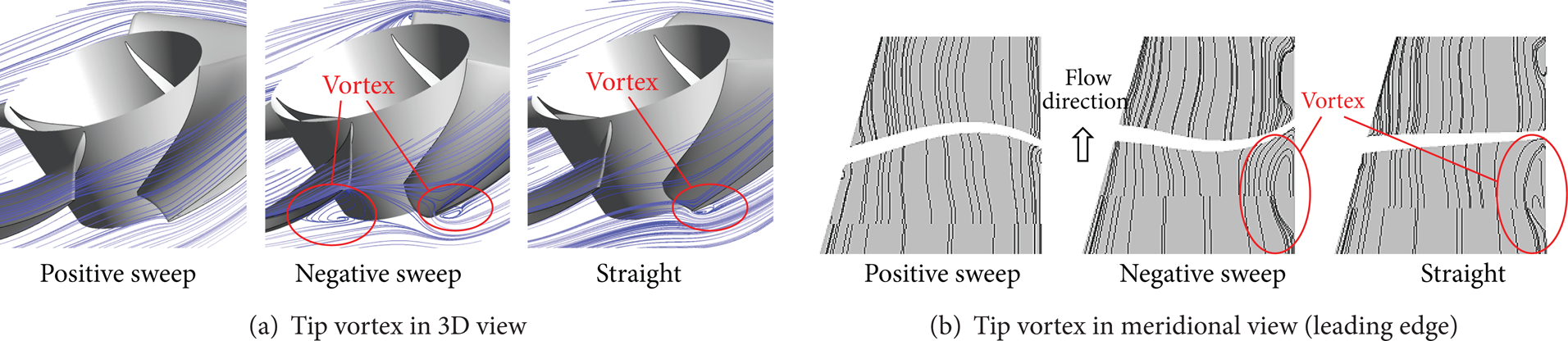
Streamlines near impeller blade under Qv = 9 L/s condition.
For the typical straight blade, with flow rate decreasing, stall happened at the blade leading edge and generated vortex in suction surface. The vortex moved to shroud due to the rotating centrifugal force. Because of the low pressure in the suction surface, vortex gathered in the tip region and blocked the flow passage. Hydraulic losses became serious so that the energy capability of pump dropped.
3.3.3. Efficacy by Sweep Modifications
After sweep modifications on the blades, flow regime changed in the pump impeller. As shown in Figure 8, it plays big differences on the flow patterns among the positive sweep, negative sweep, and straight blades under Qv = 9 L/s condition. In Figure 8, six reference positions near leading edge are marked for comparison. Positions 1, 2, and 3 are near shroud and positions 4, 5, and 6 are near hub. On the suction surface of straight blade, fluid flow toward the shroud as position 2 shows. At the same time, fluid separates away from the hub as shown in position 5. In the positive sweep pump, as shown in position 1, fluid turns to flow along the shroud direction. It is effective to diminish the gathering tip vortex. In the negative sweep pump, as shown in position 6, fluid flows along the hub.
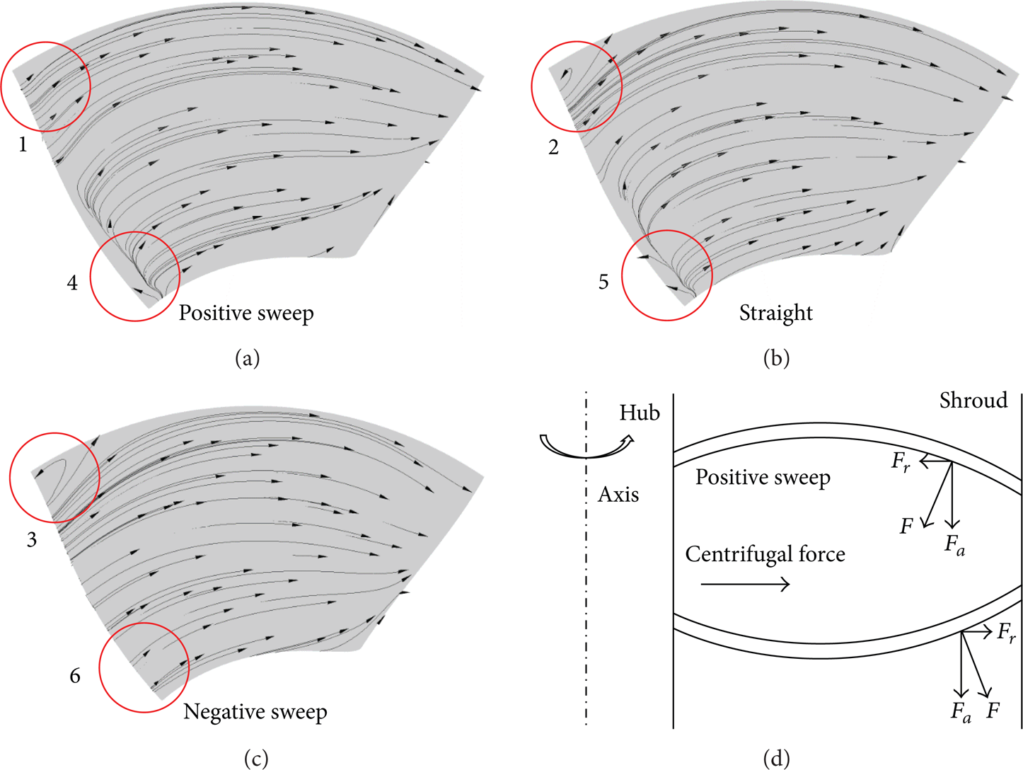
Flow patterns on the positive sweep, negative sweep, and straight blades under Qv = 9 L/s condition and the schematic plot of F r force produced by sweep blade.
The radial equilibrium equation in meridional plane is shown below:
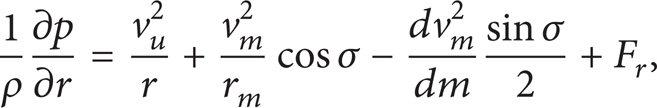
where ρ is the density of fluid, p is the pressure, r is the radius, v u is the circumferential velocity, v m is the meridional velocity, σ is angle between meridional velocity v m and axial direction, and m denotes the mass.
In detail, the left side of this equation is the variation of pressure along radial direction and is affected by the four items on the right side. The first item on the right side represents the centrifugal force formed by the impeller rotating. The second item is the radial component of the centrifugal force formed by meridional curvature movement. The third item is the radial component of acceleration force in meridional movement. The last item, F r , is the radial component of the force given by the impeller blade in meridional movement. As for axial pump, the effects of the 2nd and 3rd items are very small. And, for straight blade pump, the 4th item is also very small. The centrifugal force by impeller rotating is obvious and always from hub to shroud. Hence, vortex moved toward shroud and gathered at blade suction surface as mentioned above.
Compared with straight blade, sweep blade will produce an extra F r force (the 4th item) which is as big as rotating centrifugal force (the 1st item). If the efficacy of F r is bigger than the sum of item 1∼3, the negative radial pressure gradient may occur. The F r forces produced by sweep blades are also shown in Figure 8. In the positive sweep blade pump, the direction of F r is opposite to the rotating centrifugal force. So, driven by the F r force, vortex did not gather in the tip region but moved into the middle part of blade. In the negative sweep blade pump, F r and centrifugal force are in the same direction. Hence, the flow condition gets worse and the hydraulic losses become more serious.
3.3.4. Trailing Edge Flow Uniformity
Figure 9 shows the comparison on trailing edge flow uniformity among the positive sweep, negative sweep, and straight blade pumps. The horizontal axis is the blade span which is 0 at hub and 1 at shroud. The vertical axis is the velocity coefficient W/U where W is the relative velocity and U is the linear velocity at blade tip. In the positive sweep pump, the value of W/U became more uniform than that in the negative sweep and straight pumps. Affected by the positive sweep geometry, tip vortex moved into the mid-blade region and was pushed out of the impeller. With the improvement of flow condition, the unstable region in the Qv – ΔP curve is eliminated.

The velocity coefficient W/U distributions along blade span at trailing edge.
4. Experiment Verifications
To verify the CFD simulation results, experiments were conducted on the test rig shown in Figure 10. As shown in Figure 10, straight and positive sweep blade impellers were manufactured. Standard pressure manometers were used for the measurements on the differential pressure, and an electromagnetic flow meter was used to acquire the flow rate data. In the experiment, the uncertainties were found to be less than ± 1.5% for the differential pressure and less than 2.5% for the flow rate. The comparison on differential pressure value between CFD simulation and experiment is shown in Figure 11. With the experiment data, CFD simulation is proved to be accurate and credible. And it is also proved that the positive sweep blade is useful to eliminate or diminish the unstable Qv – ΔP region.

The models of straight and positive sweep impeller and the test facilities.

The comparison on differential pressure value between CFD simulation and experiment.
5. Conclusions
The hydrodynamics of sweep blade were investigated based on the hi-speed axial fuel pump. Comparisons between positive sweep, negative sweep, and straight blade pumps were conducted in CFD simulations. Experiment verification was also conducted on positive sweep and straight blade pumps by using the hydraulic test facilities. In this study, positive sweep is proved to be useful to improve the operating stability on axial fuel pump. The hydrodynamics are illustrated as follows.
For axial pump, with flow rate decreasing, stall happens at leading edge and turns into surface vortex on the blade. Driven by rotating centrifugal force, vortex moves from hub to shroud and gathers in the tip region. With vortex becoming large, flow passage is blocked that makes the hydraulic losses serious and reduces the power capability of pump.
Based on the theory of radial equilibrium equation, blade is modified from straight to sweep. The positive sweep blade will give an extra force to fluid which is opposite to the rotating centrifugal force. In the positive sweep pump, vortex forms within the mid-part of blade channel and flows out of the impeller and then it mixes with the main flow. With the application of positive sweep, the unstable Qv – ΔP region is diminished or even eliminated in the hi-speed axial fuel pump. It will provide a significant reference in engineering applications.
Footnotes
Acknowledgments
The authors would like to acknowledge the financial support offered by the Key Project of National Natural Science Foundation of China under Grant no. 51139007 and the Twelfth Five-Year National Science and Technology Support Project of China under Grant no. 2012BAD08B03.