
Abstract
An extremity rehabilitation program was proposed based on inertial measurement units (IMU) and virtual reality. A single IMU consists of a three-axis accelerometer, gyroscope, and geomagnetic sensors. One IMU is attached to the upper arm (master) and another to the forearm (slave). The IMUs are connected using a distributed sensor network implemented with interintegrated circuit communication. The motion-tracking algorithm running on a PC tracks the subject's hand based on the estimated IMU orientation and segment lengths through forward kinematics. The training contents, including various dynamic movements and static holds, were designed to evaluate the spatiotemporal aspects of the subject's functionality. The system was tested on a group of healthy subjects and a group with a simulated stiff elbow, allowing the evaluations to be quantitatively differentiated. The stiff elbow was simulated by taping the elbow to restrict the range of elbow motion. We expect the patients to be able to assess their own status without assistance from a therapist and select appropriate training methods to increase their rehabilitation effectiveness. Future studies will verify the availability and reliability of the upper extremity rehabilitation program for patients with a hemiplegia, leading to the development of an upper extremity rehabilitation program for three-dimensional movements of the upper extremities.
1. Introduction
A stroke, which is a type of cerebrovascular condition, is the third-highest cause of death in the United States [1]. Although stroke patients often regain consciousness after onset, 30–40% of patients suffer from hemiplegic complications such as a speech disorder or dementia, impeding their ability to live a normal life. Among the various disorders caused by a stroke, hemiplegia is very typical, with more than 80% of stroke patients displaying some form of hemiplegic disability [2]. The restoration of the upper extremity functionality is slow compared to the recovery of other functions such as posture or gait. Furthermore, if the rehabilitation is discontinued, patients may be unable to regain their normal upper extremity ability [1]. This poses a problem when cost and/or space limitations reduce the amount of rehabilitation training that patients can receive at a hospital. After discharge, patients must undertake rehabilitation at home [3]. Without the direction of a physical therapist, such patients may be unable to determine their own status or select an appropriate rehabilitation program.
In addition, traditional devices for upper extremity rehabilitation are simple and tedious to use, and patients may lose interest in them over the long term. If a patient does not engage in rehabilitation for the recommended time period, the efficiency of the process may decrease. To overcome this limitation, many studies have focused on a variety of training, confirming the results through a virtual reality system. Several studies using commercial gaming devices such as the Nintendo Wii or Microsoft's XBOX360 Kinect sensor have shown a clinical effect [4–6]. However, these systems do not evaluate the patient's functionality during training, which is necessary for patients to conduct rehabilitation at home on their own. Zhang et al. [7] attached an inertial sensor to the wrist and elbow joints of different patients and provided therapists with tools to remotely observe the rehabilitation movements of their patients in real time. The therapists were then able to design an appropriate exercise program according to the training progress of their patients. This system includes only three types of actions, that is, arm stretching, bending, and drinking water. Similarly, Willmann et al. [1] used a system that tracks the behavior of the upper extremity using inertial sensors. A physical therapist confirms the condition of the patient at a hospital directly or indirectly based on an examination of the stored data and then presents the next movement that the patient should practice. However, this system does not provide a systematic exercise method because it is dependent on the feedback of the physical therapist.
We previously presented an upper extremity rehabilitation system based on commercial motion tracking and virtual reality [8]. In the present study, we highlight the development of a motion-tracking system based on the use of inertial sensors and a distributed sensor network and show the functional feasibility of the rehabilitation system. This motion-tracking system consists of two inertial sensors attached to the upper limb of the subject and a motion-tracking algorithm running on a PC. The inertial sensor consists of a three-axis microelectromechanical system (MEMS) accelerometer, a gyroscope, and geomagnetic sensors. The sensor data are transmitted wirelessly to a PC, where the orientation and position of the subject are tracked. Virtual reality using the OpenGL library (http://www.opengl.org/) is implemented on the PC to provide rehabilitation movements and assess the upper extremity functionality of the subject. The system can be used at home without the assistance of a therapist. To verify the functional feasibility, this system was applied to healthy subjects and to subjects with a simulated stiff elbow condition. The stiffness was simulated by taping the elbow, which restricted its range of motion.
2. System Overview
The proposed system consists of a motion tracker and rehabilitation content (Figure 1). The motion tracker consists of two inertial measurement units (IMU) attached to segments of the subject's upper limb and a motion-tracking algorithm running on a PC. The IMUs are connected with a proprietary distributed sensor network. One IMU collects the sensor data of the other IMU and transmits both sensor data packets wirelessly to the PC. The motion-tracking algorithm on the PC receives the data packets, estimates the orientations of the IMSs from the sensor data, and finally calculates the segment positions of the subject along with the estimated orientation and segmental length. The rehabilitation content, which also runs on the PC, provides the trajectory of the upper limb using a graphic library and evaluates the subject's real trajectory.

System overview. The two IMUs and the motion-tracking algorithm utilize a motion tracker. The motion-tracking algorithm and rehabilitation content are implemented on a PC.
Each IMU (17.8 mm × 13.0 mm) is composed of a microcontrol unit (MCU), microelectromechanical system (MEMS) inertial sensors, and a Bluetooth communication module (Figure 2(a)). A three-axis accelerometer/magnetometer (LSM303DLHM, STMicroelectronics) and a three-axis gyroscope (L3GD20, STMicroelectronics) were used as the inertial sensors. The gyroscope was set to a full scale of ±500°/s and a sampling rate of 100 Hz. The MCU (STM32F103C8, STMicroelectronics) reads the sensors using interintegrated circuit (I2C) communication. The master and slave IMUs were attached to the upper arm and forearm of the subject, respectively. The communication between the master and slave IMUs was conducted using a distributed sensor network implemented based on another I2C communication. The I2C master and slave protocols were programmed in the master and slave IMUs, respectively. The MCU in the master IMU reads the sensor data of the slave IMU through I2C communication and sends the master and slave data packets using a Bluetooth module (Parani ESD200, Sena Technology, Korea) to the PC.

Inertial measurement unit (IMU): (a) sensor board and its direction and the (b) slave (left) and master (right) IMUs.
3. Motion-Tracking Algorithm
The transmitted data packet is processed using the motion-tracking algorithm on the PC to estimate the IMU's orientation. This orientation is expressed as a rotation matrix,
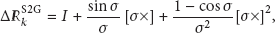

where

However, small offsets in the gyroscope signal accumulate during the integration, which is known as a drift problem. Drift is corrected by fusing the gravity and Earth's magnetic field sensed using a Kalman filter [9, 10]. In particular, the system model for human-motion tracking is described well in [9]. For self-completeness, the orientation estimation can be summarized as follows (Figure 3).

Kalman filter structure. The gyroscope signal,
The accelerometer, gyroscope, and magnetometer sensor signals (
where
The acceleration and magnetic disturbance are modeled into a Markov process model with white driving noise and a constant of between 0 and 1, as in

In this indirect Kalman filter, the error state including the orientation, gyroscope offset, and magnetic distortion,

After the error state is estimated, it is added to the state estimation. With an estimated orientation of θ, included in the estimated state, the acceleration and magnetic signals in the global frame can be estimated. Since the estimated orientation has an error, these estimated signals also have an error. This estimated orientation is therefore corrected by comparing the estimated and measured signals with a measurement matrix, as in

where
The error state covariance Q and measurement covariance R matrixes are calculated as in
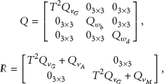
where
With these matrixes, the indirect Kalman filter estimates the current state from the previous state and state transition matrix A. The covariance of the estimated state error P is also estimated as in (9).

Finally, the measurement is updated as in
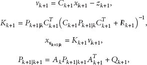
where
These procedures from (1) to (10) are repeated when the sensor signals are received. They are programmed with MATLAB scripts and converted into C files using a codegen tool (MATLAB7.12, Mathworks). The converted C files are included and compiled as a PC application, which includes the motion-tracking algorithm and rehabilitation content. The execution time of the orientation algorithm with a Kalman filter was measured to be about 0.03 ms on a PC (3.0 GHz dual-core Pentium with 2.0 GB of RAM).
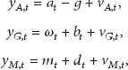
With the estimated orientations and predefined segmental lengths, the positions of the upper arm

where
4. Upper Extremity Rehabilitation Program
The upper extremity rehabilitation application was programmed using Visual C++ 6.0 (Figure 4). The virtual reality platform used to express three-dimensional movement of the upper extremity and the two-dimensional upper extremity rehabilitation program were implemented using OpenGL.

Virtual-reality-based upper extremity rehabilitation program. A conceptual drawing (a) and the simplified version used in this study (b).
The rehabilitation content was designed to provide both training and evaluation at the same time. The content included various dynamic movements and static holds and provided them to the subject within the virtual environment (Figure 5). The dynamic movements consisted of various movements such as shoulder flexion, abduction, adduction, and elevation; elbow flexion and extension; and forearm pronation and supination. The evaluation algorithm was derived from well-established methods including the Upper Extremity Motion Score [11] and Fugl-Meyer Assessment Scale [12]. The static holds were designed to maintain the arm position for a certain period after stretching and lifting the arms and were evaluated based on the National Institutes of Health (NIH) Stroke Scale [13] and the European Stroke Scale [14]. Based on these rationales, the functionality of each subject was evaluated for its spatiotemporal aspects. The average positional difference (

Training content examples: (a) static hold, (b) linear movement, and (c) circular movement.
5. Feasibility Test
To verify its functional feasibility, the system was applied to five healthy subjects (26–30 years old, all male). To simulate a stiff elbow, which is a poststroke complication, the elbow of each healthy subject was taped to restrict its range of motion (Figure 6). The figure shows the system configuration for both the normal group and the group with a simulated stiff elbow [15, 16].

Subject conditions: (a) normal condition and (b) stiffness simulated by taping the elbow.
The linear and circular movements were provided within the virtual environment. The subjects were asked to follow the provided trajectories as best they could. The linear movements were provided in eight directions (Figure 5(b)), whereas the circular movements were provided in the CW and CCW directions (Figure 5(c)). Each movement was repeated ten times for each subject. The values of
Figure 7 shows the hand position trajectory for both the normal and stiff-elbow simulated groups. It was observed that the trajectory under a simulated stiff-elbow condition was qualitatively rougher than the trajectory under normal conditions.

Trajectory example: (a) linear and (b) circular movements. The black line, blue rectangles, and red circles correspond to the training trajectory provided, the tracked positions under normal conditions, and the tracked positions for the stiff-elbow simulated group, respectively.
Table 1 summarizes

6. Conclusion
In this study, an extremity rehabilitation program was proposed based on the use of IMUs and a virtual-reality system. The IMUs were used to track the subject's hand based on its calculated orientation and segment lengths with forward kinematics. In addition, the training content, including various dynamic movements and static holds, was designed to evaluate the spatiotemporal aspects of the subject's functionality. To quantitatively differentiate the evaluations, the proposed system was tested on both a group of healthy subjects and a group of subjects with a simulated elbow stiffness achieved by taping the elbow.
Using the upper extremity rehabilitation system developed in this study, we anticipate that patients will be able to undergo upper extremity rehabilitation on their own without the help of a therapist. Furthermore, a subsequent evaluation of the upper extremity function can be conducted by selecting an appropriate training program; this will increase the effectiveness of their rehabilitation. In future studies, the validity and reliability of upper extremity rehabilitation programs will be assessed for patients with a poststroke upper extremity hemiplegia. Three-dimensional upper extremity rehabilitation programs will be developed to ensure more accurate rehabilitation training for various upper extremity movements as displayed three dimensionally.
Footnotes
Acknowledgments
This work was supported by the Technology Innovation Program (project no. SA113286) funded by the Small & Medium Business Administration (SMBA, Korea) and by the Basic Science Research Program through the National Research Foundation of Korea (NRF) funded by the Ministry of Education, Science and Technology (2013-026506).