
Abstract
As is well known, shaft lining fracture is the main disaster resulting in a large amount of fatalities and property loss. Thus, the additional strain is a key parameter to evaluate the safety condition of existing shaft linings. In this study, a new type of safety monitoring system based on differential resistance sensing technology is developed to measure the additional strain in shaft linings. In this paper, the theatrical study, the working principle, and the function of the newly developed monitoring system are fully presented. To investigate the reliability and effectiveness of the monitoring system, the differential resistance sensors are used to measure the horizontal and vertical strains at different elevations in a shaft lining during reinforcing the fracture inside the shaft lining. It can be found that from the test results the monitoring system based on differential resistance sensing technology can measure the deformation of the existing wall lining during stratum grouting. Therefore, it can be concluded that the newly developed monitoring system is significant for fracture warning and reinforcement engineering.
1. Introduction
Nowadays, more and more large-scale civil infrastructures are being constructed in prosperous cities [1]. These structures are susceptible to random vibrations in their long service period whether they are from changes in temperature, severe wind gusts, torrential rain, strong earthquake tremors, or abnormal loads such as explosions. The coupling effects between these natural or man-made factors make the problem even more complicated. Although the routine visual inspection is effective in some cases, its effectiveness in finding the possible defects in time is questionable. Therefore, it is imperative that a continuous structural health monitoring (SHM) system be developed [1, 2]. Shaft lining is one kind of large-scale civil infrastructures. Since 1980s, the disasters of shaft lining fracture have repeatedly taken place at digging in east China, which greatly threatened the production and safety of collieries. According to the data, there are more than 100 shaft linings with similar fracture, which has caused a large amount of property loss and remains a great deal of potential troubles. The depth of these vertical shaft linings is commonly ranging from 400 to 1000 meters. When the fracture happened, the falling of broken concrete caused casualties and damage to equipments. According to the existing results, the mechanism of shaft lining fracture had been found. China University of Mining and Technology puts forward the vertical additional stress theory on the shaft fracture, which can describe the main characters of the shaft fracture and is gradually accepted by the specialists and scholars home and abroad because it has been supported by many results from theories, experiments, and practical researches [3–5]. Because mining leads to the drainage of the bed of aquifer at bottom of overburden and the dropping of water table, the effective stress of the aquifer increases. These cause the settlement of strata and axial additional force acting on the shaft lining. It is proved that the axial additional force is a main factor leading to the fracture of shaft lining [6, 7].
According to the additional stress theory, to achieve the early warning of fracture, it is important to measure the additional strain and additional stress of shaft lining and get the information of its stress state and trends real time dynamically. Based on the fracture mechanism, it can be found that grouting certain range soil around the lining is an effective reinforcement technique, as shown in Figure 1. In the grouting reinforcement process, the injection pressure can cause the alluvium uplift, which may result in lining subjected to vertical tensile stress and fracture even, and the concrete lining is also susceptible to compress fracturing along the ring. In order to avoid secondary lining fracture, to ensure the normal mine production, real-time monitoring of the stress is needed. From the literatures, it can be found that the frequency strain gage had been tested and utilized in shaft lining engineering, but the effect and durability are poor. In this paper, the authors describe the application of the differential resistance strain gauges in shaft lining safety monitoring system including system components, basic principles, system advantages, and wide applications, and this distributed automatic monitoring system has made a solid foundation for the realization of lining fracture hazard warning; finally, some prospects about this system needed for further study have also been presented.

Stratum reinforced by grouting.
2. Composition of Shaft Lining Health Monitoring System (SLHMS)
2.1. The Differential Resistance Sensors
The sensors are important to the safety monitoring system of shaft lining. The differential resistance sensor has inherent advantages over other electric sensors including high sensitivity, large measurement range, high accuracy, and good stability in long-term monitoring. In addition, the differential resistance sensor with small size (
As shown in Figure 2, the sensing unit of the differential resistance sensor consists of two pretension steel wires connected with two ceramic blocks. The tensile force can be determined by the maximum tensile strain and the strength of steel wire.
Working principle of the differential resistance sensor.
The colors, black, red and white, of cables are designed respectively. Their arrangements are shown in Figure 3. So the resistance

Resistance effect of the differential resistance sensor.
In order to decrease the resistance of sensor's extending cable, we used the following scheme, as shown in Figure 4.

Sensing principle of the differential resistance sensor.
The measured strain can be expressed by

2.2. Arrangement of the SLHMS
To mine the potential of sensors, the optimization of sensor placement is a hot issue for structural health monitoring especially for high rise buildings [8, 9]. In this study, four measurement points at four elevations as shown in Figure 5 were monitored according to the geological investigation. Three measurement points were in the soil mass while one point was at the interface between soil mass and rock bed. As shown in Figures 6 and 7, two differential sensors were used to measure the displacements in two directions at one measurement point.
Schematic illustration of the measurement project.

Layout of measurement points at the same elevation.

Structure of a typical measurement point.
The sensors were buried in the shaft lining at different levels along the vertical directions. The size of the sensor
Flow chart of the monitoring system.
3. Advantages of the SLHMS
All of the sensors data collection was based on computer controlling system. The results can be displayed on the computer screen after data processing software was programed by the computer. It can get the developing status and tendency at any time as the system can maintain 24-hour continuous monitoring. The sensing system possesses features of stability behavior, high precision, and reliability for long term, and each sensor can measure strain and temperature simultaneously, which can simplify the system. It has several advantages such as electromagnetic interference resistance, stability for long-term monitoring, and large working temperature range (from −25°C to +60°C). The sensors buried in the wall can have more than 10-year service life, especially suitable for long-term monitoring.
Based on theoretical analysis, numerical simulation, model test and field measurement conducted by China University of Mining and Technology, the monitoring system can automatically give an alarm once the actual value overrides the set value. System has the function of data remote transmission and the realization of data exchange between single user and data analysis center.
4. Applications of the SLHMS
4.1. Monitoring of Anomalies and Possible Damage/Deterioration
A coal mine has the depth of 462.1 m and the diameter of 6.0 m. The overburden section was excavated by freezing method and the shaft concrete. The inner layer has the thickness of 0.4 m and the outer one has the thickness of 0.4 m too. For the bedrock section, the shaft lining was composed of one-layer concrete with thickness of 0.4 m.
In its long service period, the shaft lining's stress state has been changing. As shown in Figure 9, we have obtained the evolution of the additional strain in 3 years. According to the curve, especially the substantial changes of additional strain and its evolution trend, we can judge whether the shaft lining is safe or not.

Measured value of shaft lining's additional strain in 3 years.
The shaft lining structure is axisymmetric. Based on the existing research results, we can easily detect anomalies in their operational period and possible damage/deterioration at an early stage when knowing well the load condition, stress value, and strength value.
Besides the above, we can also adopt the rescaled range analysis method as follows [10].
The dynamic analyses process for shaft additional strain is as follows: the corresponding time series is


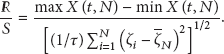


Generally speaking, the shaft additional forces variation consisted with the past variation, and the maintenance is stronger with the increase of the H.
4.2. Process Control during Stratum Grouting for Ensuring the Safety of Shaft Lining
Once a circumferential microcrack appears in the shaft lining, it is on the verge of fracture. To avoid further destruction, the stratum grouting method is used to prevent the shaft lining from fracture as follows [11–13].
The reinforcing engineering is to change the stratum characters by means of grouting and consolidating the bed of aquifer. The purpose is to use the grouting with consolidation performance pouring into holes, cracks in the stratum directly, and squeezing or replace the water in strata in order to compact and raise the stratum. This method can decrease the settlement of the stratum, while the water table is decreasing, and eliminate the additional force. Stratum grouting can not only reduce the additional strain of lining caused by stratum, but also release the existing vertical strain slowly.
Although stratum grouting for the bed of the aquifer has the advantage of restraining and releasing additional strain, it brings the weak side, that is, the stability of shaft lining during stratum-grouting. The improper range, techniques, and parameters of grouting may cause damage to the shaft lining. For example, because the grouting pressure may lead the horizontal pressure acted on lining to excess the designed one, the shaft lining can be damaged. Due to the excessive stratum uplifted and the excessive release of additional strain, the shaft lining will be tensioned in the vertical direction, and its stability will be threatened. So the parameters of stratum grouting must be adjusted in time and the grouting process must be controlled through monitoring the change of the additional strain of shaft lining.
In order to ensure the stability of shaft lining during stratum grouting and to inspect the grouting effect, it is necessary to monitor timely and dynamically the shaft lining stability by setting up a health monitoring system to gather the additional strain values. Based on the evolution of additional strain, the stratum grouting process can be controlled by adjusting the grouting parameters. The controllable parameters in grouting process include the grouting position, pressure, volume, and the density of grout.
Figure 10 is its principle. The stress condition will be changed after stratum-grouting. Because the consolidation of cement slurry entering strata will uplift the stratum, there will be the relatively compressive and tensile strain in the shaft lining, which is the additional strain. By monitoring the additional strain of the key points of shaft lining, we can obtain the changing law of the additional strain and judge duly the stability of the shaft lining. So we can effectively control stratum grouting process.

Working principle of controlling stratum grouting process.
Based on the analysis of the strain state at different points of the shaft lining, we can determine the allowable value of the additional strain
During grouting, we must always comply with the principle of timing, quantification, and interval. According to the evolution of additional strain of shaft lining, we must duly change the parameters of grouting process, such as the grouting order, pressure, volume, and the density of grout, so as to make sure the stratum around shaft lining lifts uniformly.
4.3. Monitor the Repair with the View of Evaluating the Effectiveness of Maintenance and Repair Work
Based on the measured data, we can evaluate the effectiveness after grouting. Figure 11 is a duration curve of shaft lining's additional strain increasing during grouting. According to the shaft concrete properties and strain increment, especially its changing trend, we can also evaluate its safety and service life. Generally, the much flatter the curve is, the longer the service life of the shaft lining could be obtained.

Variation of additional strain in shaft lining during grouting.
5. Conclusions
In this study, the following conclusions can be drawn.
Differential resistance sensor is reliable and efficient for measuring the additional strain in shaft lining, especially for long-time monitoring. The safety monitoring system is necessary for the shaft lining in thick alluvium. The case study presented that the stress of shaft lining measured by the monitoring system can measure the stress changes in shaft lining. The monitoring results show that grouting for reinforcing stratum can effectively reduce the axial additional strain of shaft lining. It can prevent and cure the fracture of shaft lining. According to the evolution of additional strain, it is feasible and effective to control the grouting process and ensure the safety of shaft lining. Further study is needed to study the relationship between the additional strains and related various parameters.
Footnotes
Acknowledgments
The financial supports from the Major State Basic Research Development Program of China (973 Program) no. 2012CB026103, the National Natural Science Foundations of China no. 51104149, and Postdoctoral Special Fund of China no. 2012T50532 are acknowledged. The authors would like to express their deepest gratitude to Professor Guoqing Zhou and all his group members for their great contribution to the work.