
Abstract
The backward-facing step is practically implicated in many devices, encountering the massive separation flows. In the present study, simulations of supersonic flow over a backward-facing step have been carried out employing both RANS and LES. The simulated results are validated against the experimental data. The results of RANS and LES show a good comparison with the experimental results. Different inflow Mach numbers and expansion ratios are also investigated. The reattachment length decreases with the increase of inflow Mach number. The duct height has a great effect on the flow patterns. The present conclusions are helpful to understand the physics in supersonic separation flows and also provide theory basis for engineering applications.
1. Introduction
The flow over backward-facing step is one of the important prototypes used to study the separation flows. Both fundamental experimental and numerical studies have been carried out by many investigators. An experiment was conducted on fine structures of supersonic laminar/turbulent flow over a backward-facing step as discussed by Chen et al. [1]. They found that the supersonic turbulent flow over a backward-facing step had a larger expansion angle and a shorter recirculation region than the supersonic laminar flow. Le et al. [2] found that the velocity-pressure and viscous diffusion are negligible in the shear layer, but both are significant in the near-wall region by direct numerical simulation of the backward-facing step. Neumann and Wengle [3] have applied a passive control approach to investigate an unsteady separated flow numerically. They found increased values for the velocity fluctuations in the primary recirculation zone especially close to the step. So far, the backward-facing step has been developed as a benchmark for evaluating turbulence models for separated flows.
Researches in earlier years were mainly focused on incompressible flow as discussed by Armaly et al. [4], Thangam and Knight [5], Chiang et al. [6], and Nie and Armaly [7]. However, with the development of scramjet engine, backward-facing step as the flame holder has drawn more attention in combustor design due to its simple geometry. The backward-facing step can generate recirculation zones with low flow velocity and prolong the residence time of the flow formed in the step corner as discussed by Halupovich et al. [8], Takahashi et al. [9], and Mitani and Kouchi [10]. Recently, Huang et al. [11] have investigated the flame-holding mechanism in the combustor. They found that the vortices formed in the corner region of the backward-facing step and in the cavity make a large difference to the enhancement of the mixing between the fuel and the free airstream and improve the mixing and combustion efficiency in the supersonic flow.
The supersonic flow over a backward-facing step is relatively complex. Besides that, the turbulent boundary layer separates at the base corner and forms a free shear layer, which reattaches the bottom wall eventually; there also exist expansion fans, oblique shock waves, and reattachment shocks due to the variation of geometry configuration. Because of the complexity of the flow physics, it brings a lot of problems in both experimental and numerical studies. A number of experimental investigations have been carried out using various methods such as laser Doppler velocimetry and planar laser-induced fluorescence as discussed by Hartfield et al. [12], Shen and Ma [13], Furuichi et al. [14], and Tinney and Ukeiley [15]. For numerical study, detailed simulations have been performed by solving Navier-Stokes equations. However, suitable turbulence models and high ordered numerical schemes must be employed to obtain a good resolution of flow fields. Correa and Warren [16] adopted explicit McCormack scheme and k-∊ model to simulate their experiments of supersonic sudden expansion flow. Yang et al. [17] performed a detailed theoretical investigation of the flow structure in a supersonic flow over a backward-facing step, and they employed a flux-vector splitting lower-upper symmetric successive over relaxation (LU-SSOR) scheme to solve the governing equations numerically and algebraic eddy-viscosity model of Baldwin-Lomax for turbulence closure. They got reasonable agreement between calculated results and the experimental data. Manna and Chakraborty [18] have studied the supersonic turbulent flow over a backward-facing step numerically using k-∊ model, and with a finite volume approach, the simulation captured all the essential features of the flow field.
The physical mechanism of supersonic flow over a backward-facing step is complicated and needs to be explored more in depth. The effects of different inflow Mach numbers on flow fields and the variations of flow patterns with different expansion ratios are limited in the open literature. In the present work, the supersonic flow over a backward-facing step has been numerically investigated using both RANS and LES methods. The predicted results show that LES obtained better comparisons with the experimental data than RANS, especially for the velocity predictions. Despite the existing discrepancies which will be discussed later, they are generally in good agreement with the experiment. The effects of inflow Mach number and expansion ratio on reattachment length are then studied.
2. Methodology
2.1. Governing Equations
In this work, the full three-dimensional Navier-Stokes equations in a conservation form for compressible flows are solved, and the general form can be expressed in Cartesian coordinates as

where

are the conservation variables, and

are the inviscid flux, and
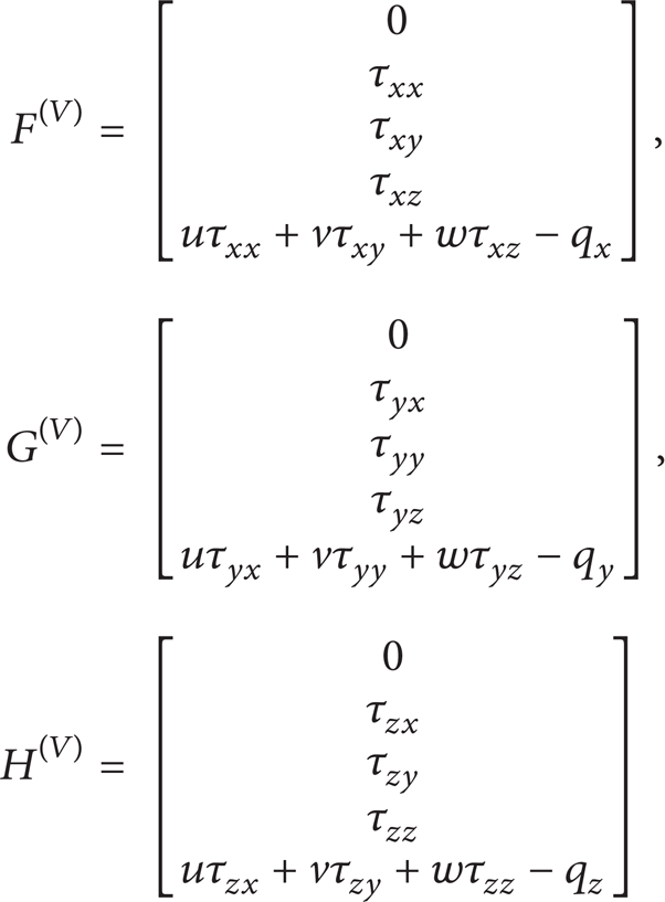
are the viscous flux, and S is the source term.
The total energy is given by

where k is the turbulent kinetic energy and then the state equation can be expressed as
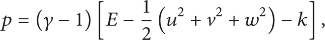
and γ is the ratio of specific heats.
The stress τ ij is given by
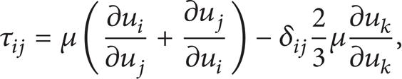
where δ ij is the Kronecker delta and the viscosity μ is calculated through Sutherland's Law.
The transport of heat q i is calculated using Fourier's Law of heat conduction:

where λ is the thermal conductivity, and it was obtained by specifying the Prandtl number, where

2.2. Turbulence Modeling
In this work, we present two different RANS models which are k-∊ and k-ω turbulence models while Smagorinsky SGS model is used for LES. Considering the compressibility in supersonic flows over backward-facing step, the compressibility correction has been introduced to the turbulence models, basically incorporating the influence of the turbulence Mach number into the numerical simulation. The turbulence models of k-∊ and k-ω are given as follows, respectively.
2.2.1. k-∊ Model
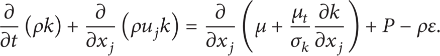
Turbulent kinetic energy equation is as follows:
Turbulent kinetic energy dissipation rate equation is as follows:

where

Turbulent viscosity coefficient is computed as

The coefficients involved in the calculation of μ t are taken as
2.2.2. k-ω Model
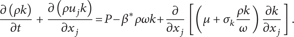
Turbulent kinetic energy equation is as follows:
Specific dissipation rate of kinetic energy equation is as follows:

Turbulent viscosity coefficient is computed as

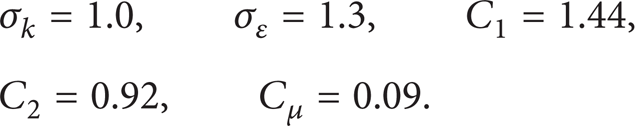
The coefficients involved in the calculation of μ t are taken as

2.2.3. Compressibility Correction
Despite Morkovin's hypothesis that the effect of density fluctuations on the turbulence is small compared with the mean density, there are limitations to the usefulness of this hypothesis with the Mach number increasing. The turbulence Mach number M t which describes the turbulence intensity in supersonic flow is given as M t 2 = 2k/a2. Building upon the Sarkar/Zeman formulations and dimensionless analysis, Wilcox has postulated the compressibility correction model as discussed in [19]:

The closure coefficients β and β* in the k-ω model vary with M t ; then they can be rewritten as
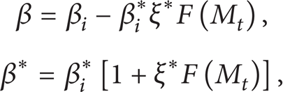
where β i and β i * are the corresponding incompressible values of β and β*, ξ* = 2, M to = 1/4, and H(x) is the Heaviside step function.
2.2.4. Smagorinsky SGS Model
Smagorinsky SGS model expresses the SGS viscosity in an explicit way derived from the concept of phenomenology as discussed in [20], which is based on the Boussinesq hypothesis assuming that the behavior of the subgrid scales is analogous to molecular motion drawing energy through molecular viscosity, and local equilibrium hypothesis assuming no accumulation of energy at any frequency.
Consider

where C
s
= 0.18,
In the present simulations, the equations are solved utilizing a finite difference approach. The inviscid flux is discretized by applying Roe-Type Riemann solver, and the second-order spatial accuracy is obtained by using the MUSCL-type scheme. To avoid unrealistic solutions caused by the Roe-type Riemann solver, a modified Harten-Hyman entropy condition is used. The viscous flux is discretized by a central difference scheme. A two-step Runge-Kutta method is used to integrate the equations temporally.
3. Results and Discussions
The calculation physical model is chosen corresponding to the experiment as discussed by McDaniel et al. [21]. Detailed measurements of flow parameters in the experiment were carried out using laser-induced iodine fluorescence (LIIF) and planar laser-induced iodine fluorescence (PLIIF) techniques. The calculation domain is shown in Figure 1, where H (21.29 mm) is the duct height and h (3.18 mm) is the step height. The inflow conditions in the experiment are given in Table 1. In the present simulations, the inflow boundary conditions are the same as the experiment, the outflow boundary is treated using extrapolation, and no-slip wall condition is employed.
Inflow boundary conditions.


Computational domain.
Figure 1 also gives a schematic description of the backward-facing step flow field in supersonic condition. The supersonic stream expands at the base corner and forms the expansion fans. The turbulent boundary layer separates and forms a free shear layer which divides the main flow with the recirculation region [22, 23]. With the development of the shear layer, it reattaches the bottom wall and the reattachment shock wave appears. After the shock wave, the pressure is increased and part of flow in the shear layer flows backward to the step corner due to the increasing pressure and forms the recirculation region.
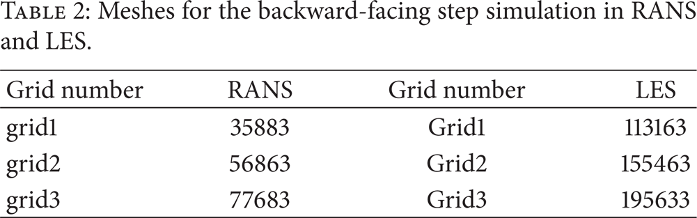
The mesh independence of the results is demonstrated using three different grids for RANS and LES, respectively. The grid number for different methods is presented in Table 2. In the present work, the simulation of k-∊ and k-ω turbulence models is carried out on the same meshes, namely, grid1, grid2, and grid3, and the meshes for Smagorinsky SGS model are Grid1, Grid2, and Grid3. The streamwise velocity distributions at 10 mm downstream from the step for RANS and LES are shown in Figure 2. It can be seen that the results do not change appreciably both for the two methods by increasing the number of grids, proving the mesh independence of the results. Considering the accuracy and the computation cost, grid2 for RANS and Grid2 for LES are chosen in the following study.
Meshes for the backward-facing step simulation in RANS and LES.

Mesh independence of the results.
Most of numerical investigations for the backward-facing step in supersonic flow are based on either RANS or LES [10, 11, 18, 24–26]. RANS can give the averaged parameters of the flow field and predict the large-scale fluctuations through modeling, while LES is supposed to be more accurate theoretically, provided that only the subgrid scale eddy should be modeled according to the basic hypothesis of LES that the sub-grid scale is isotropic, and the larger eddies are calculated using Navier-Stokes equations. Though both RANS and LES are optional methods for the supersonic backward-facing step problem, the comparisons between them are rarely seen in the literatures. In this paper, results of the k-∊ and k-ω turbulence models, which are the most popular RANS models in the past few years and have been extended to compressible flows by considering the compressibility correction as discussed in Section 2.2.3, are obtained and compared with the LES results of the Smagorinsky SGS model.
The numerical results using different turbulence models are validated against the experimental data. The velocity profiles, static pressure, and temperature profiles at two different streamwise locations, namely, x/h = 3.0 and 6.66, are compared with the experimental data as shown in Figure 3. The predicted profiles are generally in good agreement with the experimental data at both locations for RANS and LES. For the velocity comparisons, the results near the wall for LES show better agreement with the experimental data than those for RANS, while the results of k-∊ and k-ω turbulence models have little difference. For the static pressure profiles, it can be seen that results of k-ω model near the wall are in better agreements with the experimental data than the results of k-∊ model. The boundary layer separation due to the reattachment shock may be the cause for this difference. Because of the increasing pressure after the shock, adverse pressure gradient along the bottom wall exists, and the k-∊ model has been demonstrated to be inadequate for simulations under this condition, but the k-ω model is more suitable for such flows [27–30]. It is also observed that the results of LES match well with the experimental data, though there are some discrepancies near the wall at x/h = 3.0 located in the vicinity of the recirculation zone. They are attributed to the grid inadequacy considering that the Smagorinsky SGS model is built upon phenomenological hypothesis and the grid size should be based on the local inertial range, which is impractical for such a complex recirculation flow and also indicates a huge increment in computation cost. For the static temperature profiles, the LES results are also shown to be more accurate in comparison with the experimental data than the RANS results, but they are comparable in predicting the temperature distributions for the present backward-facing step problem.

Comparisons between numerical results and experimental data at different locations.
Through the above comparison, it can be seen that both RANS and LES give a good description of the supersonic flow over a backward-facing step, and LES shows to be better when compared with the experimental data, though the differences between the two methods are small. In RANS, as discussed previously, the k-ω model is more capable of such kind of separation flow with adverse pressure gradient. In LES, the accuracy of the results is sensitive to the grid number, and as a result, more attention should be paid to the grid construction, especially for the regions with complex flow features.
The turbulence intensity near the bottom wall and top wall at three different streamwise locations, namely, x/h = 1.75, 3.0, and 6.66, is plotted in Figure 4.
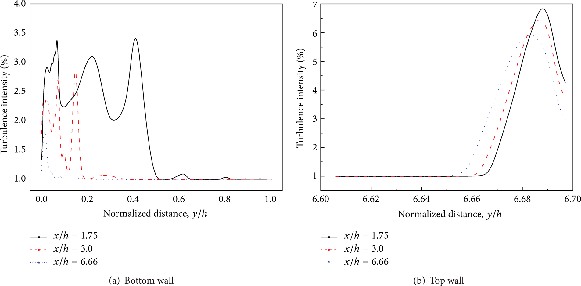
Streamwise turbulence intensity profiles at different locations.
There are three peaks for the profiles at x/h = 1.75 and 3.0 near the side of bottom wall as shown in Figure 4(a). Since flow with velocity gradients can easily lead to production of the turbulent kinetic energy which can be concluded from (10), the no-slip wall and the recirculation zone may contribute to the three peaks: the left one is caused by boundary layer flow due to the velocity stagnation on the bottom wall. As can be expected, the recirculation zone is a flow structure with large velocity gradients. Therefore, the middle one should be formed from the lower part of the recirculation zone, and the right one should be formed from the upper part of it near the free shear layer as shown in Figure 1. With the increasing of x location, the recirculation zone becomes thinner in y direction, so the three peaks become closer to the bottom wall for x/h = 3.0, comped with the profile of x/h = 1.75, and finally when the x location is beyond the recirculation zone, only one peak exists in the profile of x/h = 6.66. Therefore, it can be noted that the recirculation zone is the main source for turbulence, which is helpful for the mixing when the backward-facing step is used in the combustor design. The profiles of the three different streamwise locations near the side of top wall are shown in Figure 4(b). The only one peak for each profile is supposed to be accounted for by the velocity stagnation on the top wall. The attenuation of the turbulent kinetic energy may be explained as the boundary layer develops and the velocity gradient becomes smaller. For a close inspection of the turbulence intensity, the turbulent kinetic energy near the top wall is larger than that near the bottom wall, since the flow velocity near the top wall is higher than the flow near the bottom wall undergoing expiation, reattaching and separation. Thus, the stagnation on the top wall results in the lager production of turbulent kinetic energy.
3.1. Effect of Inflow Mach Number on Reattachment
The reattachment length is an important parameter in the backward-facing step problem. The reattachment point is determined where the surface velocity is zero and the reattachment length is defined as the length between the step corner and the reattachment point. Typically, both experimental and numerical studies in the past mainly focus on the low Mach number conditions [17, 18, 21, 25, 31]. However, with the hypersonic aircrafts being developed, the investigations of sudden expansion flow in high Mach number conditions such as the airfoil problem have become increasingly important. In the present work, five different inflow Mach numbers varying from 2.0 to 6.0 have been used to investigate the effects of the inflow condition on the reattachment length.
The streamwise velocity profiles on the surface (one grid distance from the bottom wall) for different inflow Mach numbers are shown in Figure 5. The flow velocity has experienced a negative and positive zone. It is clear that the negative one represents the recirculation zone in the step corner. It is easily understood that the higher inflow Mach number may cause stronger reattachment shock, resulting in more severely adverse pressure gradient, which accounts for the boundary layer separation and the formation of the recirculation zone. The high pressure after the shock works on the recirculation zone, pushing it backwards to the step. At first, the reattachment length decreases apparently with the increasing Mach number. However, as the Mach number increases, more and more work has been transformed to the kinetic energy in the recirculation zone, resulting in the increasing absolute velocity and slight changes in reattachment length.

Streamwise velocity profiles near the bottom wall.
Compared with the experimental results of Anatol and Thomke [32] and numerical results of Abdullah et al. [33] shown in Figure 6, the present simulation gives a good prediction of the variation of the reattachment length with different inflow Mach number. There exists an apparent decrease in the reattachment length. However, as discussed above, when the inflow Mach number is larger than 5, the present results show that the increasing Mach number has little effect on the reattachment length.

Effect of inflow Mach number on the reattachment length.
3.2. Effect of Expansion Ratio on Reattachment Length
The expansion ratio is defined as
It is an important parameter for the flame holder design in combustor, which affects the efficiency of mixing and combustion [34–37]. The higher expansion ratio may lead to complex shock reflections and severe boundary layer separations, as to be discussed later, which can yield small cross-section area for inflow air and even causes congestions especially under the combustion condition.
The effects of expansion ratio on the reattachment length are studied by varying the duct height H, and the step height h is kept constant. The profiles of streamwise velocity on the surface (one grid distance from the bottom wall) are shown in Figure 7. The flow experiences the recirculation zone and shear layer reattachment. For the expansion ratios of 0.15 and 0.3, the length of recirculation zone varies slightly with the expansion ratio increasing. However, when the expansion ratio increases to 0.6, the reattachment length has a great decrease. Figure 8 shows the pressure distributions on the surface of bottom wall. It is found that two peaks exist for the case of the expansion ratio 0.6, but for the other two cases, they each have only one peak in the same region. The first peak location shows up closer to the circulation zone as the expansion ratio increases. The predicted Mach number contours and pressure contours after the step of different expansion ratios are shown in Figure 9.

Streamwise velocity profiles near the bottom wall.

Pressure distribution along the bottom wall.

Mach number and pressure contours of different expansion ratios.
As shown in Figure 9, with the duct height decreasing, the number of shock reflections increases, resulting in more peaks in pressure distribution on the bottom wall, which is consistent with the above discussions. As the top wall gets closer to the bottom wall, the expansion for the supersonic inflow is larger. The accelerated flow after the expansion fan reattaches the bottom wall and forms a stronger reattachment shock; thus the boundary layer separation on the top wall caused by reattachment shock becomes larger and closer to the recirculation zone, resulting in narrower flow area in the duct. It also shows that the reattachment point is around at x = 0.012 m and changes slightly when the expansion ratios are 0.15 and 0.3, respectively. But when the expansion ratio comes up to 0.6, the reattachment point is around at x = 0.007 m, so the reattachment length becomes much shorter, which corresponds to the above profiles of streamwise velocity near the bottom wall shown in Figure 7.
4. Conclusions
Numerical simulations are carried out for supersonic flows over backward-facing step using RANS and LES methods. The predicted results are in good agreement with the experimental data. The two RANS models, namely, k-∊ and k-ω models, have little difference in this work, and the Smagorinsky model shows better comparison with the experimental data. Effects of different inflow Mach numbers and expansion ratios on the reattachment length are investigated. It is found that the reattachment length becomes shorter when the inflow Mach number increases. However, this feature for higher values of Mach number is not obvious. The effects of duct height on flow patterns turn to be stronger when the expansion ratio is high, resulting in the decrease of the reattachment length. For small expansion ratios, the duct height has little influence on the reattachment length.
Footnotes
Nomenclature
Acknowledgment
This research was supported by the National Natural Science Foundation of China under Grant no. 51176099.