
Abstract
An embedded system that contains hardware and software was developed for two-axis solar tracking system to improve photovoltaic panel utilization. The hardware section of the embedded system consists of a 32-bit ARM core microcontroller, motor driver circuits, a motion control unit, pyranometer, GPS receiver, and an anemometer. The real-time control algorithm enables the solar tracker to operate automatically without external control as a stand-alone system, combining the advantages of the open-loop and the closed-loop control methods. The pyranometer is employed to continuously send radiation data to the controller if the measured radiation is above the lower radiation limit the photovoltaic panel can generate power, guaranteeing the solar tracking process to be highly efficient. The anemometer is utilized in the system to ensure that the solar tracking procedure halts under high wind speed conditions to protect the entire system. Latitude, longitude, altitude, date, and real-time clock data are provided by GPS receiver. The algorithm calculates solar time using astronomical equations with GPS data and converts it to pulse-width modulated motor control signal. The overall objective of this study is to develop a control algorithm that improves performance and reliability of the two-axis solar tracker, focusing on optimization of the controller board, drive hardware, and software.
1. Introduction
Solar energy is broadly available all over the world free of charge, but it is not a continuous source of energy. Photovoltaic systems are extensively accepted as one of the resources of renewable electricity and employed for conversion of solar energy to electrical energy. The semiconductor PV arrays are actually appropriate for most applications at moderate initial and low maintenance costs.
The widely established photovoltaic applications can be classified as stand-alone, grid connected, and hybrid. These systems are composed of a photovoltaic generator in the form of a cell, module, or array; batteries for energy storage; AC and/or DC loads with special circuitry for power conditioning. In many researches, PV module's performance and maximization efficiency of solar radiation are studied as PV cells have stimulated great interest in solar tracker systems. Photovoltaic generators work most efficiently when the sun is directed perpendicular to their panel surfaces. Using a solar tracker for the PV panel dramatically upsurges the initial and operational costs, but in return this results in an increase in the system efficiency. Mousazadeh et al., Romero et al., Ryu et al., and Saxena and Dutta [1–4] all pointed out that the use of one-axis solar tracking systems can increase the energy output up to 20% with a cost increase of 10%, where two-axis solar tracking systems can increase the energy output up to 40% with a cost increase of about 30%, over a fixed solar system.
Investigations on microcontroller based solar trackers verified that the energy generation has been improved by tracking the sun's position. Today's developments in automatic control systems lead to enhancement of contemporary power generation techniques. Solar tracking is one of the automated methods to best accomplish the task of increasing power output of PV panels by matching the tilt angle of the panel to the seasonal and daily changes of the sun's altitude [5].
To get the most out of the energy output of a PV system, a sun tracker is used to line up the collection system to the changing sun's position in the sky with seasonal variations and time of day. An ideal sun tracker should forward the photovoltaic panel to the sun, by compensating for changes in the sun's altitude and azimuth angles [6].
There are some aspects that should be taken into consideration in determining the use of trackers including the PV technology of the solar panel, the amount of direct solar irradiation, feed-in tariffs in the district where the system is installed, and the installation and maintenance costs of the solar trackers. In standard PV applications, sun trackers do not necessarily follow directly sun's trajectory. A deviation from the target by 10° may cause an energy decrease at the output by only 1.5% [7].
The solar trackers are basically grouped as single axis and two-axis ones. Single axis trackers can either track the sun with a vertical or a horizontal axis. Single axis solar trackers have one actuator and therefore are simpler to control than two-axis solar trackers. As there are small amounts of controlled variables, it is easier to write a control algorithm for the following sun's trajectory. Fewer components also mean lower initial investment on the system. Two-axis solar trackers follow the sun's visible motion anywhere in the world with a trajectory in vertical and horizontal axes. Two-axis solar trackers are more accurate in pointing the sun, but as there are two actuators to be controlled, the number of controlled variables increases causing a more complex control system, both hardware and software [8, 9].
This paper presents an optimized control algorithm for the two-axis sun trackers that can be executed in an ARM based 32-bit microcontroller to specify the optimal trajectories for the tracking system. The algorithm calculates solar time using astronomical equations with GPS data and converts it to pulse-width modulated motor control signal to determine the optimal attitude of the PV panels by evaluating the consumed energy with the gained energy.
2. Two-Axis Sun Tracking
The two components of sun's rays are the ones that are perpendicular and parallel to the surface. Only the incident radiation on the panel that is perpendicular to the surface can be converted into energy. Consequently, the incidence angle that is defined as the angle between the sun's rays and the normal of the panel must be so small that most of the incoming energy from the sun can be efficiently used by the solar panel. It is a known fact that the incidence angle changes on daily basis and also throughout the season. Therefore, the solar panels having no degree of freedom are not fully capable of absorbing the solar radiation. If the solar panels are positioned according to the sun's trajectory by an automatic tracking system to reduce the incidence angle, it will be possible to absorb more energy from the sun than the fixed panels can achieve in the same irradiation conditions. In the dual-axis sun tracking system, the panel rotates around the azimuth and the elevation shafts as shown in Figure 1. This gives the panel a degree of freedom of two to track the sun's azimuth angle and elevation angle to achieve an incidence angle of 0° [10].

Structure of the two-axis sun tracker.
The three methods that are used in solar tracking are the closed-loop control method, the open-loop control method, and a hybrid method comprised of both methods. The common task of all three methods is identifying and trailing the position of the sun between sunrise and sunset periods. The closed-loop control method uses feedback sensors such as LDRs, photodiodes, light-intensity sensors, reference cells, and a signal processing circuit [11–13]. The duty of the signal processing circuit is to compare the sensor's output signal with the desired signal condition producing an error signal. The control on a feedback loop is then achieved by continuously adjusting the tracker direction until the shading on the sensors is minimized. A drawback of the closed-loop control method is that it cannot effectively track the sun on a cloudy day without a robust algorithm. Only few researchers used image sensors coupled with image-processing software to overcome tracking problems on cloudy days [14].
The open-loop control method uses the longitude and latitude data of the solar tracker location to determine and track the position of the sun. It has the advantages of easy programming and high accuracy [15]. The system is simple and cost effective compared to the closed-loop sun tracking systems [16, 17]. In this type of control method, the output of the tracking process that is controlled is not detected by sensors which are used to measure sun's position, so the open-loop control continues even in cloudy weather conditions. However, in this method the tracker needs to be adjusted to a fixed starting position at every sunrise. The starting position of the tracker must be corrected periodically whereas an open-loop control system cannot automatically correct any error that it could make and may not regulate the system for any disturbances [18].
The hybrid method combines the advantages of open-loop and closed-loop methods. Although this method has a high accuracy and precision in tracking the sun, in fact, it has the highest initial cost due to the costly sensors, the complicated structure, and complexity of the program algorithm.
2.1. Defining Elevation and Azimuth Angles Trajectories
The sun tracking algorithm utilizes the elevation, α, and azimuth, Ψ, angles and then computes tilt angle for the examination site where the tracking system will be installed. The tracker must be lined upto vertical and horizontal axes to fix the tilt and azimuth angles accurately with the hour angle as depicted in Figure 3. Solar azimuth, Ψ, is the angular displacement of the projection of the sun onto the horizontal plane from the south axis. On the other hand, α is the angular height of the sun according to horizon.
α is the solar elevation angle that shows the orientation of the system in the vertical plane and can be defined using[19]

where α is the elevation angle of the sun, ϕ is the latitude, ω is the hour angle, and δ is the solar declination. It can be defined using Cooper's equation [20]

where N is the day of the year.
Tilt angel of PV panel, β, can be calculated according to Figure 3

The azimuth angle, Ψ, of the is calculated by using (4) [21]

Trackers are mostly designed to follow the sun path from sunrise to sunset and return to its original horizontal position after sunset. The sunrise and sunset times can be derived using (5) with help of location longitude [22]:

For the time of sunset, the equation is the same, but it is H hours after the local noon. Time conversion from the solar time t s to the UTC clock time and also local clock time (LCT) needs location data, the day of the year, and the local standards to set the local clocks. Solar time t s is converted to local clock time (LCT) as follows:

The parameter D in (5) is used to correct the local time if daylight savings time is effective in that region and it should be taken as 1 (hour), otherwise 0. EOT in (5) is the “Equation Of Time” in minutes which can be calculated using the following equation [23]:
LC (hours) is a longitude correction in hours which is defined as follows:

The developed sun tracking algorithm allows determination of sun angles and times for solar noon, sunrise, and sunset with high-precision year-round using (1) through (8). It takes data that contains date, time, longitude, latitude, and elevation from GPS receiver. The present solar time was compared with the calculated solar time to decide whether the sun tracking procedure would be conducted or not. At night time, it waits for the next sample time. Sample time period may be defined according to GPS hot start time constraints. GPS receivers are available at the market having hot start time from 100 milliseconds to 1 second.
The optimization constraint is the energy consumed by the tilt-angle motor and the azimuth-angle motor during one tracking interval. For one degree of motion, the energy consumption in the tilt-angle motor or azimuth-angle motor can be defined using the motor time-dependent voltage v(t) and current i(t) with

where t depends on motor velocity. The startup current of PMDC motor is at least six times higher than nominal velocity current. So, defining steep angle too small can make energy consumption higher than energy gain especially during cloudy and rainy days. The proposed hybrid algorithm predicts an optimal locus angle for the PV panel automatically at each interval by evaluating energy consumption with predicted energy gain. To predict the energy gain on the target tilt and azimuth angels, the proposed controller uses a pyranometer. The algorithm needs measured time-dependent values of total I h , direct Ib, h, and diffuse Id, h solar radiation on a horizontal plane to determine the tilted solar radiation I c on the surface of a PV module as a function of (t). The solar radiation I c is given by (10) as a function of (t) for given β and Ψ angles:
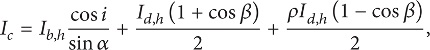
where ρ is the ground reflectance constant, i is the angle between beam and normal of the tilted PV panel. and i is calculated with elevation and azimuth angles by using

where a s is the solar azimuth angle as shown in Figure 2.
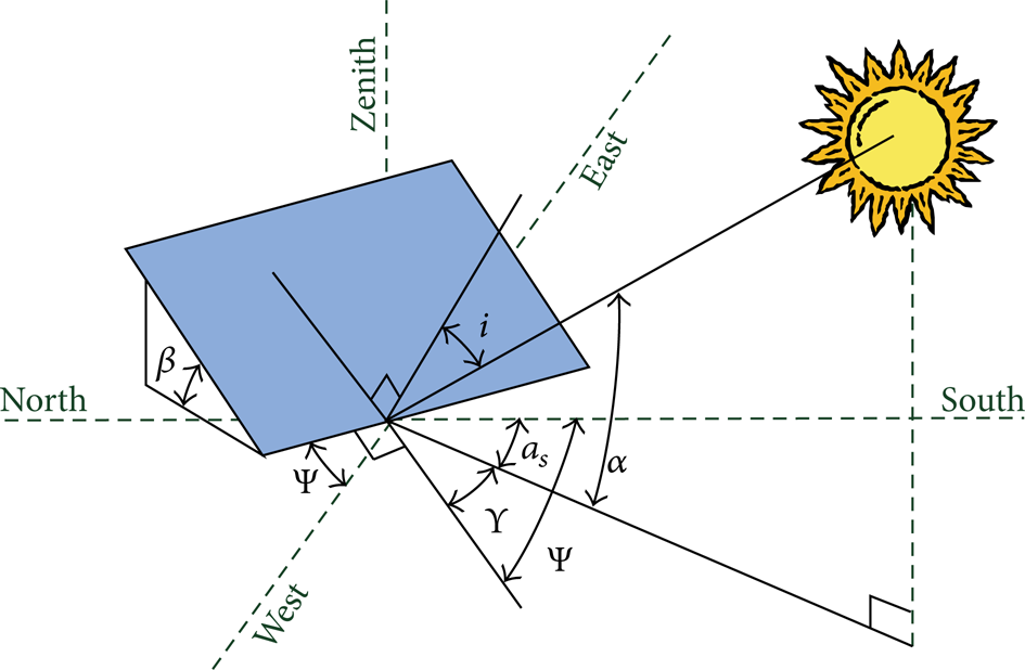
Sun beam incidence angle of the tilted PV panel surface.
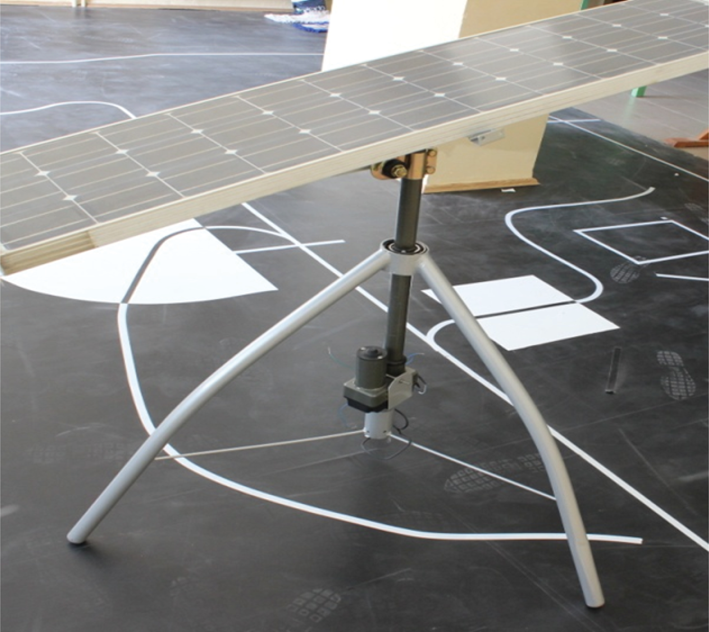
Mechanical structure of the sun tracker.
End of the optimization process of solar elevation and azimuth angles is described as function of (t) during the given period. Using β(t), Ψ(t) global solar radiation on the PV module, Ic(t), is calculated by (10). Regardingthe effective area of the PV panels APV and the efficiency of the PV panels, η, the electric energy EPV, generated by tracker in the period t ∊ [t1, t2], can be calculated by

For optimization of the controller, the problem is how to decide the path of Ψ(t) and β(t), which makes the generated energy maximum in the tracking system, regarding the power consumption during tracking operation. According to the proposed algorithm, for every time interval, energy gain that is acquired by tracking the sun should be two times greater than the power consumption which is consumed by the tracker motors. In the tracking process, the energy is consumed not only for aligning PV panel normal to sun beam but also for ending the process to carry tracker mechanism back to initial position. Omitting energy consumption which is consumed by azimuth- and tilt-angle motors, the continuous sun tracking scheme maximizes the energy output of the tracker and it is called EPV-ideal.
The optimization decision variables matrix, Xdecision, can be expressed in

The operation strategies matrix Xop-strg can be expressed in

The optimization constraints that must be fulfilled are given by
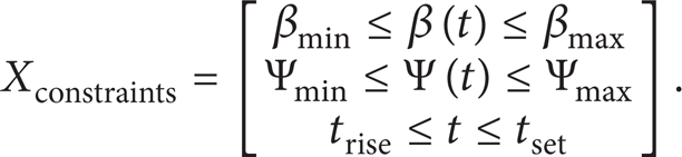
And the objective function f, minimized in the optimization procedure, is given by
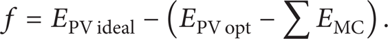
Usually, the observation interval is one day. The discrete time interval is set to 1 second for all time-dependent functions. During the optimization, each iteration step generates new Xdecision matrix by the algorithm andis evaluated with the objective function f and checked for violation of constraints Xconstraints. The new population members in Xdecision, whereas only some of the new members that advance the objective function are stored. The result of the optimization is the matrix Xdecision with the best objective function value. It is used to define the path scheduling for β(t) and Ψ(t), as described previously. The efficiency, ∊, of the tracker which is utilizedin PV system is defined using
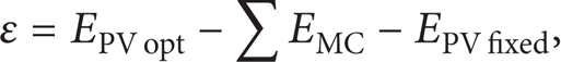
where EPV opt is the optimum electric energy that is generated when using optimized controller operated sun tracking system, while EPV fixed is the electric energy generated in the fixed PV system.
3. Design and Application
The whole sentence “The proposed control strategy differs from the others, that is; used open-loop [2, 7, 11], closed-loop [5, 12–14], and hybrid [24, 25] control strategies are the following.” is revised as “The proposed control strategy that is used differs from open-loop [2, 7, 11], closed-loop [5, 12–14], and hybrid [24, 25] control strategies as stated below.
The systems that use open-loop control strategy have time based error. they need calibration time to time. Developed control strategy can correct time based errors using date-time data inferred from online GPS receiver without calibration.
Those systems that use open-loop and hybrid control strategies need large amount of memory to hold actuators' position lookup table for whole year. However, as desired precision increases, the resulting memory requirement also increases. As our control strategy can calculate the actuators' position using longitude, latitude, altitude, date, and time data gathered from GPS receiver, the need for memory decreases. Additionally, user can define precision without requirement for an extra memory usage.
The closed-loop systems that use electrooptical sensor or image processing for feedback have weakness in cloudy and windy days. As our control strategy takes into account energy saving factors, the actuators never start to track sun unless solar irradiation reachs a certain level that PV panel output power can feed actuators.
3.1. Mechanical Design
Two-axis sun trackers are set up by manipulating robot arms which conserve the direction of the photovoltaic panel toward the sun retaining the line of vision perpendicular to the panel. As the sun moves slowly in the sky (0 < 180°/12 hours), two degrees of freedom for sun following are sufficient. Three-actuator robot design can be considered to lead to better results, but this system is mainly regarded as actuating redundantly in sun trackers. Consequently, one of the design objectives should be to reduce the actuator number to two. Serial tracker architectures consisting of one or two revolute joints ensure the rotational two degrees of freedom. Nevertheless, serial designs have a main disadvantage where a heavy structure is required to support rigidity of PV panels. This leads to a necessity of larger actuators, exceeding optimum power consumption.
In this design of panel support structure, inclination and orientation were varied with two degrees of freedom. The tracker is comprised of a base fixed on the ground, and an apparatus joining the base with three legs to the support of the panels. This two part apparatus is designed to revolve the panel supporting mechanism around two axes. For shifting the inclination of the supporting assembly, additional linear actuator is mounted to the solar tracker control system.
Linear actuators are extremely precise by design, especially when compared to pneumatic and hydraulic solutions. Screw based mechanical linear actuators allow advancing or retreating the motive rod by extremely small increments, which is required for the exact positioning of solar tracker. Electric linear actuator consumes extremely low electricity and is available in 12 Volts Dc that can be powered by the solar panel supported by a battery. Linear actuators can be unusually small, especially when considering the range of motion that is required for moving the sun tracker. Photograph of the mechanical structure is shown in Figure 3.
3.2. Hardware Design
The hardware design combines the embedded microcontroller with two PMDC motor drives, rotational DC motors, DC motor controlled linear actuators, a solar rotation mechanism, a global positioning system (GPS), a pyranometer, an anemometer, tilt switches, and MEMBS based inclinometer. An overall block diagram of the control system is shown in Figure 4.

Sun tracker control system block diagram.
GPS is connected to the microcontroller via a standard serial RS-232 port. GPS continuously sends to the microcontroller sentences that contain a string of characters. These sentences mainly include longitude, latitude, altitude, date, and time for location where GPS is placed. Since microcontroller has the real-time clock circuitry, it is reasonably accurate over short periods, but it needs calibration periodically. As a result, the GPS clock signal is used to update the microcontroller's internal time periodically and thus effects of the long-term errors are eliminated.
As part of the effort to improve solar tracker reliability and better understanding performance, a pyranometer is being added to solar tracker. This pyranometer which is placed on the tracker allows the data acquisition system to measure precisely the irradiance faced by the PV modules, and thus it allows a better monitoring of the impact of the tracking algorithm on the energy output of the system.
Solar tracker measures tilt angle with a potentiometer that has a long-term reliability problem. A higher reliability alternative is a solid-state inclinometer. It has three main advantages: inherently higher reliability, higher resolution less than 0.1°, and direct measurement of angle. In this project, microelectromechanical systems based on electronic inclinometer ADXL345 are used [26]. Digital output data is formatted as 16-bit two's complement and is accessible through either a 3- or 4-wire serial port interface (SPI) or I2C digital interface. The inclinometer would typically be mounted directly underneath a tracker's plane, from where the inclination can be measured.
The solar tracker is fitted with limit switches to ensure robust operation. A microroller switch mounted on the base of the solar tracker prevents multiple revolution windup of the azimuth tracking stage. The solar collector also includes two more limit switches on the zenith tracking stage to prevent over travel damage to the linear actuator mechanism. The initial reset balance uses tilt switches. The mechanism includes four tilt switches (east, west, south, and north). To protect tracker components from over wind speed, system also requires an anemometer to measure wind speed.
Consequently, we need a powerful and cost-effective microcontroller to connect all these parts and manage to track the sun. It must have two serial ports called universal asynchronous receiver transmitter (UART), one for communicating with the computer and the other one for GPS, two pulse-width modulation (PWM) signals for motor A and motor B, one I2C port for solid-state inclinometer, one hardware counter input for anemometer, an analog input for pyranometer, and at least four digital inputs for tilt switches. In addition, these features are needed on behalf of software development tools for microcontroller. Regarding the aforementioned calculations, 32-bit Stellaris microprocessor LM3S811, which is optimized for small footprint embedded applications, fits best to the sun tracker system. TI Stellaris LM3S811 microcontroller has the followingfeatures: a Reduced Instruction Set Coding (RISC) ARM core, internal oscillators, timers, watch dog timers, USB, SPI, UART, PWM, ADC, and analog comparator [27].
3.3. Software Design
The developed sun tracking algorithm allows determination of sun angles and times for solar noon, sunrise, and sunset with high-precision year-round. The flowchart of the algorithm is drawn in Figure 5. The calculation of the sun angles with the sun tracking algorithm software simply requires the specification of the date, time, precise longitude, latitude, and elevation of the location through a GPS system.
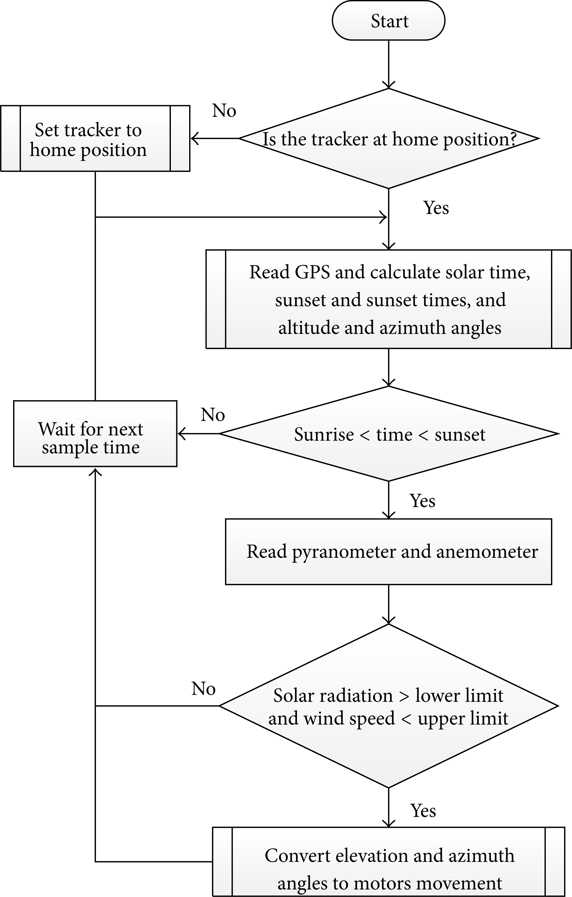
Flowchart of sun tracking algorithm.
When the system starts, Stellaris first sets tracker to the home position and then takes GPS data to calculate the sunset and sunrise times. The present solar time was compared with the calculated sunrise and sunset times to decide whether the sun tracking procedure would be conducted or not. At night time, it waits for next interval. Discrete time interval may be defined according to GPS hot start time. It is 1 second for GPS that is used in this study. If the present solar time is between sunrise and sunset times, microcontroller reads anemometer value to define whether the sun tracker can move safely. Under the 12 m/s wind speed sun trucker works in tracking mode, otherwise it stands table position to save the tracking system. During the tracking phase microcontroller reads pyranometer value to check if there is enough solar radiation to generate power. Otherwise, sun tracker stays at home position until solar radiation rises to lower limit of solar radiation. After solar radiation reaches the desired value, then algorithm calls optimization subroutines. Optimization subroutine calculates the optimum Δβ and ΔΨ angles values and calls PID position control subroutine.
PID position control subroutine takes azimuth, ΔΨ, and tilt, Δβ, angles and converts them to PWM signal to give motion to the tilt and azimuth motors. The calculated angles β(t), Ψ(t) are then subtracted from the previous position values. According to the obtained angle difference and their signs, microcontroller sends PWM and direction signals to the motor controllers. Azimuth and tilt motors take solar panel to the new position to precisely track the sun. The electronic inclinometer ADXL345 sends x-, y-, z- and axis values to Stellaris. This digital axis values are converted to angles by the microcontroller. By comparing the measured angles with calculated angles, the two motors take different movements to come up to the desired position of the solar panel. When the sun sets at the end of the day, the system returns to the home position, ready for the next sunrise.
4. Results and Discussions
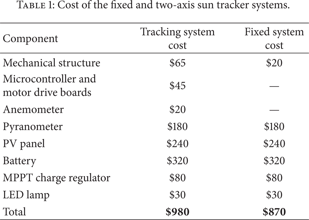
The designed two-axis solar tracker with PV panel and a fixed PV system which is tilted to latitude of the place whole year are used in this test study. Siemens SM-55 monocrystalline PV panels are used in the two-axis and fixed PV systems. The technical characteristics of the PV panel are given in [22]. All experiments presented in this section are implemented for the coordinates 38°27.0′ N, 27°13.2 E. During the test process, fixed and tracking solar panels' outputs were connected to separate but equal 12 V, 90 Ah gel batteries using maximum power point tracker (MPPT) charge controller as shown in Figure 6. The solar irradiance is measured by using a Li-Cor LI 210SA pyranometer [23]. The PV voltage VPV, current IPV, battery voltage V B , battery current I B , and sun trucker current, IST were measured and stored every minute using a data logger during the test process with an interval of 1 second. The energy generated in a day or an hour could be obtained by integrating the maximum power along this period of time. Both systems charge the battery on day time and at night time; this stored energy feeds examination loads that are two 12 V 24 W LED lamps. The cost of the components and the total cost of the sun tracking and the fixed PV systems are given in Table 1. The total cost of the sun tracker is found to be 21.1% higher than that of fixed PV system.
Cost of the fixed and two-axis sun tracker systems.

Testing bench of two-axis sun tracker.
Fixed PV system and two-axis sun tracking system were tested from the beginning of January 2013 to end of May 2013. Every week, data logger was uploaded to the computer. Using this collected data, daily variations of the PV panel output currents are drawn as shown in Figure 7 for fixed and tracking systems. At the end of the day, the solar panel charged the battery up to 408.2 Watt-hour energy for about eleven hours. The recorded data May 5, 2013, proved that the two-axis solar tracking PV panel produced more energy than the fixed one of about 40.7%. The recorded data on April 25, 2013, proved that the two-axis solar tracking PV panel produced more energy than the fixed one of about 32.1% during a cloudy day. Daily changes of PV output currents for both fixed and tracking systems are shown in Figure 8 for the duration of a cloudy day.

Outdoor test results of sun tracker for sunny day.

Outdoor test results of sun tracker for cloudy day.
Proposed system's energy gain compared to similar two-axis sun tracker systems' energy gain that is found in the literature and the results are shown in Table 2. Energy gains obtained in experimental evaluations are very close to our system's energy gains. Actual evaluated systems' energy gains are slightly lower than our system's energy gain.
Energy gain for different two-axis sun trackers.

Solar tracking system concentrates solar power more cost-effective as it increases generated power collection efficiency. Its advantages have been proven in worldwide large scale solar plants. For example, horizontal single axis tracking system enables 20% higher annual power, tilt single axis system generates 30% higher annual power, two-axis tracking system enables 40% higher annual power, andmanual adjustment 2–4 times annually improves power output up to 4–8% compared to the traditionally fixed tilt ground mount system. Therefore, they are becoming an ideal choice for large scale PV plant.
5. Conclusion
In this study, a cost-effective two-axis sun tracker controller was optimized according to the lowest energy consumption with maximum energy production. The ARM Cortex-M3 core microprocessor successfully calculated the tilt angle of the solar panel in order to investigate the accurate sun elevation angle. The positioning technique, which has been investigated by the DC motor and linear actuator, reduced the error in locating the elevation azimuth angles to 0.1°. The proposed two-axis tracker has increased the energy collected by 40.7% while installation cost has only increased by 21.1%.