
Abstract
With the trend for global collaboration, there is a need for collaborative design between geographically distributed teams and companies. In particular, this need is inevitable in the companies doing their business based on one-of-a-kind production (OKP). One important problem is the lack of interoperability and compatibility of data between different CAx systems. This problem is further highlighted in data exchange in cloud manufacturing. To the best of authors' knowledge, current studies have limitations in achieving the interoperability and compatibility of data. In this paper, a STEP-based data model is proposed to represent OKP product data/knowledge, which contains four categories of product knowledge (i.e., customer, product, manufacturing, and resource resp.). A STEP-based data modelling approach is proposed to describe each category of knowledge separately and then connect them to form the final integrated model. Compared with most current product models, this model includes the more complete product data/knowledge involved in OKP product development (OKPPD), and thus it can provide more adequate knowledge support for OKPPD activities. Based on the proposed STEP-based data model, a product data exchange and sharing (DES) framework is proposed and developed to enable DES in collaborative OKPPD in the cloud manufacturing environment. Case studies were carried out to validate the proposed data model and DES framework.
1. Introduction
One-of-a-kind production (OKP) is a new manufacturing paradigm for developing customized products with growing product variety in order to meet the demands from individual customers in today's markets. The characteristics of OKP are defined and discussed in detail in the literature [1–3]. This paper focuses on product data exchange and sharing (DES) issues involved in supporting collaborative OKP product development (OKPPD). DES provides the foundation for collaborative design and the downstream phases in the product lifecycle. As OKPPD process usually involves geographically distributed teams or companies, the first issue is the lack of tools for supporting effective communication between the teams, as shown in Figure 1. Janardanan et al. (2008) supported this point saying “Currently, the designing and manufacturing is outsourced to SMEs industries.” [4]. As such, effective data/knowledge sharing and exchange is of significance for distributed R&D teams in OKP companies and for interorganisational collaboration.
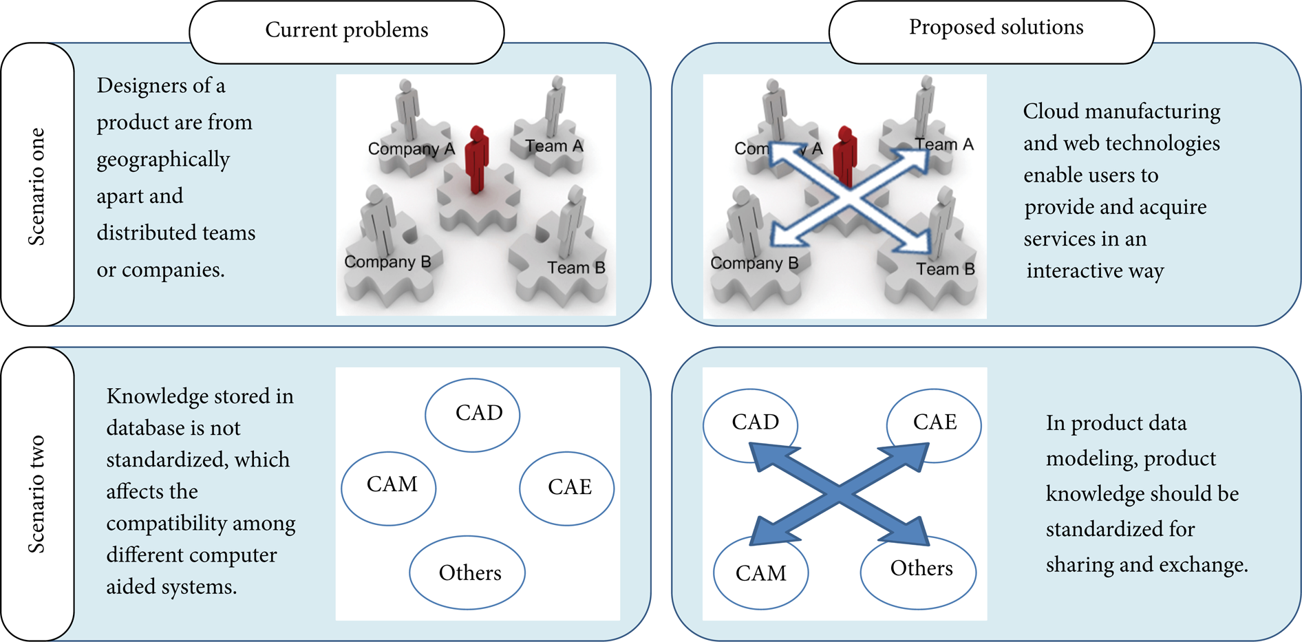
Current issues and solutions in OKP design [5].
Another DES issue in collaborative OKPPD is incompatible file formats in computer-aided designing and manufacturing systems. Consequently, it reduces the ability for PD collaboration as it would take more time transferring and interpreting data between different systems. For example, in the design modelling phase, there could be different CAD systems employed by companies and teams. These systems usually have their own data formats and do not have the ability to support online data exchange. This would lead to difficulties in DES between designers and also result in problems of data compatibility in the downstream phases such as process planning and manufacturing. This problem usually occurs when an engineer tries to integrate product design and manufacturing activities by sharing product data between CAx systems. In this situation, both R&D teams and company partners in collaboration are isolated and incapable of exchanging and sharing data efficiently. This issue needs to be investigated further by developing new standards, data exchange protocols, and interfaces for knowledge exchange and sharing between the different data formats of CAD, CAE, CAM, PDM/EDM, and other CAx systems.
The rest of this paper is organized as follows. Section 2 reviews previous works and research gaps towards product data modelling and DES enabling aspects. In Section 3, a four-step product knowledge modelling approach and a data model are proposed to complete the representation of OKP product data. Then, a data exchange and sharing framework is proposed to address the above issues in OKP collaborative design. Section 4 covers the implementations to validate the proposed modelling approach, data models, and DES framework. Conclusions and future works are given in Section 5.
2. Related Works
It has been a broadly accepted fact that product knowledge can assist OKP companies to increase profit and quality while reducing time spent on new product development, reduces the negative impact of the loss of expertise, and enables agile OKPPD [2, 6–9]. Therefore, a suitable product knowledge modelling approach is essential for the survival of OKP companies [10]. STandard for the Exchange of Product model data (STEP) is an international standard that provides an unambiguous representation and an exchange mechanism for computer-interpretable product information throughout the lifecycle of a product [11]. This section reviewed current studies on three research fields that can facilitate OKP data management and collaborative PD which are STEP-based product data modelling, cloud manufacturing, and DES approaches based on STEP.
2.1. STEP-Based Product Data Modelling
STEP-based knowledge modelling is a kind of object-oriented modelling approach, and thus it possesses the advantages of object-oriented modeling; that is, encapsulation of data and operations related to that data emphasis on reuse of modelling objects and an inheritance mechanism. As this approach can deal with uncertainties and complexity that happen in OKPPD, it is suitable for modelling OKP product knowledge [12].
Quite a few studies have been made of STEP-based product data and knowledge modelling in different PD stages, such as design, process planning, and assembly, based on STEP [9, 13–15]. For instance, Waiyagan and Bohez built up a STEP-based process planning knowledge-based system, which can be integrated with CAD tools [16]. Zha and Du (2002) proposed a PDES/STEP-based modelling approach for concurrent design and assembly planning. STEP-based modelling approaches can also be used supporting concurrent engineering activities [17, 18]. Concurrent engineering is easily found in OKPPD for shortening lead time and enabling PD efficiency [18]. Valente et al. developed a STEP compliant knowledge-based data structure to support manufacturing agility in a dynamic manufacturing environment for automated scheduling and manufacturing of products [19]. However, the majority are aimed at assisting only one or two activities in PD [2], which is not enough for OKPPD of complexity in a concurrent environment. Also, these systems are inadequate for integrating other development activities (e.g., process planning and customer interactions), which makes them less feasible for supporting OKPPD.
The integration of PD activities can greatly enhance the application range of systems. Xie and Chen developed a generic product modelling framework for rapid development of customised products based on STEP [11]. In this research, a product data model was built for product design, manufacturing, and assembly. However, it failed to include customer information and the activities involved in PD processes. An OKP company is required to cope with changing customer requirements and continuous impacts from customers accurately and carefully [20]. As such, this model is incomplete and inapplicable for OKPPD as they claimed.
From current studies on STEP-based data modelling, we can see that STEP-based approaches can deal with the uncertainties and complexity that occurs in OKPPD, and thus they are suitable for modelling OKP product knowledge [21]. There are, beside geometric product knowledge, many other kinds of product knowledge related to collaborative OKPPD activities (such as process planning, manufacturing, resource). However, STEP mainly models the geometric information of products, which leads to issues of incomplete data representation. It is necessary to build an integrated data model to fully represent product data in OKPPD activities.
2.2. Web Technology
Web technology is one of potential solutions to real-time information communication problems. In a customer-oriented PD environment, more efficient communication between companies and designers is of great importance. Web-based approaches have attracted more and more attention in recent years. Systems based on the Internet and WWW (World Wide Web) can enhance the interactive level between users and designers [22]. With the help of Web technologies, customers are allowed to be involved through the whole process of PD with R&D teams and make their own decisions on orders collaboratively. Web technologies provide a virtual path for data sharing and exchange [23]. Real-time data exchange allows communication and modifications instantly, with all users of the OKPKMS. It will reduce the possibility of reworking and realise a “once” success approach for OKPPD.
There is an emerging trend of decentralisation of design teams, functionally and geographically [13]. Through the Intranet and internet, geologically distributed engineering teams and partner companies can be connected for collaborative OKPPD. Web technologies make global collaboration possible. Therefore, a variety of WWW-based systems have been developed for the purpose of customised PD. For example, a Web-based integrated PD platform was developed by Xie et al. [24] for concurrent design and manufacturing customised products. Xu and Liu [22] proposed a Web-enabled product data management (PDM) system to enable a collaborative design environment.
Additionally, as the speed of searching and sharing product knowledge has accelerated, along with the increasing speed of the Internet and computers, a web-based product knowledge management system is more feasible for OKPPD, to ensure real-time and agile responses. For example, Qin et al. developed a web-based conceptual design system, by which product design can be evaluated and modified quickly over the Internet [25]. However, due to the various knowledge formalisms, reusing unstandardised knowledge from the web is still a large problem. This could be solved to some degree through integrating with STEP approaches that provide standardisation of product knowledge.
2.3. Two DES Scenarios in Cloud Manufacturing
Cloud manufacturing is a new manufacturing paradigm derived from the concept of cloud computing, which offers a range of manufacturing related services to its cloud users [26]. A manufacturing “Cloud” utilises these virtualised resources to provide on-demand and online services to its users (cloud users). Integrated with web technologies, cloud manufacturing provides a web-based platform for supporting collaborative PD. Therefore, it allows designers distributed geographically and organisationally to upload and request services according to their needs, regardless of time and location [26]. Models, data, information, knowledge, and tools are the typical manufacturing resources required in manufacturing clouds. The objective of cloud manufacturing is to offer secure and reliable services for supporting manufacturing activities. However, so far there are still limitations and gaps in achieving this objective, for example, secure DES between cloud users. In the rest of this section, two DES scenarios in cloud manufacturing are put forward, and limitations are identified.
The first scenario is the DES between users on the same manufacturing cloud. The cloud combines a range of product databases and manufacturing services. Cloud users can provide and acquire a variety of online data and services, for example, provide services, upload data files, request data/service, and exchange product data through web-based user interfaces. In this scenario, cloud services and data are provided and requested by cloud users on the same manufacturing cloud. As shown in Figure 2, “designer 1” uploads CAD product models to the manufacturing cloud, and then “designer 2” requests the data/services for real-time collaborative PD. Probably, “designer 2” may use these data and services to support different manufacturing activities, such as design review, cost estimation, and process planning. The quality of cloud services is determined by the compatibility and interoperability of cloud data. In the author's point of view, this depends on whether the data is in a standardised format or protocol.

Web-based DES for OKP collaborative design in cloud manufacturing.
Another scenario is a DES between users from different manufacturing clouds. Xu (2012) stated that “services and data with interoperability allow applications to be exchanged between clouds, or to use multiple cloud infrastructures before business applications are delivered from the cloud” [26]. As illustrated in Figure 3, more than one private cloud is usually involved in cloud manufacturing practice in this scenario. Within each cloud, data and services are shared and exchanged between its users as in the first scenario. Also, in the second scenario, security of data becomes an inevitable issue. In cloud manufacturing, information on clouds usually consists of a variety of intellectual company assets such as designs, customer information, and manufacturing information. Although companies need data exchange to support collaborative PD, they will not intend to share all of these with other companies.
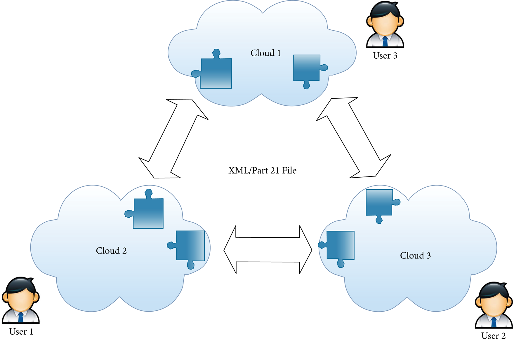
Data exchange between clouds.
Figure 3 illustrates an example of the second scenario. Suppose that there are three manufacturing clouds; without DES between them it is impossible for users from cloud 1 to acquire the data and services exclusively provided by cloud 2. Moreover, for security reasons, only information at certain levels, rather than any complete information, is shared and exchanged with certain partners (clouds). For example, Cloud 1 may share the information of one function or service with Cloud 2 and share the knowledge of another function or service with Cloud 3.
3. Methodologies
In this section, a four-step product modelling approach is proposed based on STEP according to the requirements of OKP collaborative design. EXPRESS-G product data schemas are also defined. In these schemas, entities defined in STEP standards and self-defined are integrated. Then, a DES framework is proposed to support both discussed DES scenarios in cloud manufacturing.
3.1. The STEP-Based Data Modelling Approach
A STEP-based data model proposed in this research consists of four submodels, and each submodel has several schemas to represent related information. This data model contains not only STEP-defined entities and schemas but also newly self-defined ones. The integration of the four submodels is of great importance for data model implementation. As such, the following four-step data modelling approach is proposed here.
Step1 (choose objects of OKP products and generate model structure). In the four submodels, the product model is a feature-based model that contains general product information, assembly information, part information, and so forth. It also provides references for process planning. The proposed data model takes customer involvement into consideration as it can help OKP companies develop highly customised products. The customer model was developed for modelling customer information, for example, general customer information, customer requirements, product feedbacks, and order information. The resource model covers information about resources used in OKP development, for instance, the human resource, machining resource, and machining tools. The manufacturing model stores information concerning manufacturing activities.
Step2 (check defined product information from STEP generic resource and APs). Each submodel in the proposed STEP-based data model consists of several entities and schemas according to the need to support OKPPD activities. Some standards and application protocols (APs) are already defined by STEP and can be used directly. For example, ISO 10303 AP203 defines entities and schemas for the product configuration controlled 3D designs of mechanical parts and assemblies. Table 1 shows a part of the selected entities and schemas from the integrated generic resource and APs.
Schemas and entities in the proposed data model (partial).

Step3 (define basic entities and schemas in submodels through EXPRESS language). As mentioned, not all these entities and schemas are already defined in a STEP data model. To complete the representation of the proposed model, some self-defined entities and schemas are defined and listed in Table 1. For example, as entities and schemas in the customer model are not included in any STEP AP, several self-defined schemas, for example, customer requirement schema, order schema, and feedback schema, were generated to complete the proposed data model. The selected STEP-defined entities and schemas and the self-defined entities and schemas were integrated to build the proposed product model.
Step4 (create the connections between entities). After completing all submodels, it is important to discover the connections between submodels and schemas. So the last step is to map entities from different submodels through discovering relationships between the entities. Figure 4 shows the EXPRESS-G diagramme of the whole product data model, and connections between four submodels. The entities of this diagramme are expandable according to different needs of OKP design. Entities and schemas in each submodel and their connections will be explained in detail in Section 3.2.

The EXPRESS model example and its corresponding EXPRESS-G schema.
In the proposed data modelling approach, the EXPRESS and EXPRESS-G languages (ISO 10303-11) are used to describe this data model by defining entities, types, constraints, functions, and rules of each schema. EXPRESS is a standard formal information modelling language in STEP. EXPRESS-G, the graphical expression of EXPRESS, supports a subset of the EXPRESS language for displaying entities and type definitions, relationships, and cardinality. On the left of Figure 4, an example is given to show how to represent entities and their relationships using EXPRESS. On the right are the corresponding EXPRESS-G schemas.
Both EXPRESS and EXPRESS-G represent STEP-based data models in a complete, precise, and unambiguous way. The following specified advantages of EXPRESS and EXPRESS-G were summarised in the literature [27, 28]:
normative description language based on an international standard,
human readable and computer interpretable,
object-oriented features are supported (e.g., single and multiple inheritances),
independence of physical data representation,
Expandable hierarchical structure.
3.2. The STEP-Based Data Model
The proposed STEP-based model consists of four submodels representing product data of different aspects: product, customer, resource, and manufacturing, respectively. With the proposed four-step data modelling approach, the STEP-defined entities and schemas are integrated with the self-defined ones to form the proposed product data model.
3.2.1. The Customer Model
Although customer involvement in OKPPD is of increasing significance, the representation of customer data has been ignored in many previous product models [15]. In the proposed data model, customer activities will be taken into consideration. The customer model consists of several EXPRESS schemas to allow modelling customer-related data in PD, for example, customer general information, customer requirements, and order feedbacks (Figure 5).
The customer information schema is defined to model general customer information (address, contacts, company name, and so forth). Some entities (entity “address”, entity “person”) in this schema can be found from STEP Application Protocol, AP203 (ISO 1994) [29] and Part 41. Detailed information is listed in Table 1.
Entity organisation is the root of the customer information schema, which has a series of entities and types to define and represent general customer information. This schema can help OKP companies manage their customers.
The order information schema is defined to represent information about customer orders. The root entity is entity order, which has order date information, order deadline information, order budget, order unique id, and description of order, and so forth.
Entity feedback records the feedback of each order, which contains customer feedback about their satisfaction with product quality, customer service, and a description of service limitations.
Entity customer requirement is a part of the order information schema. It is defined to represent CRs on each order. Entity customer requirement is used to store original CRs in text or document format, while entity parameterised requirement is used to represent engineering characteristics translated from original CRs.

EXPRESS-G diagramme of the customer model.
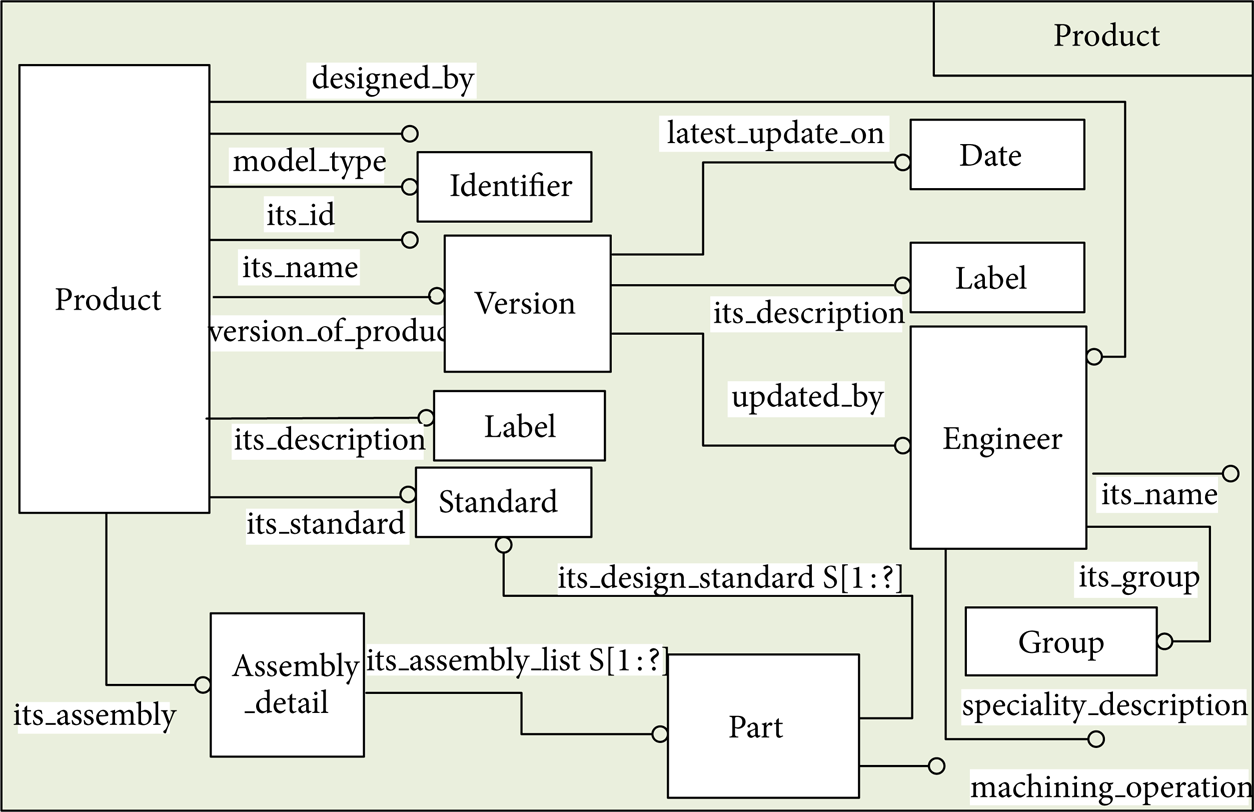
3.2.2. The Product Model
The product model is designed to define product general information, progress information, and assembly information. It consists of three schemas, which are the product general information schema, the assembly information schema, and the part schema (Figure 6).
The product general information schema is defined to represent product information containing several entities, for example, product version, engineers for product design, and standards for product.
Entity version records dates of the latest version of a product and the engineers who updated it. This entity can allow both customers and engineers to track progress. It is useful for dealing with dynamically changing CRs.
The assembly information schema is defined to represent the assembly information of each product. Part is the basic component of products, so that component information and their assembly methods are needed in PD.
The part schema is defined to represent information of part components in products. It is a feature-based structure as the features in each part will be recorded and sorted into product databases. In future, we could develop the same parts of new products by reusing feature information and adapting the parameters of features.
EXPRESS-G diagramme of the product model.
3.2.3. The Manufacturing Model
The manufacturing model contains two schemas: the process planning schema and the machining schema (Figure 7).
The process planning schema represents the actions of machining parts. Entity action, a subtype of entity action assignment, represents action method, action id, and action description. The sequence of actions is defined in entity action relationship by giving out the relating action and related action.
The machining schema shows the machining operations of parts. This schema is connected to the part schema defined in the product model. It represents machining technologies, and machining functions. Entity machining functions is connected to the machining resource schema in the resource model.

EXPRESS-G diagramme of the manufacturing model.
3.2.4. The Resource Model
The resource model contains three kinds of resource in companies, which are human resource, machining resource, and supplier resource. This model can help OKP companies manage their employees, shop floors, and manufacturing scheduling (Figure 8).
The human resource schema is defined to represent the information of employees and their occupation roles. Besides being basic human resource information, this schema is mainly designed to record engineer activities when developing previous products.
Entity engineer is a subtype of entity human resource, as engineers are employees. Through keeping their records, engineer expertise can be identified and tracked. Based on this, companies can assign work to the corresponding engineers and teams who have experience on products of a similar kind efficiently, to achieve greater PD effectiveness.
The machining resource schema is defined to model machining resource information which contains machine information, machining tools information, and material for machining information.
Entity material represents material type, unit cost of material, and supplier. The entity supplier is defined to model supplier information. It will help companies arrange the manufacturing processes of a customised product. For instance, wood is needed to produce the body of doors, so this part cannot be manufactured and the process of manufacturing cannot be arranged before wood is supplied.

EXPRESS-G diagramme of the resource model.
3.2.5. The Integrated Model
Each kind of product is developed according to orders placed by individual customers, which is the connection between entity product and entity order. CRs and parameters from the order schema are important references of PD. Also, entity version can represent the progress of PD, so that customers can track their order progress easily. Entity part in the product model and entity machining operation from the manufacturing model are connected, as machining operation is determined by different features of each part (as shown in Figure 9).
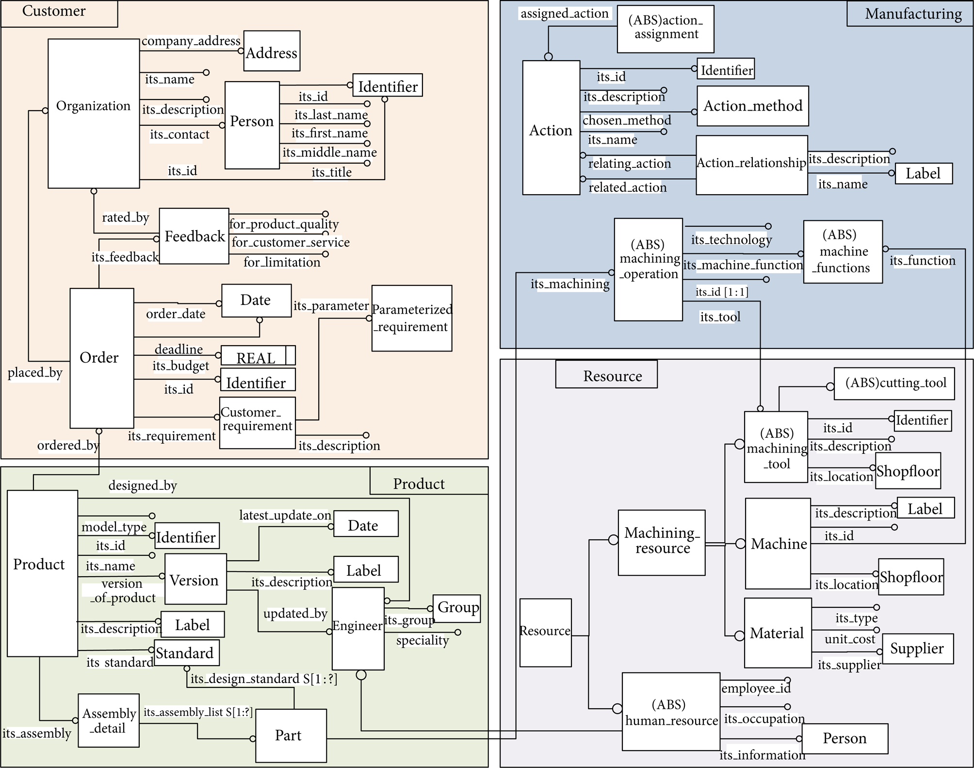
EXPRESS-G diagramme of the integrated data model.
Entity machining tool in the resource model represents the machine tools information needed in machining operations. Machining function is a unique definition of machining tools and machines, for example, a cutter is used in the cutting process, while a milling cutter is for milling machining. As such, entity machining functions is connected with entity machining tool and entity machine from the machining resource schema.
An engineer is a company employee, so entity engineer is connected to the human resource schema. In the resource model, human resource schema is defined to model the general information of employees, which includes their ID, occupation, and person information (name, address, email, telephone number, etc.). In the product model, engineers are designers of products. Each can be an update of the product version, has their own specialty, and belongs to a group for developing products. All these relationships are shown in the product model.
3.3. Framework for Data Sharing and Exchange
To deal with DES scenarios in cloud manufacturing (discussed in Section 2.3), in this research a DES framework was proposed, based on the proposed STEP-based product data model. According to [30], there are usually two ways to enable DES in cloud manufacturing scenarios. The first way uses STEP exchange files (also known as Part21 files), which is mainly used for the DES of product geometric data. Therefore, it can assist DES between CAx systems, like CAD model review between different CAD systems. Another way is via a shared database access, using a standard data access interface (SDAI). This is mainly adopted to enable the DES of other design-related applications. The proposed framework utilises both of them to facilitate DES in cloud manufacturing. The predefined STEP data schema plays an important role in this scenario. By using the same STEP data schema, that is, the same standardized data structure and method, DES between two clouds can be realized. In this case, data incompatibility or data conversion can be avoided, so that unnecessary cost can remain as minimum, and the interoperability can be guaranteed.
Figure 10 shows the DES framework, which enables not only a DES between cloud users from the same manufacturing cloud, but also a DES between different manufacturing clouds. The process in the grey block is for enabling DES between users from different manufacturing clouds. By using the “EXPRESS Compiler” tool provided by ST-developer, the corresponding ROSE library and C++ classes are generated from the EXPRESS-G schema developed in Section 3.2. According to [31], ROSE applications can interpret and obtain product information in Part21 files.
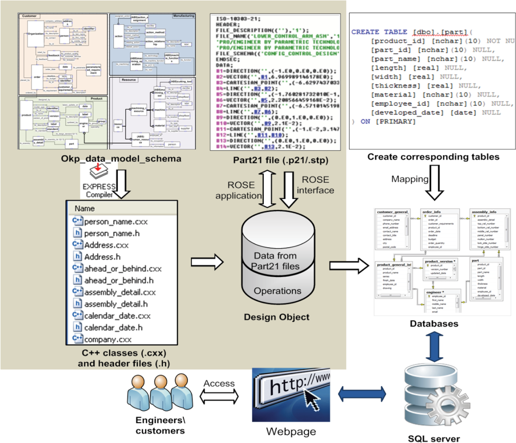
The proposed DES framework.
The EXPRESS-G schemas are transformed to relational databases for the following reasons. Firstly, data schema is just a structure of data storage that cannot be stored by databases, so it should be translated and transformed to data dictionary [32]. Secondly, product information stored in databases can be transplanted to other systems that also employ this technique. As a mature technique, databases are widely employed in manufacturing systems. Last but not least, data represented in Part21 files cannot be interpreted and accessed directly from web-based user interfaces. Therefore, product databases corresponding to EXPRESS-G data schema should be built for data storage, management, and analysis on manufacturing clouds.
These databases are empty before being filled with data, so product data should be input and allocated into corresponding databases. Data for constructing product databases can be obtained by extracting it from STEP files (also known as Part21 files) or accessing the internet to input data online manually. The generated ROSE library and C++ classes extract and operate product data from STEP files. The ROSE application maintains all the methods dealing with the extracted data. By putting the extracted data into design objects, data can be filled into corresponding tables in databases. Data in the databases is accessible directly via web-based user interfaces.
In this framework, DES can be either file based or Internet based. The file-based approach writes the data into a *.stp file using a STEP file parser and sends the file to other clouds for sharing or saves the file into storage for archiving or backup. Because all the information is standardised using STEP-based schemas, the saved Part21 file will never be obsolete and will be compatible with a system with a newer version. By using an Internet-based method, the data is saved in flowing XML format, which is suitable for transmission through the Internet. The exchange can be processed automatically, frequently, and synchronously. Each cloud can decide to exchange the whole or part of the data with a certain partner. Because the data is organised by entities, whether the data is whole or partial will not affect the efficiency of the exchange. Therefore, it enhances the interoperability and compatibility of data and thus enables DES between different CAx systems. Hence, it is essential for the integration of PD stages and collaboration with distributed engineering teams.
4. Case Studies
In this section, two case studies were carried out to illustrate the advantages of the proposed DES framework in collaborative OKPPD. The first case study shows how the proposed EXPRESS-G data schemas support the downstream applications (cost estimation) in PD. The second case study demonstrates the DES between clouds.
In these case studies, ST-Developer and Visual Studio C++ were used as the tool for defining and developing the product data models, and a SQL Server 2008 was employed to provide management of the databases, such as data storage, retrieval, and analysis. Microsoft Visual Web Developer was employed to develop web pages for the interface layer and access to SQL databases through SQL queries.
4.1. Construction of SQL Databases
There are three steps to translate the EXPRESS schema into relational databases: (1) creating corresponding tables; (2) mapping tables by relationships and rules; (3) inputting data into tables. A SQL database is a relational database, which is comprised of many related tables. Tables are the basic structure of a relational database. Therefore, the first step is to create corresponding tables. Entity, the basic cell in the EXPRESS data schema, corresponds to a table in SQL databases. Figure 11 shows the relationships between entities of EXPRESS-G schemas and table creation commands in the SQL method. In both EXPRESS and SQL, each attribute/column has its own data type. The data types and attributes are set up by following the rules for translation from EXPRESS entities to SQL tables [33]. Taking ENTITY PART as an example, this is a child node of ENTITY PRODUCT. To get connection with PRODUCT, the product id is set as the primary key of the table part. That is, the reason that only product id is set as NOT NULL in SQL commands, as a primary key of this table indicates that this parameter is unique in all table columns.

The relationships between entities and SQL commands.
After the creation of Tables, the relationships between tables are defined. Through setting primary keys and foreign keys to each table, we can represent not only the “one to one” relationship but also “one to many” and “many to many” relationships. A primary key is used to uniquely identify each row in a table. For instance, as “engineer” is a kind of employee in a company, each engineer, obviously, has a unique employee ID. Therefore, we set employee id as the primary key of the engineer table. Before filling product data into these relational tables, the databases are empty. The two ways of obtaining and filling product data into the databases were discussed in Section 3.3.
4.2. DES for Supporting Cost Estimation
Nowadays, the mainstream 3D modelling software tools, Pro/E, SolidWorks, UG, and so forth, allow the user to transfer 3D models into an exchangeable file format (.stp). In STEP, AP203 was developed to represent the geometric data of models. As such, the geometric information of this design/model is compatible between different modelling tools. For instance, a model created by SolidWorks can be opened and reviewed by Pro/E after being saved as an exchangeable file format. For collaborative OKPPD, DES only on geometric data is obviously insufficient, as many other applications, such as cost estimation and process planning, are needed. With the proposed data schema and entities, besides the geometric information of this model, data of other types are stored in corresponding databases on a cloud to facilitate different applications in PD.
Cost estimation of this design is taken as an example here. The cost estimation service helps engineers estimate part cost at the design stage. The following equation explains the total cost of manufacturing this part. In this case, the total cost includes the cost of material, the cost of machining, and the cost of paid workers:
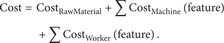
The cost of material is determined by material type and part dimensions, which are defined by designers. The cost of machining relies on the time spent on machining each feature and the machining types. For example, this part contains one keyway, which needs to be machined on a milling machine, while the three drilled holes should be machined on a drilling machine with three cutters, according to the different diameters of holes:

In (2), CostUnit denotes the unit cost of a specific machine, including the unit tool wear and machine wear during manufacturing a feature. TimeMachining(feature) stands for the time spent on machining the specific feature. Therefore, the cost of machining each feature equals their multiple:
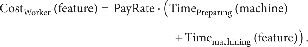
For each feature, the cost of a paid worker depends on the time of preparing and machining this feature and the pay rates of workers as shown in (3). The time spent on changing cutters and clamping machining parts is normally longer than machining, which should be taken into consideration. TimePreparing(machine) indicates the preparation time before machining the specified feature. It is more efficient to machine features of the same type together than separately. All the required information can be acquired from databases on the manufacturing cloud. As such, the total cost can be estimated by using (1), (2), and (3).
The 3D CAD model of the shaft part shown in Figure 12 was designed and structured with SolidWorks 2012. Besides its geometric data, other related data, for instance, machining features, dimensions, and material information, is stored on the manufacturing cloud. Serviced by the same cloud, other designers can acquire the exchange file of this model for design review, and also its related data for cost estimation.

Cloud data for different applications.
Table 2 shows the schema and entities defining the required data for cost estimation. For example, the machining operation schema can provide data for TimePreparing(machine), as this schema describes machining operations such as milling machines for keyways. The preparation time before this machining operation includes the removal time, the clamping time, and the cutter setup time, which are all defined in the proposed schemas. Through mapping to the relational databases (SQL databases), these schemas are translated to the corresponding tables and databases. Cloud users can acquire data they need from manufacturing cloud via web-based user interfaces at anytime and anywhere.
The required data for cost estimation.

4.3. DES between Clouds
An EXPRESS information model contains data structure definitions, along with matching rules and constraints. After defining these schemas of each submodel by using EXPRESS modelling language, ST-Developer v12, in this research, has been used to compile the proposed model with the “EXPRESS Complier” tool. This tool parses and checks information models defined in the EXPRESS language. Figure 13 shows that this EXPRESS data schema okp data model schema has parsed an EXPRESS compiler. This compiler also produces [34]:
a data dictionary, in the ROSE data format, that application programs use to read and write STEP Part 21 files. These files are named after the schemas as
EXPRESS parse information for the SDAI EXPRESS interpreter and AP conformance checking tool. These files are in the ROSE format and are named after the schema with the EXPX extension, as
ST-Developer ROSE applications create a data set based on the EXPRESS schema in the application working space. The RoseDesign object manages the data sets by maintaining the data objects and the operation processing them. The ROSE interface object, which is an instance of RoseInterface objects, defines the operation of the entire application working space, taking charge of the reading, writing, creating, and managing designs. There can be many design objects corresponding to different sets of information the user wants to share with the partners. The design object containing partial information can easily synchronise with the design object containing complete information within the working space. After assigning the current design to the ROSE interface object, the design object can read and write STEP files in Part21, Part28, and binary ROSE working form.

Schema parsed EXPRESS compiler.
Here is an example. For a partial data exchange, a new design object is generated by

This will create an empty new design, and the design will be saved into partial.stp in the future. After deciding the data to be exchanged, the cloud sets the corresponding entities from the data base. The following code is used to save the design into the partial.stp file:

When it receives the file partial.stp, the other cloud can read the information from the file into the design by

The data format of the saved file can be set by

From the case studies, the following conclusions can be drawn. The proposed DES framework and STEP-based data modelling approach can enable DES in cloud manufacturing for an OKP collaborative design. Cloud data represented by the EXPRESS-G product schemas can support collaborations among OKPPD activities. By addressing issues in OKP collaborative design, the DES module has certain advantages. Firstly, the STEP-based data modelling approach addresses the issues in many modelling approaches on DES between different systems. It enables future integration between systems. Cloud databases provide related data to cloud users for other applications in the product design stage. Based on cloud manufacturing and web-technology, data acquiring is realised regardless of time and location. This enhances the quality of collaboration between distributed designers and companies.
5. Conclusion
In this paper, a STEP-based data model, a four-step data modelling approach, and a DES framework were proposed and developed for enabling DES in web-based collaborative OKPPD. The proposed STEP-based data model covers the four categories of product knowledge, which are customer, product, manufacturing, and resource. A few entities and schemas were defined for the first time, which fills a gap in the definition of STEP standards and protocols [15]. Compared with product models in the literature [11, 24, 35], this model represents more complete OKP product data, and thus it is able to provide adequate knowledge for the development of new OKP products. Based on the proposed data model, the DES framework was proposed and developed, which enables real-time DES in the web-based collaborative OKPPD. So far, to the author's best knowledge, no attempt has been done to enable DES in cloud manufacturing to support collaborative OKPPD activities. The proposed DES framework fills this research gap, for which two DES scenarios in cloud manufacturing are dealt with. Case studies were carried out to demonstrate the feasibility of the proposed DES module in OKPKMS. The case studies revealed that the completeness, interoperability, and compatibility of product data are enhanced greatly by the proposed STEP-based data model, the modelling approach, and the DES framework.
Conflict of Interests
B. M. Li declares no conflict of interest. S. Q. Xie declares no conflict of interest. Z. Q. Sang declares no conflict of interest. The support of the International Investment Opportunities Fund (IIOF) from the Foundation for Research, Science and Technology (FRST) of New Zealand (Contract number: UOAX0723) has no conflict of interest.
Footnotes
Acknowledgments
This paper is an extended version of the conference paper titled “A STEP-based product knowledge model for One-of-a-Kind Production” for The 2012 IEEE International Conference on Industrial Engineering and Engineering Management (IEEM 2012). The authors would like to acknowledge the support of the International Investment Opportunities Fund (IIOF) from the Foundation for Research, Science and Technology (FRST) of New Zealand (Contract number: UOAX0723).