
Abstract
Experimental data of heat transfer coefficient during evaporation of R-1234yf, R-134a, and R-22 in horizontal circular small tubes are compared. The local heat transfer coefficient is obtained for heat fluxes ranging from 10 to 35 kW m−2, mass fluxes ranging from 100 to 650 kg m−2 s−1, saturation temperatures of 5, 10, and 15°C, and quality up to 1.0. The test sections are made of stainless steel tubes with inner diameters of 1.5 and 3.0 mm, the lengths of 1000 and 2000. Effects of heat flux, inner tube diameter, and saturation temperature on heat transfer coefficient are reported in the present study. Nucleate boiling heat transfer contribution is predominant, especially at low quality region, and laminar flow appears in the evaporative small tubes. The experimental results are compared against four existing heat transfer coefficients, and the modified correlation of heat transfer coefficient is developed with good prediction.
1. Introduction
Environmental protection is one of the most important reasons that make human develop the sustainable technologies. In the refrigeration and air-conditioning fields, besides studying the renewable and saving energy systems, developing the environmentally friendly refrigerants is a grand mission. The roadmap of phasing out HCFCs such as R-22 has been outlined under the Montreal Protocol. Controlling the greenhouse gases was proposed through the Kyoto Protocol (1997). Recently, EU regulation [1] banned the refrigerants having global warming potential (GWP) greater than 150 in new mobile air conditioners (MACs) from 2011 and all models from 2017 in the EU market. R-134a that was widely used before the need to be replaced due to its GWP is equal 1430. Review by Calm [2] showed that refrigerants are going to the fourth generation in the demands of zero/low Ozone depletion potential (ODP), low GWP, short atmospheric lifetime, and high efficiency. Natural refrigerants such as CO2, NH3 are considered to be the promising candidates. The other one, R-1234yf developed by Honeywell and DuPont is also paid a considerable attention. The thermodynamic properties of R-1234yf are similar to the ones of R-134a, while its GWP is only 4. Hence, it meets the standard of EU regulation as well as the fact that the manufacture can minimize the change of equipment when replacing R-134a by R-1234yf.
To date, numerous studies about the heat transfer characteristics and performance of R-1234yf have been published. Park and Jung [3] investigated the nucleate boiling heat transfer coefficients (HTCs) of R-134a and R-1234yf on a plat plain and low fin surfaces. The experimental data were measured at the liquid pool temperature of 7°C and the heat fluxes from 10 kW m−2 to 200 kW m−2. The test results showed that the nucleate boiling HTCs of R-1234yf were similar those of R-134a. Saitoh et al. [4] performed the boiling heat transfer coefficient of R-1234yf inside a smooth small horizontal tube of 2.0 mm internal diameter. The data were measured at the heat fluxes of 6–24 kW m−2, mass fluxes of 100–400 kg m−2 s−1, an evaporating of 288.15 K and the inlet vapor quality of 0–0.25. He reasoned that the effect of heat flux on the heat transfer coefficient was large at low vapor quality, while the outcome of mass flux was large at higher vapor quality. The heat transfer coefficient of R-1234yf was almost the same as that of R-134a. He also compared the experimental HTCs with his correlation proposed in previous study, and the predicted results agreed well with the experimental ones. Lee and Jung [5] reviewed the performance of R-134a and R-1234yf in a bench tester for automobile applications. His experimental results showed that the coefficient of performance and capacity of R-1234yf are up to 2.7% and 40% lower than those of R-134a, respectively. The compressor discharge temperature and amount of charge of R-1234yf are 6.5°C and 10% lower than those of R-134a. He concluded that R-1234yf can be used as a long-term environmentally friendly solution in MACs. del Col et al. [6] reported the flow boiling of R-1234yf in a 1 mm diameter channel. This study showed that HTCs of R-1234yf is highly dependent on the heat flux while the mass velocity have no effect. With regard to the vapor quality, the HTCs decreased with the vapor quality up to 0.3, then it remained pretty constant. However, the published data in open library are still limited.
The aim of this study is to determine the HTCs during evaporation of R-1234yf in horizontal circular small tubes. R-22 and R-134a, although, will be phased out in the near future, but they are still being applied in many applications nowadays, especially in developing countries. Hence, this study also discussed their HTCs based on our previous experimental data. In addition, due to the limited of heat transfer coefficient correlation for R-1234yf in minichannel have been proposed, the modified correlations are developed with the good accuracy that can be improved the calculation on designing the compact heat exchangers using this new refrigerant.
2. Experimental Apparatus and Method
2.1. Experimental Test Facility
The experimental apparatus was comprised of a refrigerant loop, three water loops, and a data acquisition system. Figure 1 shows a schematic diagram of the refrigerant loop. The refrigerant flow system consists of a condensing unit, receiver, refrigerant pump, mass flow meter, and preheater. Vapor phase refrigerant from the evaporative test section was condensed into the liquid phase in the condensing unit. The condensed refrigerant was then supplied to the receiver. The refrigerant was pumped by the refrigerant pump, which is connected to an electric motor controller used to control the flow rate of the refrigerant. The Coriolis-type mass flow meter was used to measure the refrigerant flow rate. The vapor quality at the inlet of the test section was controlled using a preheater. Temperatures of condenser, sub-cooler, and preheater were adjusted by three individual water loops.

Experimental test facility.
2.2. Test Section
The test sections were made of circular stainless steel smooth tubes with inner diameters of 1.5 and 3.0 mm. The heated lengths were 1000 and 2000 mm in the horizontal orientation. For evaporation, power was conducted from an electric transformer to the test section. The input electric voltage and current could be adjusted to control the input power. The test sections were well insulated with rubber and foam. The outside tube wall temperatures at the top, middle, and bottom sides were measured at every 100 mm axial intervals of the heated length using T-type thermocouples. The local saturation pressure, which was used to determine the saturation temperature, was measured using Bourdon tube-type pressure gauges at the inlet and the outlet of the test section. A pressure transducer was also installed to measure the pressure drop gradient of the refrigerant between the inlet and outlet of the test section. Sight glasses, having the same inner diameter as the test section and a length of 200 mm, were installed to visualize the flow and to enhance the flow stability of the fluid when entering the test section.
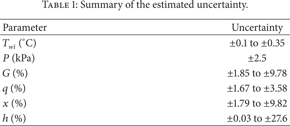
The physical properties of the refrigerant were obtained from REFPROP 8 [11]. The temperature and flow rate data were recorded using data acquisition and flow meter, respectively. Table 1 gives a summary of the estimated uncertainty associated with all the parameters at a 95% confidence interval. The uncertainties, obtained using the RSS method [12], included both random and systematic errors, and these changed values according to the flow conditions, so their minimum to maximum ranges were shown. The experimental conditions were also shown in Table 2.
Summary of the estimated uncertainty.
Experimental conditions.

2.3. Data Reduction
The local physical properties of the refrigerant were determined from the measured saturation pressure at the inlet and outlet of the test section. The mass quality x along the test section was evaluated based on the local thermodynamic properties

where i is the enthalpy [kJ kg−1], f is the saturated liquid condition, and g is the saturated vapor condition. The local heat transfer coefficient h along the length of the test section is defined as follows:
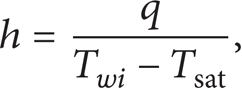
where q is the heat flux [kW/m2], T is the temperature [K], w is a tube wall of the test section, i is the inner side, and sat is the saturation condition. The inside tube wall temperature T wi is the average temperature of the top and bottom wall temperatures, and is determined using steady-state one-dimensional radial conduction heat transfer through the test section wall. The saturation temperature T sat was obtained from the measured saturation pressure P sat .
3. Result and Discussion
3.1. Heat Transfer Coefficient
3.1.1. Effect of Heat Flux
Figure 2 shows that the dependence of the HTCs on heat flux appeared in the low quality region for R-1234yf and R-134a. The mass flux and saturation temp. were kept constant at 500 kg m−2 s−1 and 10°C, respectively. The trend depicts that in the low quality region (vapor quality < 0.3), the HTCs increased with increasing heat flux. It means that the nucleate boiling heat transfer mechanism is dominant in the initial stage of evaporation and it was suppressed when the vapor quality increases. The result was in good agreement with the other one, represented in the study on HTCs of R-1234yf by Saitoh et al. [4].
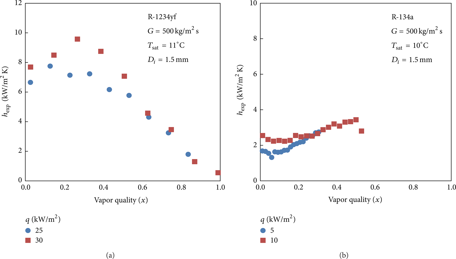
Effect of heat flux on heat transfer coefficient for R-1234yf and R-134a.
3.1.2. Effect of Inner Diameter
Figure 3 illustrates the effect of the inner tube diameter on the heat transfer coefficient. In the low quality region (x < 0.2), a smaller inner tube diameter shows a higher heat transfer coefficient. This is due to more active nucleate boiling in the smaller diameter tube. As the tube diameter decreases, the contact surface area for heat transfer increases. More active nucleate boiling causes dry patches to appear earlier.

Effect of inner diameter on heat transfer coefficient for R-1234yf and R-22, respectively.
3.1.3. Effect of Saturate Temperature
The effect of saturation temperature is shown in Figure 4. The HTCs increased with increasing saturation temperature, which was due to more active nucleate boiling as shown by our experimental data. These results can also be explained by considering the physical properties of the fluid such as pressure, density ratio ρ f /ρ g , viscosity ratio μ f /μ g , and surface tension.
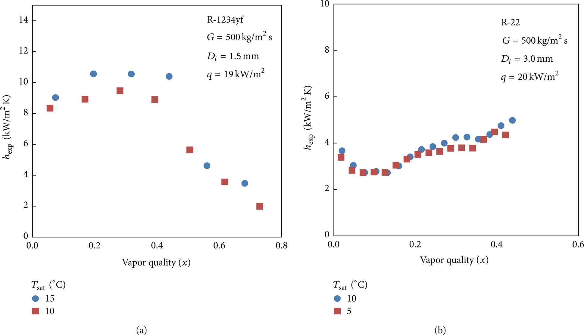
Effect of saturation temperature on heat transfer coefficient for R-1234yf and R-22.
3.1.4. Comparison between the Experimental and Predicted Value of Some Correlation
The HTCs of R-1234yf in this study were analyzed and compared using some heat transfer coefficient correlations. Figure 5 shows comparisons of the experimental heat transfer coefficient with Gungor-Winterton [7], Shah [8], Wattelet et al. [9], and Tran et al. [10]. Among them, Gungor-Winterton correlation gave the best results.
Comparison of heat transfer coefficient between the experimental data and the prediction with existing correlations.
3.2. Development of New Heat Transfer Correlation
Various studies [13, 14] showed that the heat transfer coefficient correlation for conventional tube could not predict well the heat transfer coefficient of minichannel. In addition, Bertsch et al. [15] reviewed several heat transfer correlations for minichannels and microchannels. The study noted that most of them developed based on small testing conditions and, consequently, these correlations did not extrapolate well beyond their often narrow operating range. Therefore, in the present work, the modified heat transfer coefficient correlations were developed using our data. The formula was based on the Chen correlation [16] that used the physical superposition approach.
3.2.1. Modification of Factor F
The flow boiling heat transfer in a tube, following Zhang et al. correlation [17], mainly consist two mechanisms: nucleate boiling and forced convective evaporation. A superposition model of the heat transfer coefficient may be written as follows:

The factor F is introduced as a convective two-phase multiplier to account for enhanced convection due to cocurrent flow of liquid and vapor by Chen, where F = fn(X
tt
). Since the effect of small tube that make the convective heat transfer for evaporating refrigerant in small tube delayed with that in conventional tubes, the function should be physically evaluated again. Chisholm [18] introduced a relationship between the factor F and the two-phase frictional multiplier that is based on the pressure gradient for liquid alone flow,

For liquid-vapor flow conditions of turbulent-turbulent (tt), laminar-turbulent (vt), turbulent-laminar (tv), and laminar-laminar (vv), the values of the Chisholm parameter C are 20, 12, 10, and 5, respectively [16]. The Lockhart-Martinelli parameter, X, is defined as follows:

where ((dp/dz)F) is the pressure gradient due to friction (N m−2 m−1) and ρ is the density (kg m−3). The friction factor f in (5) was obtained by considering the flow conditions of laminar-turbulent flows where f = 16Re−1 for Re < 2300 (laminar flow) and f = 0.079Re−0.25 for Re > 3000 (turbulent flow). The liquid heat transfer coefficient is defined by the Dittus-Boelter correlation [19]:

The F factor proposed by Zhang et al. [17] did not cover all the operating conditions in this work. Hence, a new factor F was developed from our experimental data using the regression method. Note that, the minimum value of enhancement factor equals to 1 for pure liquid or pure vapor. Hence, its formula was proposed as

The a1, b1, and c1 coefficients in (7) were listed in Table 3.
Coefficients for the convective two-phase multiply factor F.

3.2.2. Nucleate Boiling Contribution
The nucleate boiling heat transfer of the experimental data was predicted using the Cooper correlation [20]. For a surface roughness of 1.0 μm, the correlation is given as follows:

The nucleate boiling suppression factor S in our correlation is function of boiling number Bo and two-phase frictional multiplier ϕ f 2. Using the experimental data from this study, a new nucleate boiling suppression factor, a ratio of hnbc/hpb, is proposed as follows:
The coefficients of (9) for each correlation are illustrated in Table 4. A modified heat transfer coefficient correlation was developed by the regression method with 1175 experimental data points. The whole comparison of heat transfer coefficient between the experimental data and prediction using our correlation is shown in Figure 6. The proposed correlation provided very good prediction with the overall mean deviation for three refrigerants of 13.39%. The deviation for each correlation is tabulated in Table 5.
Coefficients for the nucleate boiling factor S.

Deviation of the heat transfer coefficient comparison between the present data and the prediction using the new developed heat transfer coefficient correlations.

Comparison of heat transfer coefficient between the present experimental data and predicted values using newly-modified correlation.
4. Conclusions
The convective boiling heat transfer coefficients were experimentally performed in horizontal small tubes with R-1234yf, R-134a, and R-22. The effects of heat flux, inner tube diameters, and saturation temperatures at three states of 5, 10, and 15°C on heat transfer coefficient were discussed in this study. The experimental results illustrated that the HTCs increased with increasing heat flux because nucleate boiling is dominant much more strongly in low-quality region. The HTCs also increase with increasing saturation temperature and decreasing inner tube diameter. The experimental data of R-1234yf were compared using some existing heat transfer coefficient correlations. Among them, Gungor-Winterton [7] correlation gave the best prediction with the MD of 22.5%. Other correlations were underpredicted. Finally, the modify heat transfer coefficient correlations were developed based on the superposition model of the contribution of nucleate and boiling heat transfer with a good accuracy that can be applied to improve the compact heat exchanger design.
Footnotes
Nomenclature
Acknowledgments
This work was supported by the Korea Institute of Energy Technology Evaluation and Planning (KETEP) Grant no. (2011T100100464) ofthe Energy Technology Development.