
Abstract
The turbine blade works at high thermal loads, especially the trailing edge of the blade due to the hot gas leakage flow. Pin-fins are well recognized as a kind of effective device to augment the convective heat transfer and effectively cool the trailing edge. In this paper, the cooling effectiveness of chordwise outlet pin-fins distance and inner pin fin diameter is, respectively, studied on the heat transfer and flow friction of the trailing edge of the blade with software CFX. A 90 deg turn cooling wedge passage with cylindrical pin-fins is used to model the trailing edge. Results show that the pin-fins distance at the outlet and the arithmetic arrangement of the inner pin-fins diameter both are vital factors to influence the cooling effectiveness in the trailing edge of the blade.
1. Introduction
It is well known that the thermodynamic efficiency of the gas turbines can be highly increased by raising the inlet working temperature, and therefore the highly effective cooling system of turbine blades is indispensable. The trailing edge of the blades has very thin cross-section which makes it very feeble to high temperatures and brings about a particular challenge to cool it. Pin-fin arrays are introduced as appropriate cooling devices to lower down its temperature. Pin-fins increase the internal cooled surface area and produce a high turbulence level to enhance the convective heat transfer performance between the cooling gas and the inner wall of the blade. They can also strengthen the intensity and stiffness of the trailing edge structure.
Lots of work has been performed on the heat transfer and flow characteristics of rectangle channels with the pin-fins. The influence of pin-fin cross-section shapes has been experimentally studied on rectangle channel with elliptic shape by Li et al. [1], with square shape by, respectively, Şara [2] and Jeng and Tzeng [3]. Sahiti et al. [4] numerically simulate the pressure drop and heat transfer of rectangle channels with a NACA profile, a profile having a drop shape, a lancet profile, an elliptic profile cross-section pin-fins. Among all the cross-section shapes, the circular one is the most popular [5–7]. Chang et al. [8] experimentally studied the endwall heat transfer distribution and pressure drop for four rectangular channels with different ratios between clearances from pin tips to the measured endwall and the pin-fin diameter. They found that the area average endwall Nusselt number and the pressure drops both decrease with the increasing ratios. Yu et al. [9] performed experiments on rectangular duct with staggered arrays of pin-fins and found great improvement of an overall thermal performance of their geometrical configuration. The experiments of Lawson et al. [10] on rectangular duct found that spanwise pin spacing affects the pressure loss more greatly than streamwise spacing while the latter had a larger influence on the heat transfer than the former.
The real shape of the trailing edge of the gas-turbine blade is similar to the wedge duct. Hwang and Lui [11] conducted experiments on the heat transfer and pressure drop in the wedge duct pin-fin with the consideration of influence of Reynolds number, outlet flow orientation, and pin configuration. Bianchini et al. [7] investigated the numerical and experimental results of the wedge duct similar to the real trailing of the blade, and two pin-fin arrangements were taken into account as staggered arrays and pentagonal displacements.
In this paper, the connective heat transfer and flow friction of the stagger-arrayed circular pin-fins in the trapezoidal duct are numerically studied. The innovation of the paper is to design new structural styles of pin-fins in the trailing edge of the blade, and then we investigated the influence of the arrangement of distance between each two pin-fins at the chordwise outlet and the arithmetic arrangement of the pin-fins diameter in the inner duct on the cooling effectiveness. This study intends to give instructions on the design of cooling in trailing edge of the turbine blade.
2. Numerical Method
2.1. Geometry
A schematic drawing of a real blade is shown in Figure 1. The trailing edge of the blade is the wedge-shaped gas cooling passage, in which the gas flows from the blade root to the tine, for example, radial direction. The gas flows out from the chordwise outlet. A stagger-arrayed circular pin-fin arranged in the wedged duct is used to model the trailing edge of the turbine blade as shown in Figure 2. Two sets of solid faces, namely, Wall 1 and Wall 2, are indicated in Figure 3 for the use of boundary conditions. Wall 1 includes the top endwall, bottom endwall, and the side face, while Wall 2 is a set of the other outer faces without any inner faces in solid (shown in Figure 2). The cross-section in the cooling passage is given in Figure 3 where the pin-fins in the cooling passage are arranged in nine equidistant and staggered arrays with 13 pin-fins for each array in 2D. Totally, 117 pins span the distance between two principal duct walls. The dimensions of the bottom endwall and the top endwall are 15.5 mm × 30.5 mm and 15.584 mm × 30.5 mm, respectively. The thickness of the walls is 0.5 mm. All pin-fins stand vertically on the bottom endwall. The heights of the duct entrance and straight exit are 3.586 and 2 mm, respectively, forming a wedge angle of about 5.863°. The pin spacings in the same row along the radial (longitude) and chordwise (transverse) directions are 3 mm and 2 mm, respectively, while those in the adjacent row are 1.5 mm and 1 mm, respectively, as shown in Figure 3. Two cases are considered with variable distance between the pins at the chordwise outlet (Case 1) and variable diameter of pin-fins (Case 2), respectively (Figure 3).

The gas passage in the real cooling blade.
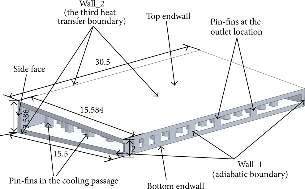
The detailed dimension of wedge-shaped duct.

The two-dimensional arrangement chart of the inner pin-fins in the near midplane of the cooling duct with radial inlet and chordwise outlet.
In Case 1, the diameter of all the pin-fins is the same value of 1 mm. There are 8 pin-fins with semicircular shape at the whole chordwise outlet location; therefore, these pin-fins partition the outlet to 9 portions denoted by X1 to X9. The dimension of the 9 portions is geometric-proportioned, and the proportion is set as a parameter η:
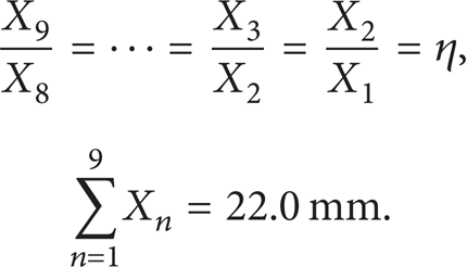
The variation range of η is 1∼ 1.6. The total length of the outlet section is a fixed value of 30 mm; thus different values of X1 to X9 are derived. Every portion stands for each hole between the two adjacent pin-fins at the chordwise outlet. Particularly when η has the value of 1, this represents that the 9 pin-fins are isometrically arranged at the outlet location. In this case, the arrangement of the distances between the outlet pin-fins can influence the mass flow rate of every hole, and then the inner cooling gas flow field will be changed indirectly. Finally, the cooling effectiveness of the blade trailing edge can be altered.
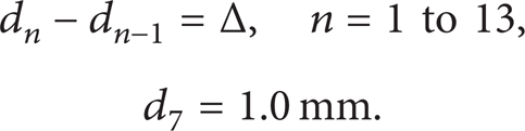
In Case 2, the diameter of the pin-fins in the radial direction (from d1 to d13) is set as an arithmetic sequence with the fixed η value of 1.2. The difference between each two inner adjacent pin-fins diameter is denoted by a parameter Δ, where the variation range is −0.1∼0.1 mm and the diameter d7 of the middle pin-fins is maintained the same value of 1.0 mm, which are expressed in formula (2). As different as Case 1, the parameter Δ can directly change the inner flow field; thus the cooling effectiveness is also altered:
2.2. Numerical Computation Process
2.2.1. Turbulence Modeling
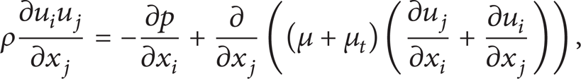
The numerical calculation uses the realizable K-∊ model (RKE) of Xie et al. [12] which is proved to be in a good agreement with the experimental data for the case of cylindrical hole. Brief introduction of the main equations is given here. For the details of the model, please refer to [13]. The governing equation for the flow and heat transfer can be expressed as follows [12, 13]:
continuity equation:

momentum equations:
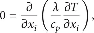
energy equation for fluid:
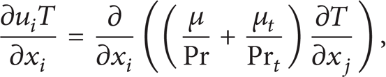
energy equation for solid:
turbulent kinetic energy k equation:

And in the turbulence model the coefficient σ k = 1.0.
2.2.2. Boundary Conditions
The static temperature and mass flow rate at the passage inlet are set to 880 K and 20.376 g/s, respectively, while the inlet turbulence level is set to 5% intensity. The average static pressure at the outlet is 0.8 MPa. Wall 1 is set as the adiabatic boundary condition while Wall 2 is the third heat transfer boundary condition in heat conduction within which the heat transfer coefficient is 2100 W/(m2*K) and the outside gas temperature of the blade is 1346 K. The boundary conditions, which are stated in all the computation cases, are shown in Table 1. In this paper, the fluid domain stands for the cooling gas and the solid domain represents the structure of the trailing edge of the blade.
Stated boundary conditions of the two domains in all models.

2.2.3. Grid
For all computation models, a kind of unstructured hybrid mesh was generated in both the fluid and solid domains by using the commercial software ICEM CFD. Flow region in the fluid zones near-pin-fins was meshed with denser grids of three prism layers due to the small circular holes produced by the pin-fins of the blade as shown in Figure 4(a). Moreover, in Figure 4(b), three prism layers were also set at the fluid-solid interface in the fluid domain. Three kinds of different amounts of grids about one model with η = 1 and Δ = 0 mm, namely, 1.77 M, 1.96 M, and 2.27 M cells, were analyzed, and the all-around property parameter Eu (10) was, respectively, 0.147, 0.1426, and 0.151, which showed that the influence of grid amount on the computation results can be neglected when the grids can get to about 2 M cells. Furthermore, the range of the nondimensional wall distances y+ of the first nodes near wall is about 20∼100.

Grids of the fluid domain (namely, the cooling gas) in all models. (a) Three prism layers around the small circular holes produced by the pin-fins of the blade. (b) Three prism layers at the fluid-solid interface.
2.2.4. Solver
In the process of numerical computation, the software CFX is utilized to compute. In pretreatment of CFX, the stated boundary condition of the two computation domains can be set. The minimum convergence criterion is set to 10−4 with the residual type of RMS in the CFX-Pre. At the fluid-solid interface, an energy balance is satisfied at every iteration, such that the heat flux at the wall on the fluid side is equal in magnitude and opposite in sign to the heat flux on the solid side. The fluid is assumed to be incompressible with constant thermal physical properties and the flow is assumed to be three-dimensional, turbulent, steady, and nonrotating. The working fluid is ideal gas. The blade is chosen as the aluminium material. In this study, the scalable wall functions of the RKE model are applied on the walls for the near wall treatment.
3. Results and Discussion
The study of this paper aims to investigate the best heat transfer and flow friction among all the computation models in the two cases, namely, Case 1 and Case 2. Several parameters are defined before analyzing and comparing the fluid flow characteristic and heat transfer. The friction f represents the flow characteristic while the average Nusselt number
The friction factor is defined as [12]

where u i is the inlet mean velocity and L is the total length of the cooling duct shown in Figure 3.
The average Nusselt number

where
For evaluating the cooling all-around property, the parameter Eu is calculated as [6, 9]

where the other two parameters
3.1. Case 1
Figure 5 shows the average Nusselt number and flow friction comparison when the outlet hole length proportion η changes from 1 to 1.6. With η increasing, the average Nusselt number

Comparisons of the average Nusselt number
The distribution curve of all-around property parameter Eu versus the outlet hole length η is shown in Figure 6. Eu has the decreasing trend when η increases. Eu synthesizes both the average Nusselt number

Distribution curve of the all-around property parameter Eu versus the outlet distance proportion η in Case 1.
3.2. Case 2
As the analysis of Case 1, we also investigate the fluid flow friction, the average Nusselt number, and the all-around property in this case. Figure 7(a) shows that the average Nusselt number

Comparisons of the average Nusselt number
Because of the friction f varying distinctly, the all-around property parameter Eu has the opposite change trend of it. As shown in Figure 8, Eu has the parabola increase trend and its maximum value is 2.564 times as much as the minimum value.
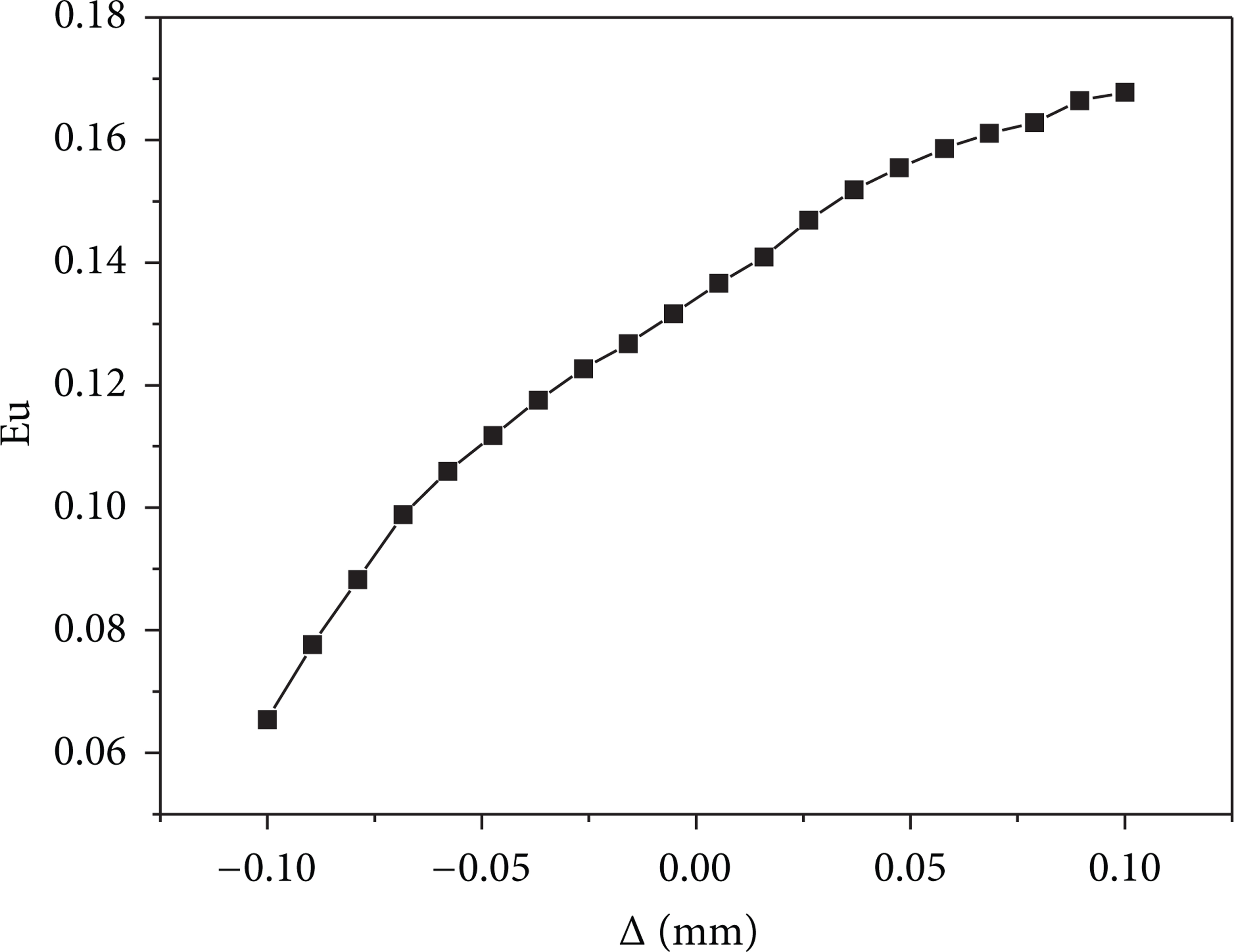
Distribution curve of the all-around property parameter Eu versus the inner pin-fin diameter difference Δ in Case 2.
4. Conclusion
In this paper, a new structural style of the pin-fins in the wedge duct has been proposed to find the best all-around cooling property through comparison. We studied the array distance of the pin-fins at the chordwise outlet and the arithmetic arrangement of the inner pin-fins diameter in the inner cooling gas passage to improve the cooling performance of the blade trailing edge. From all the foregoing analyses, the main findings can be listed as follows.
With the outlet hole length proportion η increasing, the average Nusselt number
When the inner and nonuniform pin-fin diameter difference Δ increases, the Nusselt number
In the design process of blade trailing edge, one meaningful suggestion can be concluded. Within the scope of safety design of the blade, the smaller the outlet hole length proportion η value and the bigger the inner and nonuniform pin-fin diameter difference Δ are, the better the cooling effectiveness and blade design will be.
Footnotes
Nomenclature
Acknowledgments
This work was supported by the National Natural Science Fundation of China (51210008, 51205315, and 51375387), Fundamental Research Fundation (JC20120230, JCY20130126, and 13GH014610) at Northwestern Polytechnical University, and 111 Project (B07050).