
Abstract
To achieve different demands for pressure control in managed pressure drilling (MPD), the relationship between the pressure difference and the valve opening was analyzed in the working process of MPD throttle. The throttle flow area equation and the flow area isosurface equation at different openings were derived. Then, the mathematical model of the throttle valve surface shape was established by solving the envelope curve of isosurface cluster. Furthermore, the shape curve equation of the valve core surface was derived and modified by applying this mathematical model. Finally, to verify the performance of this investigation, the comparison of the results between simulation and design values was performed. The results showed that the correlation between the throttle pressure difference and the valve opening is linearly related, which proves the correctness of the mathematical model for the throttle valve surface.
1. Introduction
With the growing exhaustion of the oil and gas resources, the exploration of the formation is becoming deeper and more complex. The complex drilling problems, such as the kick, well leakage, and the leakage of harmful gas, are increasing rapidly. As a new technology of oil drilling, the managed pressure drilling (MPD) can realize precise control in the whole drilling, pipe connection, and tripping processes by controlling the surface casing pressure, and it has become an effective way to alleviate these complicated situations previously mentioned [1, 2]. As one of the key equipment to achieve precise control of the wellhead back pressure in MPD, the throttle valve can be used to control the bottom hole pressure by adjusting the opening size of throttle valve to form different throttle pressures [3, 4].
With the development of MPD, the requirements of the wellhead back pressure control have gradually been transformed form high-pressure difference to high-precision control, and the study of the variation between the throttle pressure and the valve opening size has become the core problem [5]. As the main component of adjusting the throttle pressure in MPD, the shape curve of the valve core surface is directly related to the precision of the wellhead back pressure control [6]. At present, the valve core that is used in the conventional drilling consists mainly of needle valve core, cylinder valve core, and wedge valve core, for which numerous studies have been carried out and has already formed a perfect theory system. On account of the throttle valve that is used in MPD, some manufacturers suggest the use of throttle valve in conventional drilling and save the cost to a certain extent, but the throttle pressure with different openings present a nonlinear relationship that is prone to failure and hence cannot meet the requirements of MPD [7, 8]. Therefore, a special throttle valve used in MPD has been developed by T3 Energy Services and Expro International Group Ltd. [9]. The valve products of these two companies have been widely used by Schlumberger, Weatherford, Optimal, and other oil companies. In these throttle valves, the flow coefficient (Cv) changes with a linear relationship in the range of 30%–70% valve openings, but the throttle pressure changes nonlinearly which cannot meet all the conditions in MPD [10, 11]. Therefore, it is necessary to develop a new throttle valve, in which the throttle pressure changes linearly with the valve opening.
This paper studies the relationship between the throttle pressure difference and the valve opening in the working process of throttle valve in MPD and derives the throttle flow area equation and the flow area isosurface equation. Then, the mathematical model of the throttle valve surface shape is established by solving the envelope curve of isosurface cluster. Furthermore, the shape curve equation of the valve core surface is derived and modified by applying the mathematical model. Finally, to verify the performance of this investigation, a comparison of simulation and design values is performed.
2. Working Principle of the Throttle Valve
As a key equipment of controlling the wellhead back pressure accurately in MPD, the regulating performance of throttle valve plays an important role in the control precision of the wellhead back pressure. Figure 1 shows the sectional view of the throttle valve.
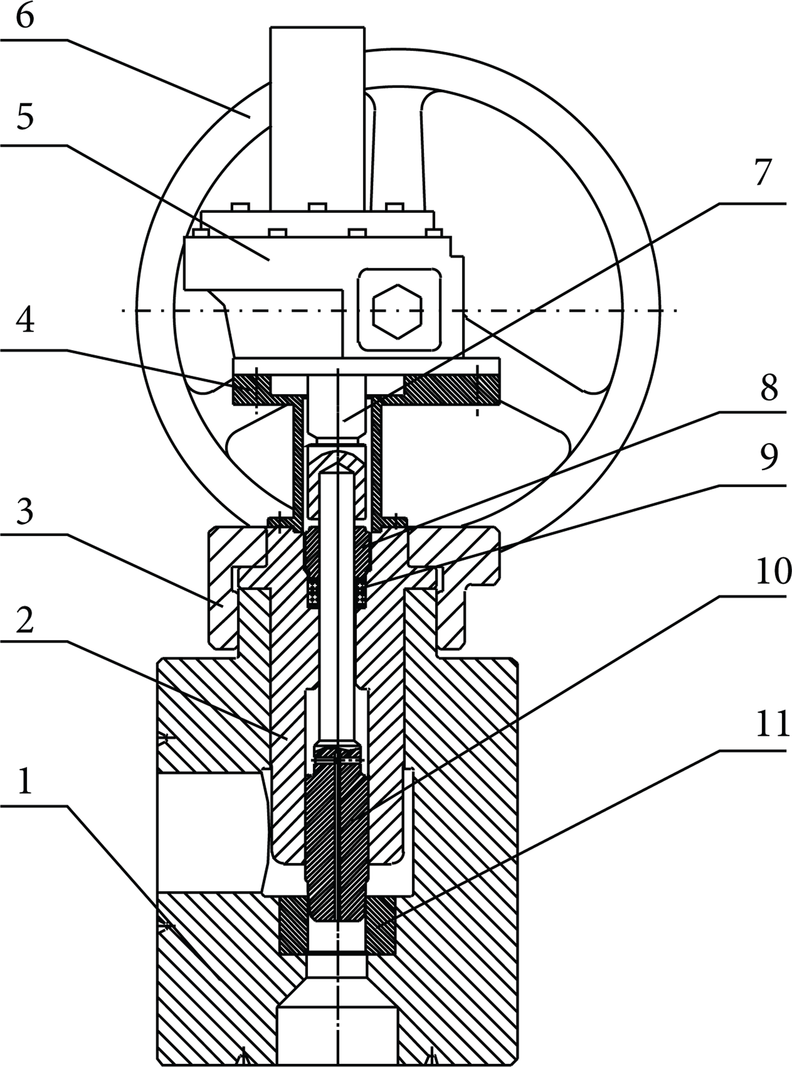
The throttle valve is mainly composed of a valve body, valve cover, screw drive assembly, valve seat, and a valve core assembly. The screw drive assembly is the central drive of the throttle valve to perform an action, and the valve core assembly is the key component to regulate the wellhead back pressure precisely. In the working process, the hydraulic motor or a hand wheel rotates the screw drive assembly which gives the spool assembly a vertical reciprocating motion, thus changing the valve opening. This provides adjustment in the throttle pressure and ultimately controls the wellhead back pressure.
3. Development of the Mathematical Model
Being the main component for adjusting throttle pressure in MPD, the valve core design is directly related to precisely control the wellhead back pressure. Therefore, the study and development of the mathematical model for the shape curve of the throttle valve core surface becomes the key point [12–16].
3.1. Pressure Characteristic Equation
According to the throttle pressure characteristics of throttle valve in MPD, the throttle pressure changes linearly with valve opening and is given by the following equation:

where Δp is the chocking pressure at one valve opening, Δp max is the throttle pressure at the minimum opening, Δp/Δp max is the relative pressure, l is the displacement of valve core at one opening, l max is the displacement of valve core at maximum opening, and l/l max is the relative displacement of the valve core.
From the boundary conditions

Substituting the boundary conditions into (1), the values of the K and C can be figured out as

Substituting (3) into (1), we can rewrite (1) as follows:

3.2. The Flow Area Equation
According to the flow equation of throttle valve


where Q is the volume flow rate, K v is the coefficient of flow, A is the flow area at the maximum opening, and ρ is the destiny of fluid.
Solving (5)-(6) simultaneously, the flow area equation of throttle valve can be written as

3.3. Mathematical Model of the Valve Core Surface
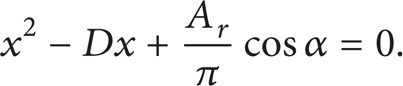
As shown in Figure 2, L MN is the minimum distance between the valve core and the valve seat, and the flow area A r is the lateral area of pyramidal face MNN1M1 at one opening.

Schematic diagram of the flow area.
From the lateral area equation of pyramidal face, the flow area A r can be calculated as

where


Solving (9)-(10) simultaneously, the flow area equation becomes
Substituting (7) into (11), the flow area equation takes the form

where D is the maximum diameter, α is the included angle, and x and y are, respectively, the transverse and longitudinal coordinates of N at the valve core curve.
Using M as the reference point at one opening, the level set curve is formed by the circular truncated cone at different α values, as shown in Figure 2. With the increase of the opening, the equation for the level set curve cluster can be written as

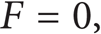
As an envelope curve cluster of F, the curve of the valve core must meet the following conditions:

According to (4a), the level set curve cluster at different openings can be written as
According to (14b),

According to Figure 2, the displacement of valve core at one opening l can be written as
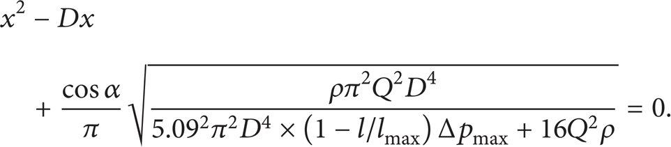
Equations (9), (15), (16), and (17) represent the mathematical model of the valve core which can be solved simultaneously

4. Solution and Curve Fitting
4.1. The Valve Core Curve Equation
To verify the validity of the mathematical model of throttle valve core, a project from Sinopec of China is used as a calculation example; the parameters of this example are shown in Table 1.
The data of calculation example.
A computer program was written for the mathematical model of throttle valve core and its coordinates were calculated at different openings. The results are shown in Table 2.
The coordinates of the valve core at different openings.
Fitting the coordinate values in Table 2, the shape curve of the valve core surface is shown in Figure 3.
The curve fit for the valve core using values from Table 2.
The curve fit equation of the valve core surface is

4.2. Modification of the Fitting Curve Equation
By calculating the distance between the valve seat surface and valve core curve, the minimum flow area was calculated using the equation A r = πL MN (D – x) and the correctness of the fitting curve equation was verified in comparison with the design values.
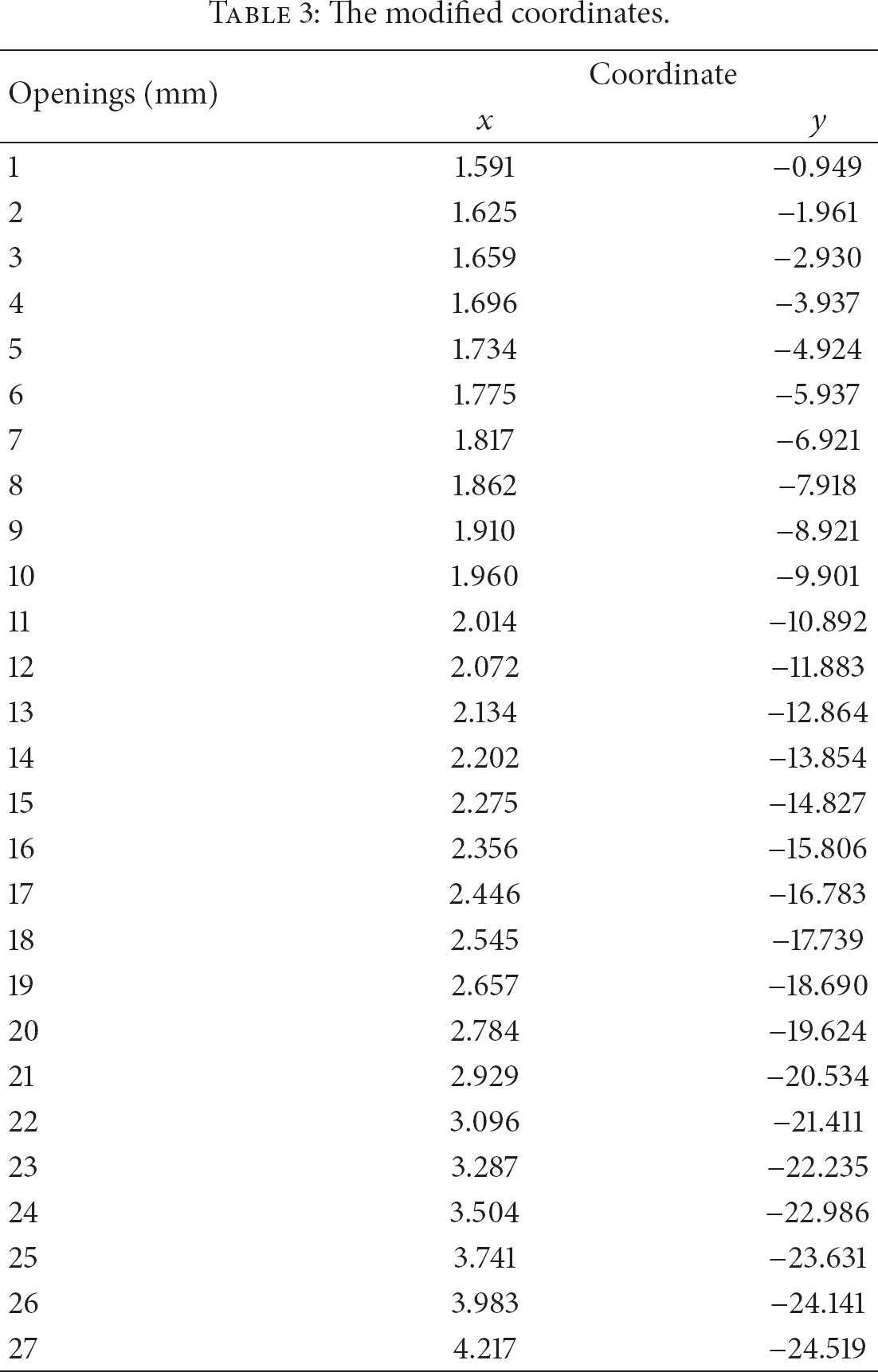
Fitting the coordinate values in Table 3, the modified shape curve of the valve core surface is shown in Figure 4.
The modified coordinates.

The modification of the valve core fitting curve.
From Figure 4, the modified curve fit equation of the valve core can be written as (20). Using this equation, a new throttle valve core can be designed and manufactured:

4.3. Relationship of Throttle Pressure with Different Openings
One has

From the flow equation of throttle valve, the throttle pressure is derived using (21) resulting in (22)

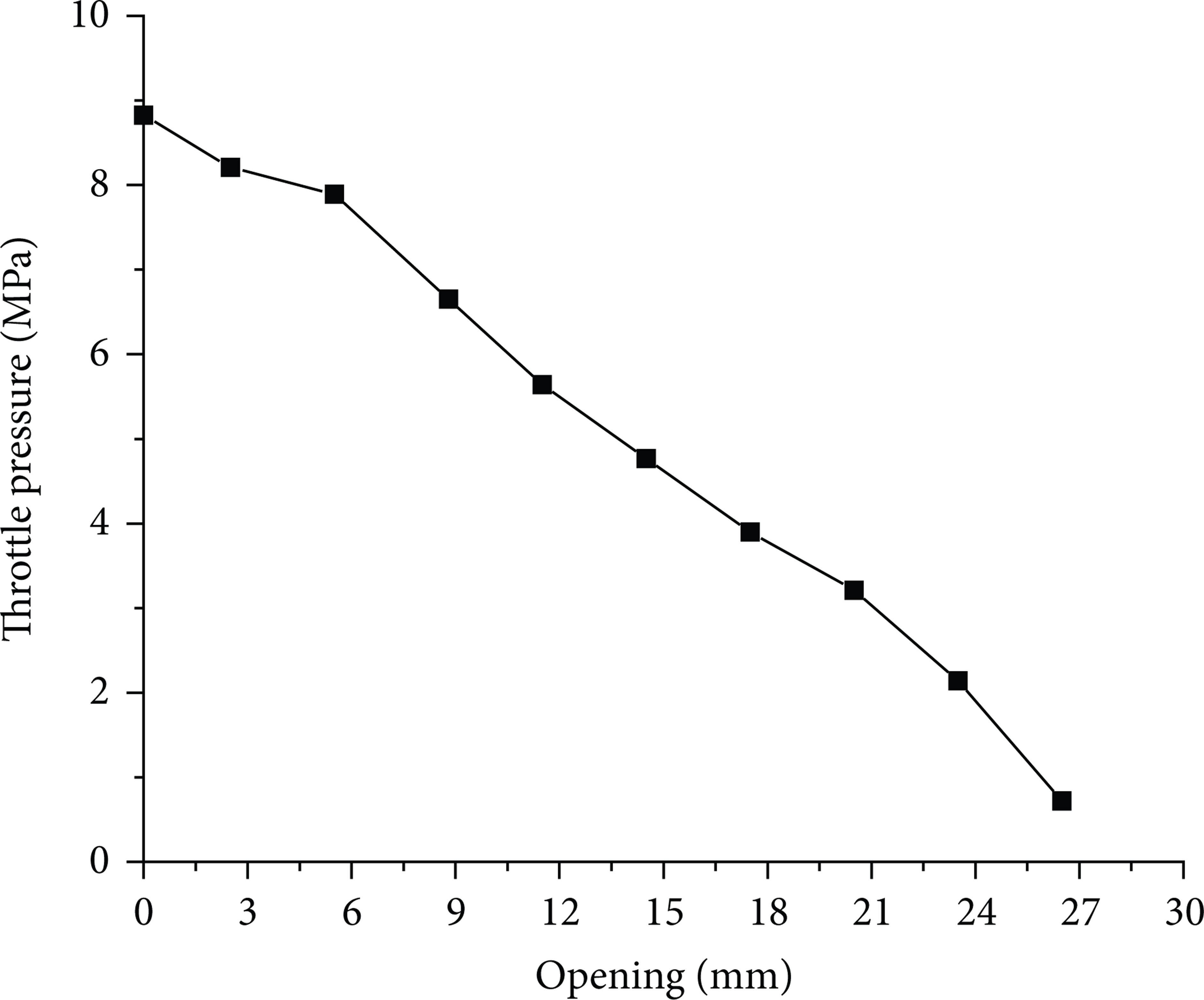
The throttle pressure can be calculated by (22) after the flow area at different openings is calculated by (7), and this relationship of throttle pressure with valve opening is shown in Figure 5.

The throttle pressure as a function of valve opening.
As shown in Figure 5, with the increase of the valve opening, the throttle pressure decreases linearly, thus making it easier to control the wellhead back pressure.
5. Comparison of Simulation Results with Design Values
The flow model at different openings is analyzed using computer simulation. The throttle pressure from the simulation results is compared with the design values, and the feasibility of the valve core is verified [17–20].
5.1. Simulation Modeling
Due to the fact that throttle pressure changes at different valve openings, the numerical simulation of three-dimensional flow model of Figure 6 is studied at ten different valve openings [21, 22], and the results are shown in Figure 7.
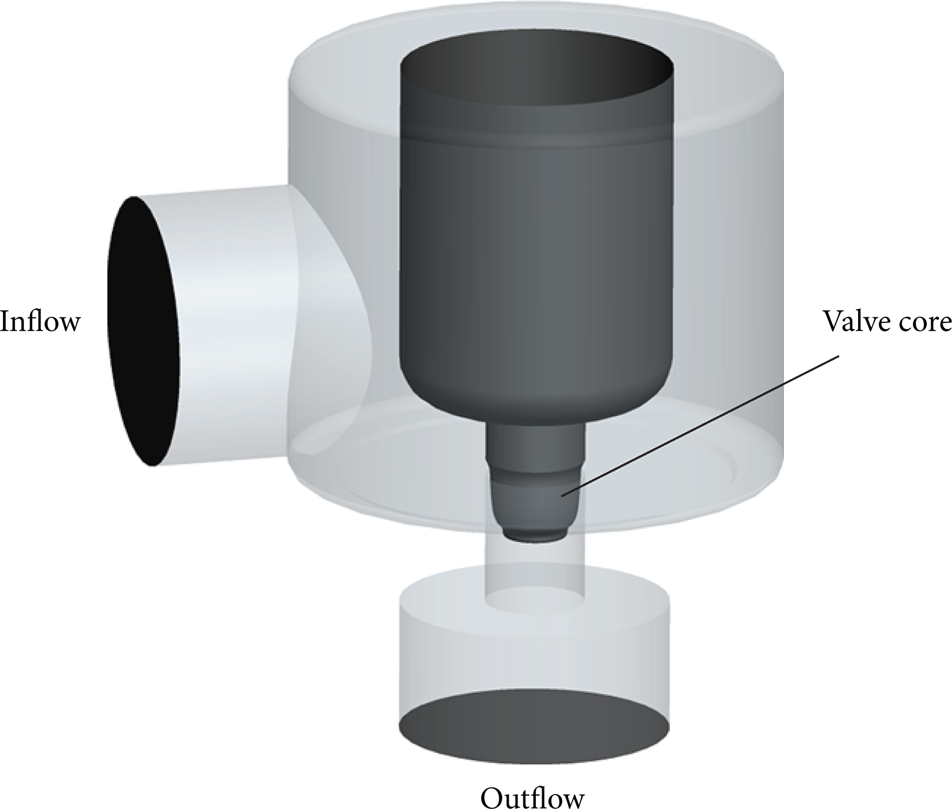
The three-dimensional flow model.
Simulation results of throttle pressure at different openings.
The maximum throttle pressure is found to be 8.825 MPa at an opening of 0 mm, and the minimum throttle pressure is 0.722 MPa at an opening of 27 mm. The throttle pressure decreases as the valve is opened gradually and this decrease is approximately linear.
5.2. Comparison and Validation
To verify the feasibility of this design, the simulation results of throttle pressure are compared with the design values.
Figure 8 shows the variation of the designed throttle pressure with simulation results at different openings. The simulation results of throttle pressure are a little smaller than the design values when the opening is between 0 and 18 mm, they are almost equal when the opening is between 21 and 24 mm, and they are little smaller at an opening of 27 mm. The numerical simulation accuracy is affected by number of cells in the computational grid quality and other factors, and the small deviation of throttle pressure between the simulation and design values can hardly be avoided. Therefore, the simulation results of throttle pressure with the design values are nearly the same, which verifies the correctness of the design of the valve core.

The comparison of the design values with simulation results at different openings.
6. Conclusions
The pressure characteristics of throttle valve in MPD are fully considered, and the mathematical model of the valve core surface is derived, solved, and modified. The throttle pressure of the throttle valve at different openings is solved with the modified equations of valve core surface, and the variation of throttle pressure with valve opening is approximately linear. Based on the simulation analysis of flow model at different openings, the variation of simulated throttle pressure with valve opening is approximately linear. The simulation results of throttle pressure with the design values are nearly the same, which verifies the correctness of the design of the valve core surface.
Footnotes
Acknowledgment
The work was supported by the Natural Science Foundation of China (Grant no. 51134004).