
Abstract
This paper presents a novel collaborative beamforming (CB) method of wireless sensor network (WSN) by organizing sensor node location in a circular arrangement. Appropriate selection of active CB nodes and cluster is needed each time to perform CB. The nodes are modeled in circular array location in order to consider it as a circular antenna array (CAA). This newly proposed circular collaborative beamforming (CCB) is further presented to solve two different objectives, that is, sidelobe level (SLL) suppression and first null beamwidth (FNBW). Analyses obtained are compared to those from previous work. The findings demonstrate a better CB performance of intelligent capability, and the difference is shown in normalized power characteristic.
1. Introduction
Inside WSN environment, collaborative beamforming (CB) can be beneficial in increasing signal to noise ratio (SNR), thus boosting the energy efficiency of the system. In contrast with direct transmission transmitter-receiver or hop-by-hop transmission, CB spreads the energy consumption over multiple transmitters and improves the signal strength at the receiver [1]. Therefore, the CB nodes need less energy for data transmission, thus balance the energy consumptions, and desirably extend the network lifetime.
Works supporting sensor network in the literature, which utilizes wireless array, including [2–4] investigated usefulness of method and implementation schemes of a transmission array. Gaussian probability density function (pdf) is utilized to model the spatial distribution of sensor nodes in a cluster of WSNs [2] by proposing node selection algorithm [5]. The impact of Gaussian pdf as the spatial distribution is explored on the beampattern characteristic and compared with similar case when uniform pdf is used in [6]. The algorithm is developed to control the sidelobes by searching over different node combinations [7]. Ahmed and Vorobyov consider the random nodes deployed in Gaussian pdf, while the proposed work considers the uniform random nodes distribution.
In spite of the significant contributions from previous literatures on CB, none of the works offer a CB by implementing circular antenna array (CAA). To the best of the authors' knowledge, this is the first work dealing with this problem. In this paper, the circular array technique is specially designed for WSNs with intelligent capability. The conventional uniform circular antenna array (UCA) may not be directly applied in WSN as it requires the exact location of elements in circular arrangement, a requirement that does not conform with random distribution nature of sensor nodes. Therefore, this is the main challenge of adapting this CAA into the context of WSN environment.
This paper presents a novel method of optimizing sensor node location in a circular arrangement. In this problem, the appropriate selection of active CB nodes and cluster is needed at each time to perform CB in WSN. The nodes are modeled in circular array location in order to consider it as a CAA. In the preliminary version of this work [8], it is shown that the linear sensor nodes array (LSNA) is able to achieve a desirable adaptive beampattern with narrow main lobe and acceptable sidelobes level (SLL). Novel concept is offered with regard to intelligently optimizing and locating the selected sensor nodes to participate and form an array of sensor nodes. The concept is extended here through an alternate approach which employs hybrid least-square speedy particle swarm optimization-based circular collaborative beamforming (HLPSO-based CCB). The earlier work is reported in [9]. The biologically-inspired algorithm of particle swarm optimization (PSO) algorithm is improved and utilized to select the optimum nodes to participate in CB. The objective is to keep the main advantages of the standard PSO, such as simple implementation, low algorithmic complexity, and few control parameters, while maintaining the performance. Therefore, the proposed HLPSO characteristics are particularly attractive for WSNs since the computational resources such as memory and energy are limited.
The main idea in the proposed method is the desired objectives of radiation beampattern with minimum SLL and controllable size of FNBW. The proposed intelligent method of HLPSO-based CCB for determining optimum location of sensor node is proved superior to alternate techniques in terms of the normalized power gain with desired objectives. Up to date, an intelligent approach to determine optimum sensor nodes location to participate in wireless array network by employing bioinspired algorithm has not been reported or published so far by other authors.
2. The Network and Geometrical Array Model
2.1. The Network Model
WSN consists of a large number of sensor nodes in random deployment, which are wirelessly connected. The nodes are self-organized and are in connection with a controlling station as described in [10]. Each sensor node's location is determined using location discovery techniques [11] and is reported back to the controller. The central processor in a controlling station has detailed knowledge of each sensor node's location. It is also capable of selecting the appropriate manager node (MN), thus active cluster (AC) as per user requirement. Each sensing node,
2.2. The Geometrical Array Model
The collaborative array antenna radiates power in all directions; hence, the simulation work should be in 3-dimensional scope. It is assumed that all sensor nodes are located on a 3-dimensional


3. Hybrid Least-Square Speedy Particle Swarm Optimization (HLPSO)
PSO is applied to determine the optimum distance location of the nodes, which performs the highest performance as refer to objective scopes. Some improvements have been adopted in original PSO [13] in order to overcome the weaknesses and to adapt the algorithm inside WSNs environment. The novel HLPSO is proposed by integrating two novel mechanisms, that is, constraint boundaries variables and particle's position and velocity reinitialization. Moreover, the least-square approximation algorithm (LS) is integrated into it to improve the effectiveness and the capabilities of PSO in CCB application.
3.1. Global Constraint Boundaries Variables
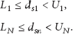
Two sets of global constraint boundaries variables for lower boundary L and upper boundary U for different position particles,

3.2. Particle's Position and Velocity Reinitialization
The random numbers of particle position

3.3. Hybrid Least-Square Particle Swarm Optimization-Based Circular Collaborative Beamforming (HLPSO-Based CCB)
The proposed network model of HLPSO-based CCB consists of a random deployment of Z stationary sensor nodes inside the region of interest of
There are three phases in HLPSO-based CCB: parameter initialization, activation, and optimization setup phases. The flow chart for the three phases of HLPSO-based CCB has been shown in Figure 1. A description of each follows.

Flow chart for HLPSO-based CCB.
3.3.1. Parameter Initialization Phase
The initial parameters for WSNs environment are listed in Table 1.
Parameters and values of 8-node CCB.

The proposed HLPSO manages to search for the optimum element distance of CCB and deal with the desired objectives. The desired parameters for HLPSO are illustrated in Table 2. These parameters are initialized by referring to the desired objectives of the organization scheme.
List of parameters used in HLPSO implementation.

3.3.2. Activation Phase
MN with coordinates of (
3.3.3. CCB Optimization Setup Phase
The procedures needed to formulate this CCB optimization setup scheme are described as follows.
Step 1.
Construct the virtual circle with C radius by referring to MN as the center of the circle.
Step 2.
Establish HLPSO algorithm to optimize the sensor node location.
Step 2(a). Initialize HLPSO parameters.
Step 2(b). Generate random initial location,
Step 2(c). Calculate the objective function, that is, 

Step 2(d). Determine the previous best location,
Step 2(e). Determine the global best position,
Step 2(f). Update 
Step 2(g). Update 
Step 2(h). Update
If
Step 2(i). Update
If
Step 2(j). If the maximum iteration number is met, terminate the algorithm, otherwise, proceed to Step 2(c).
Step 3.
Construct CAA by using the distance result
Step 3(a). Calculate the radius, 
Step 3(b). Calculate phase 
Step 3(c). Convert the polar coordinates 
The construction of this optimum CAA is illustrated in Figure 2. The MN is located at the centre of

Locations of
Step 3(d). Determine the normalized gain,
Step 4.
Start searching CCB nodes.
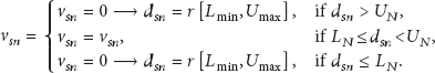
Step 4(a). Select the minimum Euclidean distance, 
Step 4(b). Choose the
Step 4(c). Activate
Step 4(d). This set of optimal CCB will be performed collaboratively as an N-element distributed CAA.
Step 5.
Determine normalized gain,
Step 6.
Change radius of both
Step 6(a). Return to Step 1 for different virtual circles.
Step 6(b). Compare the radiation beampattern performance results for different r values.
Step 7.
Select the best solution.
The final solution from the proposed CCB is to select the active nodes to perform CB. The intelligent feature in this proposed algorithm is how the algorithm managed to select the best team of active nodes to accomplish CB with user desired requirements. Examples of such requirements are the desired radiation beampattern with minimum SLL and expected size of FNBW. Results are then validated with UCA [12] and circular sensor node array (CSA) as evidence of the effectiveness. Active nodes of CSA are selected based on the UCA, which has the nearest location to nodes of UCA. In CSA optimization setup phase, Step 2 of establishing HLPSO is not included because the distance between nodes
4. Results and Analysis
The computed optimization results in radiation beampatterns are analyzed in different cases of N-node CCB with different objectives. The validation performances are demonstrated between CCB and corresponding results obtained from the CSA and conventional UCA [12].
Figure 3 illustrates the simulation scenario for 8-node CCB in MATLAB environment. It shows the random deployment of Z nodes inside the area of interest, that is,

Randomly deployed Z nodes with selected MN and AC.
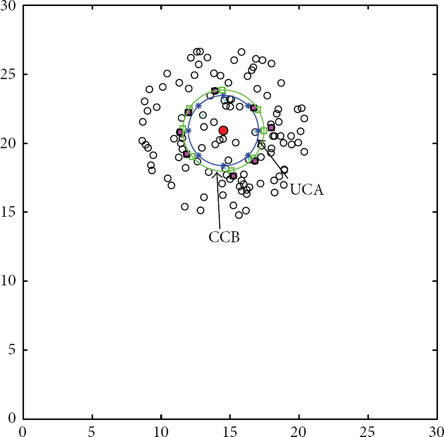
Virtual circles (a) blue depicts UCA and (b) green depicts CCB, and nodes (c) blue stars depict
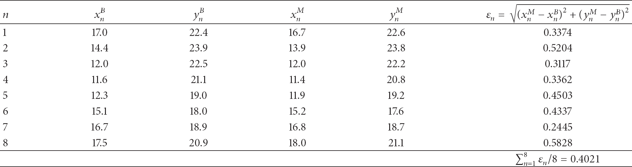
Table 3 lists the x- and y-coordinates for
Coordinates of
4.1. Sidelobe Level (SLL) Suppression
In the proposed CCB, SLL can be successfully suppressed to increase the received power at the receivers and to avoid interference from other interrupting access points or clusters or prevent these access points or clusters from recovering the transmitted signal. Figure 5 demonstrates the computed normalized gain for 8-node CCB at
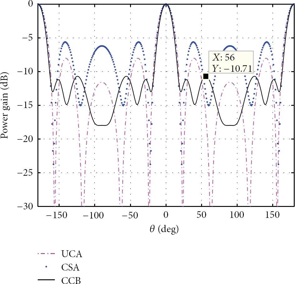
Radiation beampattern of 8-node CCB with SLL minimization.
The optimization then considers a circular array with FNBW of 38° with the main beam angle pointing towards

Radiation beampattern of 8-node CCB with SLL minimization.
The next case considers 12-node CCB. It demonstrates the different effects on the radiation beampattern performance with different arrangements of the node location. It can be seen from Figure 7 that the conventional UCA exhibits relatively high SLL at −131°, −49°, 49°, and 131°, which is similar to CSA. The maximum SLL of CCB shows degradation, that is, decrease of 5.02 dB, compared to the maximum SLL of UCA (i.e., −2.19 dB at 49°).
Radiation beampattern of 12-node CCB with SLL minimization.
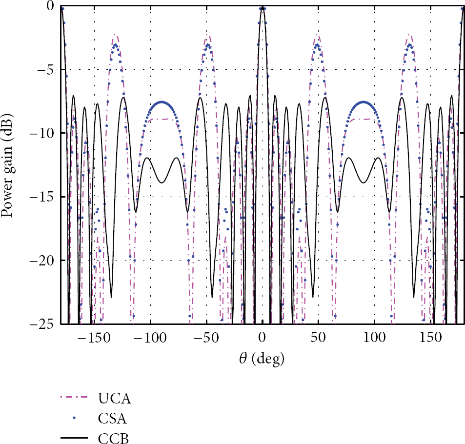
16-node CCB is then considered. It can be observed from Figure 8 that the highest peak SLL of approximately −4.32 dB exists at −109°, −71°, 71°, and 109° for both UCA and CSA. However, CCB managed to greatly minimize the SLL until −14.30 dB at the respective angles. As the number of CB active nodes increases, it not only can increase the gain but also narrows the FNBW as desired. In this case of 16-node ICSA, the FNBW is only 14°.

Radiation beampattern of 16-node CCB with SLL minimization.
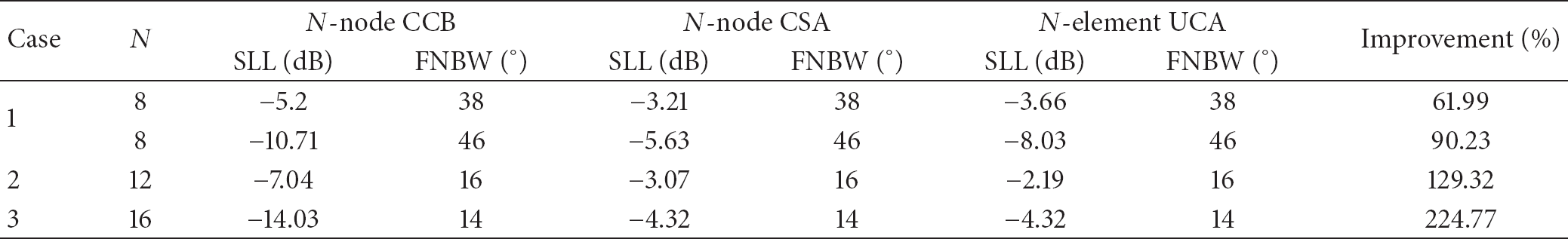
Three cases are analyzed with different numbers of CCB nodes as shown in Table 4. From the results, it is noted that this newly proposed CCB can overcome the undesired increment of the SLLs in UCA and CSA by intelligently optimizing the participating CB active nodes.
Percentage improvement of SLL performance for CCB in different cases.
4.2. Controllable First Null Beamwidth (FNBW)
An advantage of CCB over UCA and CSA is that the CCB has the capability to adjust the desired amount of FNBW. It is essential to control FNBW in order to decrease the energy consumption. The size of FNBW is needed to be narrower for data transmission to focus the radiation to the attempted destination. In contrast, the size for FNBW is needed to be wider for direction-finding applications.
It reveals the different effects on the size of FNBW performance with the different arrangements of the node location. The radiation patterns of 8-node CCB are plotted in Figure 9. It illustrates a smaller radius of CCB with

Radiation beampattern of 8-node CCB with wider FNBW.

Radiation beampattern of 8-node CCB with narrow FNBW.
Next case considers 12-node CCB with

Radiation beampattern of 12-node CCB with narrow FNBW.
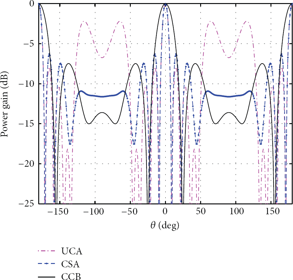
Radiation beampattern of 12-node CCB with wide FNBW.
It can be observed that a good performance of radiation pattern is obtained from CCB as compared to the previous CSA. It is also shown that different radii contribute to different performances of CCB. In addition, it is noted that the 12-node CCB with FNBW of 50° maintains low SLL throughout the angles that is less than −7.483 dB. Therefore, it is proven that, by implementing the objective function together with CCB, the desired FNBW can be controlled that simultaneously improved the SLL suppression.
5. Conclusion
The problem of array beamforming is the presence of error beampattern caused by random sensor position errors. The proposed CCB can effectively improve reliability, capacity, and coverage by intelligently adjusting the shape of the beam patterns under different constraints, either by suppressing the SLL or managing the size of FNBW as per desired usage. The proposed CCB has the ability to select the active CB nodes and dynamically control the radiation beampattern to enhance the reception while minimizing the interferences using the proposed HLPSO-based CCB algorithms. The radiation beampattern expression of the proposed CCB is obtained, and it is further proved. Different properties of the radiation beampattern have been successfully analyzed and proven.
Footnotes
Acknowledgments
The work is supported by Universiti Teknologi Malaysia and Ministry of Education Malaysia, RUG vote PY/2012/01578 and FRGS vote 4F039.