
Abstract
Due to such requirements as low power consumption and low cost, sensor nodes commonly do not include advanced H/W features. The absence of the features such as the memory management unit enforces several tasks to share a memory address domain on a small data memory space (1~16 KB). It exposes each task to the stack overflow causing the corruption of other memory areas. In this paper, we propose a robust and efficient stack memory management method (RESM) that dynamically assigns and releases a preestimated amount of stack memory to each function call at runtime. RESM maintains the stack memory usage with the similar amount of the stack usage that the system actually requires, and the stack memory area of each task is individually protected from corruption by the stack overflow. RESM can also anticipate a saturated condition in data memory at runtime. When the memory state is unsafe from the saturated condition, it conditionally allows function calls to operate tasks without any memory fault by using the proposed function call deferring algorithm. From the analytical and experiment results, it is proven that the performance of RESM outperforms the other mechanisms and RESM can provide more robust stack operation environment.
1. Introduction
Recently, the development of the semiconductor has enabled cheap, low power, and small-sized sensor nodes with the computing and communication capabilities [1]. Accordingly, wireless sensor networks (WSNs) that consist of a large number of sensor nodes have attracted considerable attention in both academy and industry because of their great potential for realizing ubiquitous environment. Despite the simplicity of the sensor node hardware, there has been an increasing demand for diverse WSN applications, such as military surveillance, habitat monitoring, U-health care, and infrastructure protection [2–6]. Accordingly, the role of the operating system (OS) that bridges the gap between H/W simplicity and application complexity becomes important [7]. OSs for a WSN (sensor OSs) can be designed using two scheduling policy approaches: event-driven task scheduling and multithreaded task scheduling [8–15]. Although the event-driven task scheduling approach, which provides run-to-completion semantics for tasks, is commonly adopted due to its simplicity of implementation and suitability for the sensor nodes with scarce H/W resource, sensor OSs based on multithreaded task scheduling have been steadily developed due to such advantages as user-friendly development environments, real-time support, and robustness which are obtained from the concurrent operation. These advantages enable multithreaded task scheduling to be more attractive for the applications with a time requirement and easy to develop for a large system in a cooperative manner [7, 13].
As many WSN applications require unattended operation for a long lifetime, one of the most important roles of the sensor OS is to ensure the reliable execution of applications. However, it has been a challenging issue to provide reliable services on a sensor node, which typically possesses scarce available H/W resources due to such requirements as low power consumption and low cost. These requirements enforce the sensor node to consist of simple and cheap H/W elements, a microcontroller unit (MCU) and RF module, providing only basic functions. MCUs that are commonly used on sensor nodes, MSP430 series [16] and ATMEGA series [17], do not include advanced H/W features, such as privileged mode and a memory management unit (MMU), to provide a reliable environment for S/W execution [13, 18, 19]. The absence of these features can easily expose a system to control hazards and data hazards, respectively. The problems caused by this absence can be especially significant for multithreaded task scheduling. The absence causes several tasks to share a memory address space, while each task requires an exclusive stack memory space even on a small data memory space of approximately 1~16 KB. A shared small memory space between tasks increases the probability of the stack overflow. For example, the overflow of a stack area can cause corruption of the memory areas belonging to other applications and the kernel. The corrupted areas may include dynamic, local and global variables, return addresses, and even critical MCU registers, which can cause a malfunction of the entire system.
As shown in Figure 1, the data memory is vulnerable to data corruption by buggy programs or stack overflow. Whereas logical faults in buggy programs can be detected and debugged by developers before their execution, it would demand enormous time and efforts to detect or anticipate stack overflows because all instructions related to the stack operation are internally generated by the compiler. The usage of stack memory also fluctuates according to the progress of program execution and heavily depends on a developer's coding style. Moreover, poor debugging environments for the WSN application development make it more difficult to debug or anticipate stack operation.

Example of memory corruption.
There are some researches for preventing the stack overflow in WSN [13, 18–23]. Without the hardware features, most methods combine compile-time instrumentation and run-time checking, that is, they analyze the program and insert hooks at compile-time, then execute these hooks at run-time to ensure system reliability. In a sensor OS based on multithreaded task scheduling, each task needs its own stack memory space in resource-constrained sensor nodes with small memory footprints. Accordingly, precise management of stack memory is required to prevent the increasing possibility for confliction between stack areas. Most previous researches focus on preventing the overflow by estimating the maximum amount of stack per each function call, each task, or a system. However, they do not detect a saturated condition in data memory at runtime. The saturated condition can occur due to the increase of tasks and indirect or direct recursive calls. In the saturated condition, an additional stack use causes the stack overflow. Accordingly, the runtime detection of the saturated condition should be considered to completely prevent the stack overflow.
In this paper, we propose a robust and space-efficient stack memory management method (RESM) that can individually protect the stack memory area of each task from corruption and can dynamically maintain the allocated stack memory space to the amount actually required by the program at runtime. The basic concept of RESM is simple. The code analyzer scans C and assembly codes to estimate the stack box size for each function. A stack box (SB) is defined as stack space, in which a function can operate its stack without the stack overflow. When three tasks simultaneously call an identical function,
We organize the rest of this paper as follows. In Section 2, we describe the previous works related to memory protection for sensor OSs. In Section 3, we explain the code analyzer, the memory structure, and the SB manager for RESM in detail. Then, in Section 4, we evaluate the performance and the overhead of RESM using numerical results and simulation results. Finally, conclusions are presented in Section 5.
2. Related Work
There are various researches to prevent the stack overflow on sensor nodes. Some researches such as [13, 18, 19] prevent the memory access violation by examining the instructions related to the memory access at runtime. Cha et al. proposed RETOS [13], a multithreaded task scheduling system that provides dual-mode operation to ensure kernel data integrity. Destination fields and source fields for all instructions related to memory access are examined to prevent applications from reading the kernel or other applications' data. RETOS allocates each task with a stack memory space, which is statically estimated using a control flow graph and a depth-first search. However, it overestimates the stack memory and does not consider stack memory for ISRs. Gu and Stankovic presented t-kernel [18] to modify application code at load-time to ensure OS responsiveness. Kumar et al. proposed Harbor [19] for per-domain memory protection in SOS and event-driven task scheduling. Harbor inspects all instructions related to memory access to each domain to verify the validity of the access, using the memory map. Harbor also assigns a part of data memory to a safe stack, in which return addresses for all function calls are stored. Because the memory map contains ownership information (a domain identity) for every block of memory, the memory space for the memory map depends on both the block size and the number of domains. Assuming a 4 KB data memory, a block size of 8 bytes, and 8 domains, 256 B should be allocated to the memory map, 6.25% of total data memory. In [13, 18, 19], the large memory space is required for maintaining the information for all memory sections, and the large computing time is consumed for examining the instructions related to the memory access at runtime.
Some researches such as [20, 21] use the fixed stack memory allocation. They estimate the maximum stack memory usage needed to execute a system, considering all tasks and interrupt service routines, and they statically allocate the estimated stack memory space. Because the stack memory usage varies according to the progress of a program execution, allocating a fixed stack memory space produces a relatively large internal fragment. In addition, the stack estimation using a call graph tends to overestimate the stack memory required. In [20], although authors reduce the stack usage based on analysis of the abstract interpretation, a considerable time is required for the analysis. In sensor nodes with scarce resource, the inefficient memory use and the time overhead degrade such performance as the decrease of task capacity and the response time.
Heo et al. proposed the shared stack management for the cooperative threads. In [22], all the cooperative threads share a single stack. The only the stack of the currently running thread occupies the shared stack at a time. When a thread suspends at the preemption points, it allocates a buffer into a head and it then copies its thread context to the buffer. The thread that will next run copies its stack to the shared stack, and it then resumes its execution. Thus, one context switching requires additional computing time for stack switching and memory compaction. In [22], the authors try to reduce the number of compactions that remove external fragmentation caused by thread switching. The work in [22] determines whether one context switching involves the compaction, based on the overflow probability. The probability is calculated based on the number of push operations at the assembly code level. However, in a task for sensor applications, the depth of a stack depends on the flow control and the characteristics of the event triggered. Accordingly, the overflow probability based on counting push operations at the assembly code level cannot reflect the current stack movement. In addition, although the cooperative threads can decrease the number of context switching compared to that of the general multithreaded system, the frequency of context switching can greatly increase as intended interrupts or events occur more frequently. In this situation, the response time of a system can be greatly degraded as the larger portion of computing time is wasted for swapping the stack due to the frequent context switching.
Yi et al. proposed the dynamic stack allocation methods, SESAME [23] and OTL [24]. The works of [23, 24] estimate the stack amount for each function call at the assembly code level. At runtime, they dynamically allocate the stack memory block at each function call and release the memory block after the function returns. To allocate and release memory blocks, they use “malloc()” and “free()” APIs in the library. The works of [23, 24] allocate a stack memory block as much as a function call requires. The basic concept for SESAME and OTL is similar to RESM. However, several problems have not been solved. First, they do not consider a saturated condition of data memory. In the resource constraint sensor nodes, a saturated condition can easily occur as the number of tasks rapidly increases due to bursts of targeted events. Although there is no available memory space, tasks in [23, 24] continuously request additional stack memory at the entries of function calls in the saturated condition, and then system is halted. Since [23, 24] do not propose any method to detect and handle the saturated conditions, the only way to resolve deadlock problem would be system reset. Second, they propose only a concept for stack management per a function call. To implement this concept in the sensor node, several consideration points have not been solved. For example, they do not consider an additional stack space caused by context switching although the multithreaded OS is targeted. Typically, the information of some MCU registers is pushed into the current stack to save the current context at a task switching or at a jump to ISR. Accordingly, an estimated stack space in [23, 24] can easily overflow when an interrupt or a task switching occur during the execution of a subroutine. This is a critical problem in the multithreaded OS. Also, they do not suggest how to allocate, release, and manage memory blocks. It seems to use such “malloc()” and “free()” as the library APIs in the compiler or the OS. The use of the library makes the performance, for example, the time to search empty memory blocks, and the space overhead to maintain the blocks, of [23, 24] nondeterministic since it depends on the used library.
3. Robust and Space
Efficient Stack Memory Management Method (RESM)
3.1. Stack Box
We define a stack box (SB) as a stack memory space needed to execute a function or an interrupt service routine (ISR) without any stack overflow at runtime. Figure 2 shows the example of SBs for two functions and an ISR. The actual memory allocation for a SB occurs at a call to either a function or an ISR. The multiple calls of a function result in the residence of the multiple SBs corresponding to the function in data memory. An SB is allocated when a function or an ISR is called and is released when the function or the ISR returns in data memory. An SB does not include additional SBs for other function calls occurred during the execution of a function or an ISR. Therefore, an SB for a function or an ISR can be estimated as the sum of the stack depth caused by local variables, arguments, a return address, and context information. The context information means a set of information that must be saved to store the context at a point and to continue the execution at that point at an arbitrary future time. The content of context information depends on MCU manufacturers. It commonly includes some MCU registers, for example, stack pointer (SP), program counter (PC), and some general-purpose registers. When the program flow deviates from a function due to an interrupt event or task switching, the context information is pushed to save the current context into the SB of the function. On the contrary, it is popped to restore the previous context from the SB when the function retrieves the program flow again. Considering that the deviation of the program flow occurs only once within a function or an ISR at a time, the space for one context information is included in an SB. An SB for a function x,


Example of stack boxes.
3.2. Data Memory Structure
In RESM, data memory is divided into equal-sized blocks, and the size of a block follows the form of the nth power of 2 in bytes. A block is the unit of memory allocation for SBs. In RESM, a part of data memory is exclusively assigned to a memory map that contains per-block occupancy information for an entire data memory space. The memory map is formed into a bit string in which each bit represents the availability of a block as 1 or 0; a bit set to 0 means that the corresponding block is empty and able to be allocated for any SB; a bit set to 1 indicates that the corresponding block has been already allocated for another SB. The most significant bit (MSB) of the memory map corresponds a block located at the highest address in data memory. The bits after MSB are sequentially mapped to blocks after the block of the highest address. The value of n is closely related to the memory overhead. Setting n to a larger value can produce more internal fragments in SBs, but the size of the memory map that maintains the occupancy information of blocks decreases. On the contrary, setting n to a small value can decrease internal fragments in SBs, but more memory space is required for storing the memory map. The space for the memory map,


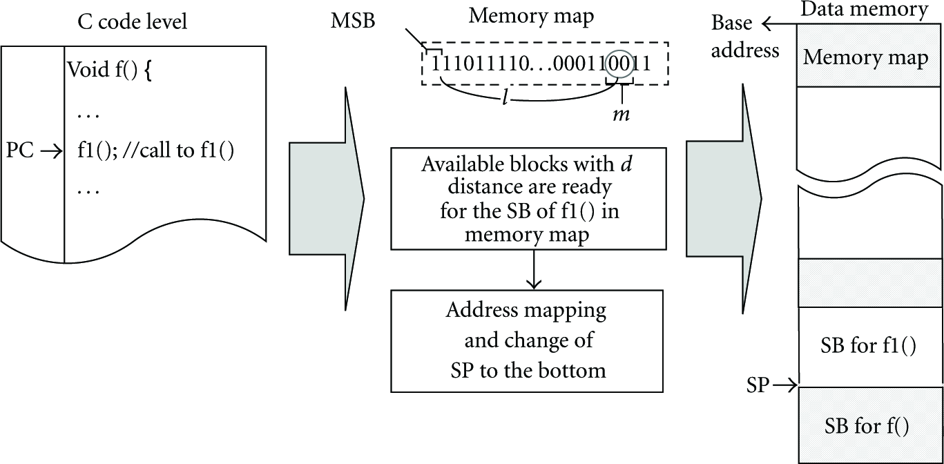
Example of address mapping.
3.3. Code Analyzer
For RESM, all source codes need to be analyzed and modified before compiling.
We developed a kind of preprocessor, called the code analyzer, which estimates the sizes of SBs for all functions and inserts the SB manager into intended points at C code level. The code analyzer analyzes both C code and assembly code translated by the compiler with the optimization option, respectively. Some user-defined functions in C code can be removed through code optimization during compiling when the compiler decides that the functions are meaningless or require no stack memory. Thus, the optimized assembly code is firstly analyzed to identify active functions, which are not removed from the code optimization and require a stack memory space at runtime. Then, the analysis of C code is conducted to measure the size of the user-made types, for example, structures, and to estimate SBs for all active functions and ISRs. After that, the code analyzer scans C source code to find points, into which the SB manager is inserted. After cross-compiling the source files containing the SB manager and downloading the object file on sensor nodes, the SB manager hooks the program flow at the inserted points and transparently performs the intended tasks such as allocating and releasing SBs for RESM. The SB estimation at C code level can cause overestimating the size of an SB because some local variables and arguments can be replaced with general-purpose registers through compiling with optimization option and, thus, does not consume stack memory at runtime. However, the stack movement can be examined more exactly at C Code level than at assembly code level. All instructions related to stack operation, for example, PUSH, POP, and arithmetic operation for SP, are automatically created by the compiler, and the operands for the instructions can be used in several addressing modes such as the immediate, direct, or indirect addressing mode. Except for in immediate address mode, it is hardly possible to anticipate the movement of SP from the analysis of assembly code. Moreover, the module insertion at C code level can be more portable due to independence on compilers and MCUs. Figure 4 shows the procedure of the code analyzer for an SB manager to be invoked at runtime. The code analyzer also modifies interrupt service routines (ISRs). The code analyzer switches all user-registered ISRs to functions and it redefines the ISRs. In a redefined ISR, code for the SB manager is inserted at the entrance and the exit. Between the entrance and the exit, a code for a call to the original ISR is inserted. Once an interrupt occurs at runtime, PC is diverted to the corresponding ISR, in which the SB manager is executed prior to an actual handler for the interrupt. After the execution of the actual handler is completed, the SB manager is executed again.
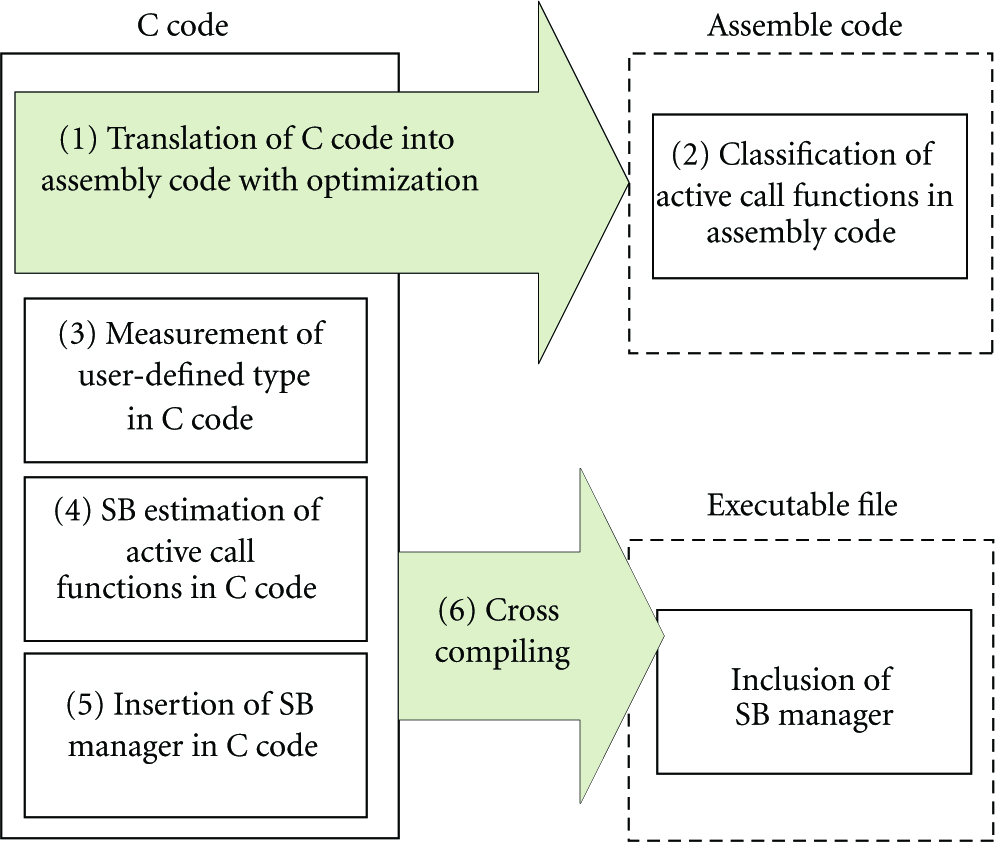
The procedure of code analysis.
3.4. SB Manager
The SB manager performs a series of procedures at inserted points at runtime. It assigns and releases memory blocks to/from an SB for a function or an ISR and maintains the information for the use of the blocks in the memory map. Since SBs of a caller and a callee can be located on separate areas in data memory, the SB manager provides the seamless movement of SP between the SBs.
3.4.1. SB Manager in Functions
Generally, an object file is created through compiling and linking phases, during which some code, referred to as compiler generated code (CGCode), is automatically inserted into several points of source code by the compiler. At runtime, CGCode conducts several tasks to provide a suitable context for the execution of each subroutine. When a function is called, CGCode commonly pushes SP to store argument variables and a return address and diverts PC to the entry of the called function. Then, CGCode pushes SP to secure a stack memory space for local variables of the function. Values of local variables are changed at the points where the local variables are declared with initialization values or are used, for example, int
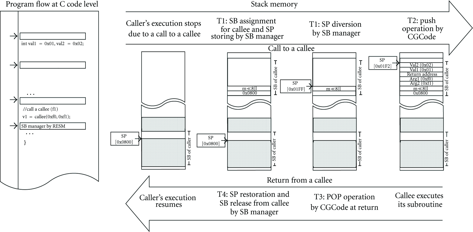
An example of stack operation in RESM.
Prior to allocating memory blocks to an SB at a function call, the SB manager searches for a set of contiguous empty blocks that can accommodate the SB. When the SB requires m blocks, the SB manager creates a bit string consisting of m bits,
3.4.2. SB Manager in ISRs
Once an interrupt occurs, PC jumps to the corresponding ISR and CGCode is executed to store the current context information in stack memory. In RESM, the context information is stored in the SB of a function or an ISR, which is currently executed. Then, the SB manager is invoked. It conducts a series of tasks involved in assigning memory blocks to the SB of the user-defined ISR. After the user-defined ISR is completely executed, the SB manager again intercepts the program flow to restore the value of SP and to release the SB. After the ISR returns, the context is reinstated at the point at which the interrupt event occurred by CGCode.
3.4.3. Function Call Deferring Algorithm (FDA)
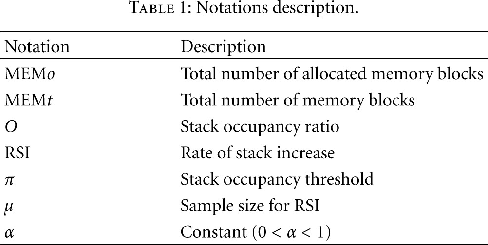
Firstly, we introduce some notations used in this section as shown in Table 1. At the entry or exit of a function call, the SB manager calculates MEMo, by increasing or decreasing the number of blocks allocated to the function call. At every context switching, it also calculates the variance of MEMo, by subtracting the current MEMo from the previous one. Then, RSI is calculated using a moving average of the latest μ variances. μ is set to the number of tasks currently executed, that is, the number of tasks in ready state or running state. Thus, RSI indicates an average stack usage of a running task in a scheduling interval during the latest execution time. During an execution time, μ tasks are alternately executed and consequently context switching occurs at μ times. μ ranges from 10 to 40. The negative value of RSI indicates that the stack usage is decreasing. On the other hand, the positive RSI means that the stack usage is increasing. At the entry of every function call, the SB manager executes FDA as shown in Algorithm 1.
Notations description.
(i) when a task try a function call which requires m memory blocks for SB O = MEMo/MEMt the function call is allowed (i) the function call is allowed
(i) the function call is allowed with a probability of ( (ii) the function call is denied with a probability of until the next execution cycle (i) the function call is denied and deferred until the next execution cycle
At the entry of a function call, FDA examines O and RSI to determine whether the state is stable or metastable. π is a configurable parameter. In our experiment, we set π to 0.7. If the function call requires allocating m blocks which do not cause the memory saturation, the function call is allowed. Otherwise, FDA for the metastable state is executed. In the metastable state, FDA evaluates RSI. If RSI indicates that the stack usage has decreased enough to accommodate the SB, the function call is allowed even in the metastable state (case A). Otherwise, the function call is probabilistically deferred with a probability of

An example of stack operation in RESM.
4. Performance Evaluation
In Section 4, we evaluate the performance of RESM with respect to space efficiency, overhead, and reliability from both numerical results and experimental results.
4.1. Scenario
Since there is no standard application on sensor networks, we define a scenario, in which the performance of RESM is evaluated and compared with that of the conventional fixed stack allocation method. The scenario assumes that a number of tasks run, simultaneously, and each task calls a recursive function, called as a virtual function. A virtual function do not any meaningful job but consumes resources such as CPU time and stack memory like a real function. The resource that a task consumes is adjustable by configuring four parameters; SB, p, t, and max. SB indicates the size of stack space that a virtual function needs for running without any stack overflow, p is the probability that the function recursively calls itself, t is the time consumed for the execution of the subroutine, and max is the maximum call depth by which the function is allowed to recursively call itself. Note that p is not O. The call depth, k, indicates the number that a running virtual function recursively calls itself at that time. Once a virtual function is called, it permanently runs. k of a virtual function can vary between 0 and max. We classify sensor tasks into two types according to the pattern of the stack use. The first is a general type, in which there is no pattern for the stack use. The general type represents non-event-driven tasks which run once or permanently. The second is an event type, in which the stack use of tasks shows a similar pattern. The event task is triggered according to events, for example, tasks for networking, monitoring, or surveillance applications. An event occurrence causes a task to process the event by calling a series of functions, whereas few functions are called when any event does not occur. Accordingly, the stack usage increases rapidly at an event occurrence and decreases sharply after the event processing is completed. Figure 7 shows the pseudocode of a virtual function for the general and the event types. In Figure 7, SB, t, p, and max are set to 30 B, 10 ms, 0.5, and 5, respectively. Then, the stack space that the task requires can vary between 50 B and 300 B according to k. A recursive call is made only if a randomly chosen value is within p. When k reaches zero, a virtual function does not return, though a randomly chosen value is within out of p. When k approaches max, k does not increase anymore, though a randomly chosen value is within p. Adjusting parameters, a task can show the various patterns for the stack memory use.

Pseudocode of virtual functions with
4.2. Analytical Modeling
Let 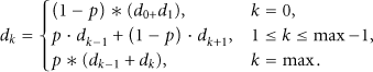

Markov chain model for the call depth.
Then, for each 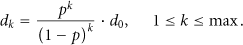
Using the fact that 
Similarly, 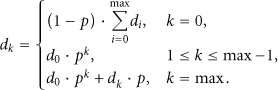
Then, 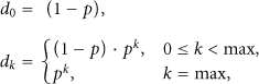

4.3. Reality versus Analytical Model
Figures 9 and 10 present the impact of varying p on the distribution of 

The distribution of
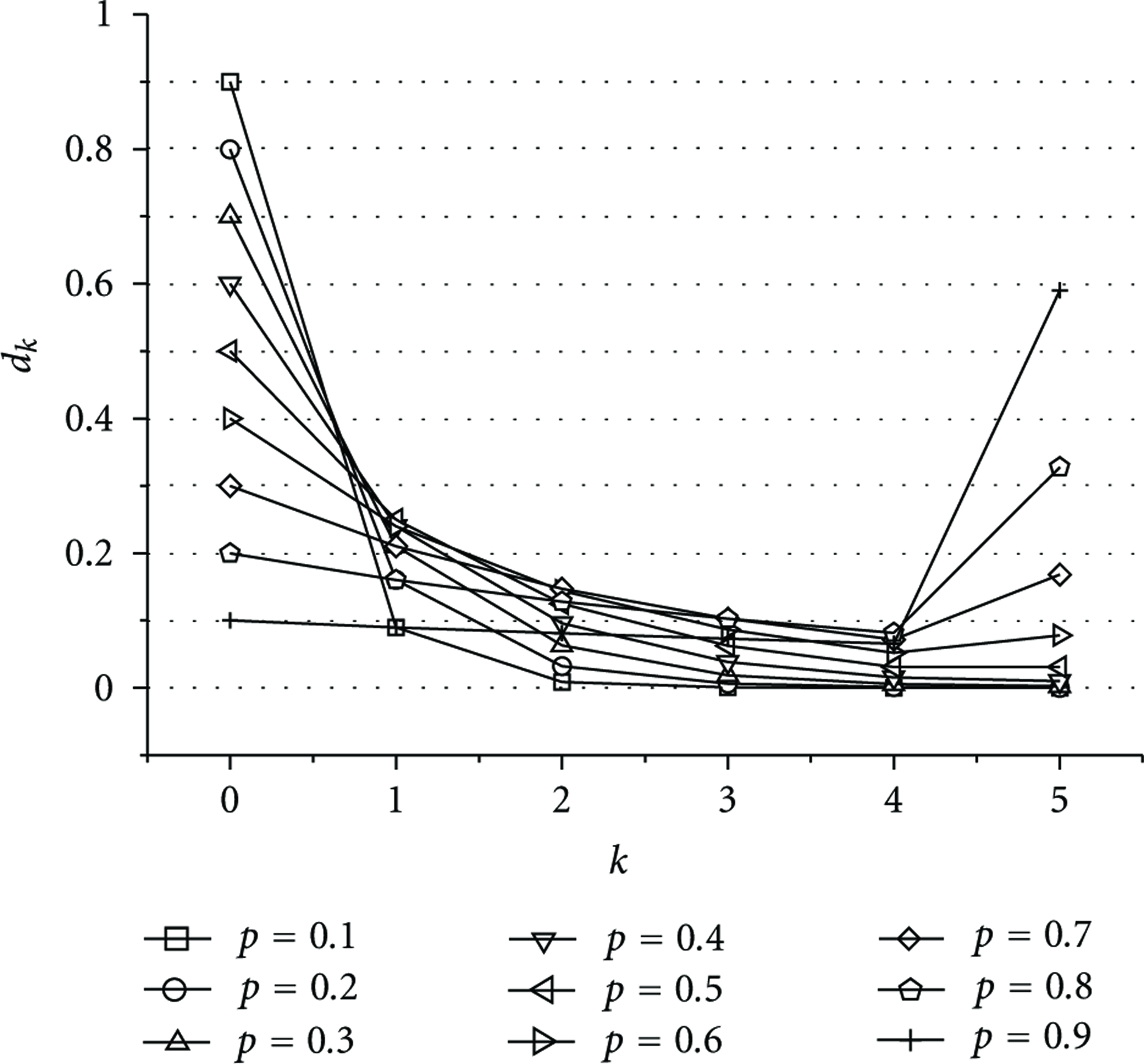
The distribution of

Experimental results for
From (11), the event ratio, λ, can be expressed as

Analytical results for
4.4. Memory Usage
In this section, we evaluate the expected stack usage and the memory overhead in RESM and OTL [24]. Figure 13 shows the impact of p on the probability,

The probability that a task approaches its maximum stack depth.
The expected stack memory usage of a task in RESM, 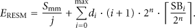

Equation (14) shows the expected stack memory usage of a task in OTL [24]. As mentioned in Section 2, OTL does not consider the space for the context information when estimating the stack space of a function. Similar to FSM, 
In this evaluation, j, SB, and max are configured as 10, 60 B, and 5, respectively. Then, n is obtained as 3 by using (3). In MSP430 5438, 20 B is required for

Expected stack memory usage per a task.
Assuming that virtual functions in all tasks have the same set of parameters, the capacity, C, in which the data memory can accommodate the maximum number of tasks can be estimated as
Expected task capacity.
4.5. Robustness
In this subsection, we evaluate the robustness of RESM under conditions of stack overflow on a real sensor node. In order to evaluate RESM on the real sensor node, RESM needs to operate on the multithreaded sensor OS such as MANTIS OS. However, most conventional OSs for WSN require the additional memory space and the additional computing time for their various subsidiary functions internally executed. Due to the additional functions, it is hard to measure the memory space or the computing time caused by RESM. To exactly evaluate the RESM, it is necessary to minimize functions in OSs. For the experiment, we developed a simple OS on a real sensor node. The OS consists of the multithreaded task scheduler and device drivers. The scheduler has one ready queue, into which user-defined tasks are sequentially inserted. Then, the scheduler periodically fetches and executes a task from the front of the ready queue at the interval of 10 ms. If a task is being executed at the end of the interval, the execution of the task is suspended and inserted into the rear of the ready queue, and, then, the newly fetched task is executed, that is, context switching. Fortunately, it is very simple to implement the context switching on such MCUs used on sensor nodes. The context switching includes pushing and popping SREG, general-purposed registers, and SP and manipulates SP and PC. Table 2 shows the parameters for the experiments.
Experiment environment.

To evaluate the robustness of RESM and OTL, we adjust the parameters to reproduce the memory saturation. 40 tasks are concurrently executed on the simple OS, and each task is assigned a unique task ID (TID) from 0 to 39. Each task executes its virtual function for the event type. The same parameters of
Figures 16 and 17 show the stack memory usage for all tasks in OTL and RESM during the execution cycles. From Figure 16, it is shown that deadlock occurs and the system halts as soon as the stack memory is saturated in OTL. In contrast, RESM avoids the saturated condition, and all tasks run without deadlock. Since RESM can detect the metastable state and prevent the memory saturation by using FDA at runtime, the total stack memory usage does not excess 16 KB. For visibility, Figures 18 and 19 show the stack usage for the total tasks, task 3 and task 30 from Figures 16 and 17. From Figure 19, the stack usage of tasks increases in a discrete manner since function calls are deferred by FDA. Accordingly, RESM can continue to execute all tasks without any stack memory fault even under the saturated condition at runtime. That is, under the saturated condition, RESM accommodates as many tasks as possible. Figure 20 shows the impact of p on the call deferring probability as the event ratio increases. Except for p, the experiment parameters are identically set to those of Figure 17. As the event ratio increases, tasks process more events, and then the stack usage increases. Accordingly, the call blocking rate increases due to the lack of memory. At

Stack operation under a saturated condition in OTL.

Stack operation under a saturated condition in RESM.

Deadlock problem in OTL.

Deadlock avoidance in RESM.

Function call blocking rate versus p.
Figure 21 shows the impact of p on the execution time and the delay time for a task. Numbers on bars present the delay ratio calculated as the proportion of the delay time to the execution time. The delay time and the execution time is the average on 40 tasks. The waiting time is measured as the sum of time that a task spends for the execution of FDA when a new function call is denied at the metastable state. The total execution time is measured as the sum of time during which a task preempts the MCU execution, that is, the time that a task spends in running state. Then, the execution time is obtained by subtracting the delay time from the total execution time. Note that the execution time includes the time that RESM consumes at successful function calls. Here, we are interested in time that a task spends waiting for deferred function calls in the metastable state. At

Execution time and delay time versus p.
4.6. Time Overhead
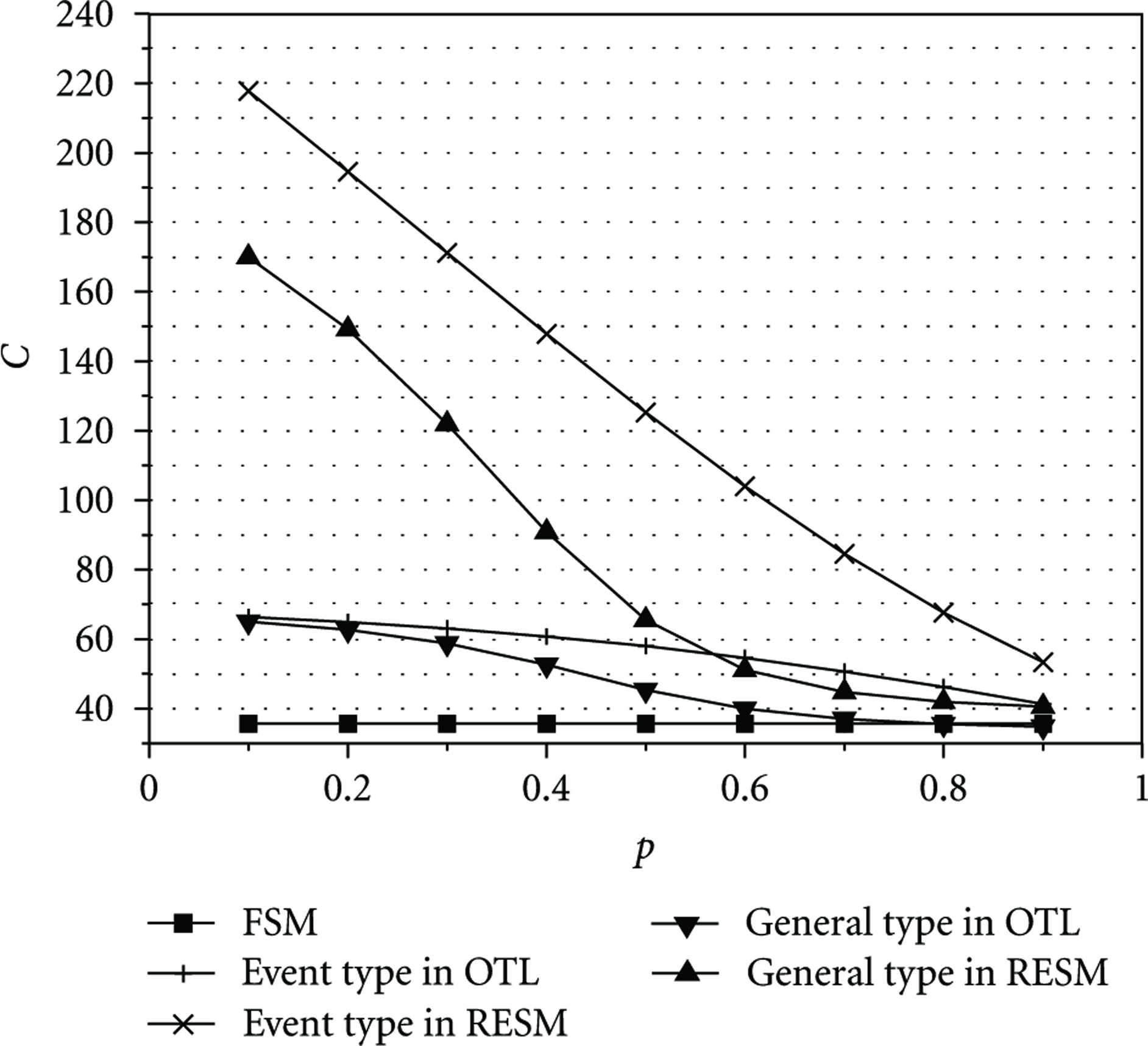
In this subsection, we experimentally measure the time overhead caused by RESM. First, the number of attempts on function calls is measured for all tasks. Then, the delay time is measured as the sum of time that RESM consumes. After that, the average consumed time per a successful function call is calculated as the delay time divided by the number of attempts. As shown in Figure 22, the average time consumed by RESM increases under a higher p. It can be shown that the function call deferring rate is zero at
Average time overhead per a successful function call in RESM.
5. Conclusion
In this paper, we propose a robust and space-efficient stack management method (RESM) for sensor OSs on sensor nodes with scarce H/W resources. RESM dynamically assigns memory blocks for an SB at each function call, and it releases the blocks at each function return. RESM keeps the total stack memory usage similar to the amounts that a system actually requires at runtime. To do this, we implement the code analyzer to estimate the stack memory amount for all active functions and ISRs and to modify the user code at the C code level, and the connection between stack spaces separated on memory is introduced. In addition, RESM provides a reliable execution environment to tasks. It anticipates the memory saturation by using FDA and conditionally allows function calls when the current memory state is unsafe from the memory saturation. From analytical and experimental results, it is proven that RESM provides the efficient stack usage and the robustness with the tolerable overhead.
Footnotes
Acknowledgment
This research was supported by the Agency for Defense Development (ADD), Republic of Korea, under the Dual Use Technology Program.