
Abstract
The objective of this paper is to investigate the influence of a hole curvature on the flow structure and characteristics downstream of JICF (jet in cross-Flow) by means of smoke visualization and particle image velocimetry (PIV). The experiment was performed in a low speed wind tunnel with Reynolds numbers of about 480 and 1000, based on the hole diameter and main flow speed. Two geometries were tested: a circular hole with 90° curvature and a circular straight hole for comparison, under blowing ratios 0.5 and 1.0. The measurements were done in the symmetric plane and four cross-sections. The results show that the curved hole could decrease the mixing behavior of jet flow with the main flow as the hole leading edge also increases the chance of transportingthecoolant to the wall surface and the transverse coverage. The curved hole shows a high potential to increase the cooling effectiveness once it is applied to the turbine blades.
1. Introduction
In order to raise the cycle efficiency, today's gas turbine is heading towards high pressure ratio and high turbine inlet temperature. Consequently, thermal and mechanical loads of the turbine components exposed to the hot gas will be increased, leading to the necessity of applying efficient cooling techniques in order to guarantee the lifetimes. One of the often used cooling techniques is film cooling, in which coolant air extracted from the compressor is transferred into the cava of turbine blades and then ejected out through discrete holes or slots, arranged in a certain way, around the blades into the blade flow passage. The air forms a thin and low temperature film covering the blade and/or endwall surfaces for protecting them from the hot main flow. Since the extraction of air from the compressor incurs a penalty to the thermal efficiency and the ejection of coolant air into the blade passage and its mixing with the hot gas as well, introduce additional energy losses, it is therefore necessary to get more insight into the local flow field and then find a way to optimize the cooling hole design.
The essential features of such film-cooling flow are present in a more generic flow situation of JICF. Extensive investigations on this fundamental flow field by experimental and numerical methods have been done for many years [1–7]. Margason [8] and many others had given a detailed summary on the earlier studies. A detailed review on the recent progress in the study of JICF can be found from Karagozian [9].
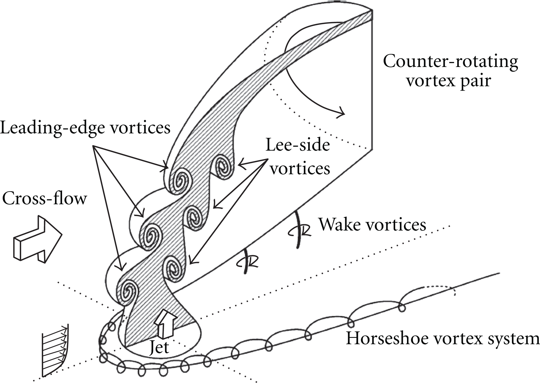
Interaction of the jet flow with the main cross-flow creates a localized, very complex large-scale vortex structure near a jet hole, as shown in Figures 1 and 2 from Fric and Roshko [6] and New et al. [10]. It is known that the near-field entrainment in the vicinity of the jet exit is influenced by these vortices [11], while the far-field entrainment is dominated by the CVP system [12].

Sketch of four types of vortices associated with the transverse jet near field (Fric and Roshko [6]).
Sketch of large-scale vortical structures nearby a cooling hole with the shaded region of the cross-section of the jet cutting along the jet centerline in the main flow direction (New et al. [10]).
In film cooling applications, one of the targets in JICF investigation is reducing the coolant jet penetration and making it as close adherence to the wall over a long distance as possible, which is of crucial importance for achieving higher effectiveness of film cooling. As the rotation sense of a CVP is such that it lifts the jet flow off the blade surface, a certain research work has been done to weaken the CVP. Haven and Kurosaka [13] introduced a vortex pair inside the jet hole passage, by installing two microvanes within the jet hole, which creates a vortex pair with a rotation sense opposite to the kidney vortices. Peterson and Plesniak [14] reported that interaction of in-hole vorticity created by turning of plenum flow direction could weaken the CVP, resulting in a lower trajectory and increased spanwise spreading. Kang [15] proposed another way to weaken the strength and scale of CVP by shaping the jet hole to create a secondary passage vortex pair (PVP) inside the jet hole. The PVP, rotating in the opposite sense to CVP, would be formed due to the centrifugal force acting on the low speed flow inside the boundary layer of hole a surface, as sketched in Figure 3. Stregth and scale of PVP will be increased with the hole curvature and boundary layer thickness. The PVP in curved channels was first observed by Dean, so that it is also named as Dean vortex pair characterized by the Dean number [16]. Liang et al. [17–19] made a further numerical investigation in a curved hole with a square and circular cross-section by RANS and DES methods and confirmed that the curved hole weakens the counter-rotating vortex pair. However, there are still issues which remained unclear in the detailed mechanisms, which request further experiment and numerical work. Hence, this paper is to investigate the influences of hole curvature on the characteristics and structure of the vortex flow downstream in the JICF with a curved hole by means of PIV apparatus. The film cooling application will be taken as a background in the analysis and discussions. In addition, the experimental results may form an additional reference and database for CFD validation.
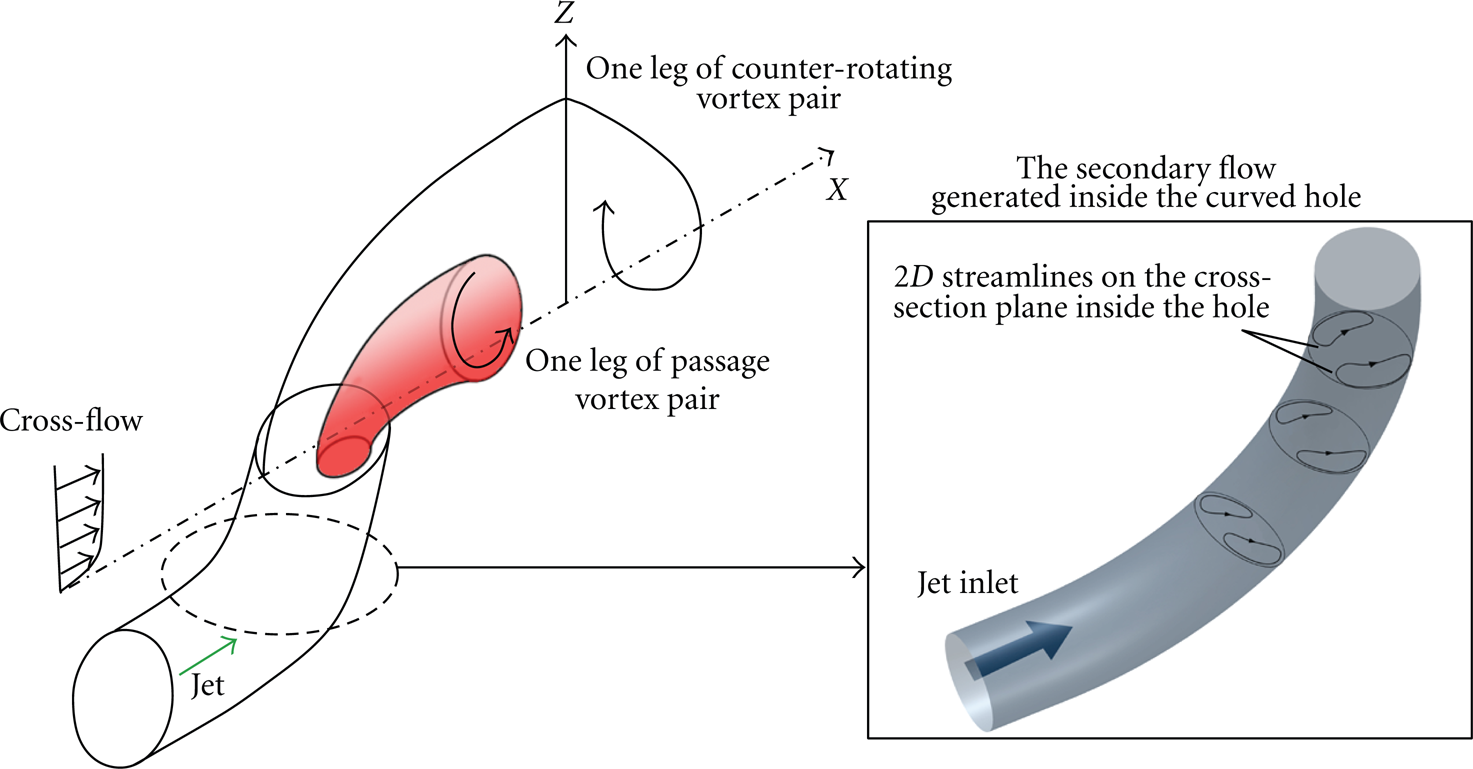
Sketch of main vortices nearby the curved hole exit.
2. Test Facility and Experimental Procedure
2.1. Test Rig
The experiments were performed in a low speed open-loop wind tunnel as sketched in Figure 4. The main flow is supplied by a centrifugal fan with a capacity of maximum total pressure rise of 2200 kPa. The test section is 1600 mm long with a cross-section of 700×400 mm2 (

Sketch of test rig.
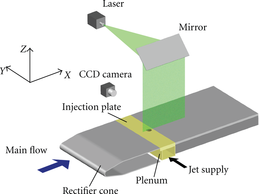
Sketch of test plate.
The light source is supplied by Nd:YAG laser from BIG SKY with the highest repetition rate of 20 Hz. The type of CCD camera is POWERVIEW Plus 4 MP from TSI with resolution of 2048×2048 pixel. The photo data captured by camera will be transported through a cable to PC. In order to get the time averaged results, 50–100 pairs of two-frame photo for one case were captured to quantify the flow field.
2.2. Hole Configuration
Two types of hole configurations, straight and curved with 90° curvature, as sketched in Figure 6, were investigated. Hole diameter D is 6 mm. The length of straight hole

Hole configuration.
2.3. Test Settings
The smoke was only seeded for jet fluids to visualize the jet; while in PIV measurements, the smoke was seeded both for jet and main flow fluids. Because of the limitation of the sampling frequency of the PIV apparatus used and safety of the camera placed at downstream of the wind tunnel outlet, the main flow velocity is set to 1.2 m/s and 2.5 m/s, which corresponds to Reynolds number Re
D
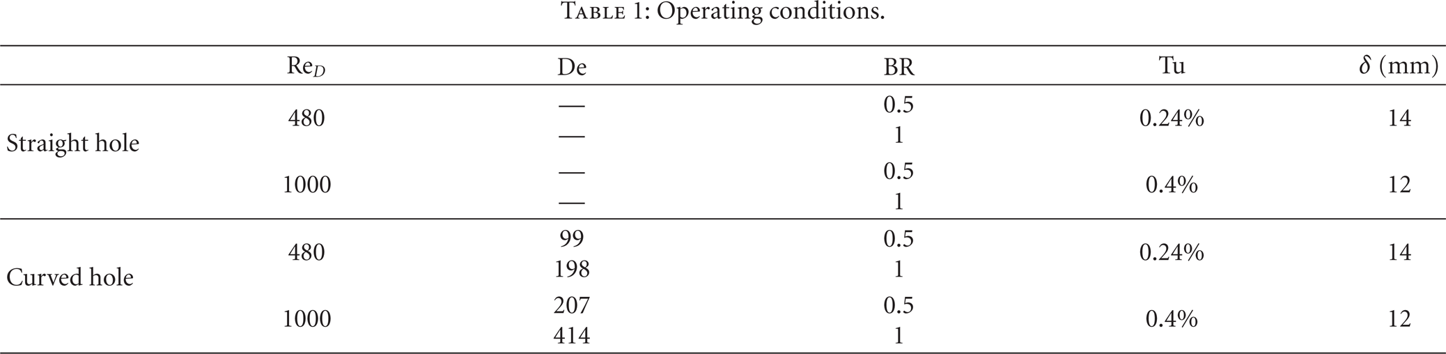
, based on the hole diameter and mainstream velocity, of about 480 and 1000. Velocity profile over the flat plate was measured at 393 mm downstream of the plate leading edge. Blowing ratios (BR), ranged from 0.5 and 1.5, were tested and they are defined as the ratios of the averaged jet speed against the main flow speed. However, discussions in this paper will be mainly focused on the results of BR 0.5 and 1.0 for both straight and curved holes. The measurements were done in the symmetric plane Y = 0 and four cross-sections
Operating conditions.
2.4. Experimental Uncertainties
The Kline-McClintock [21] method is applied to estimate the uncertainties of the measurements. In this way, the uncertainties of time averaged velocity can be decided with confidence of 95%. In the near-region downstream of the hole exit, the relative uncertainty of time averaged velocity is ranged from 6% to 15% under flow condition of Re
D
= 1000,
3. Results and Discussions
3.1. Symmetric Plane
3.1.1. Instantaneous Visualization
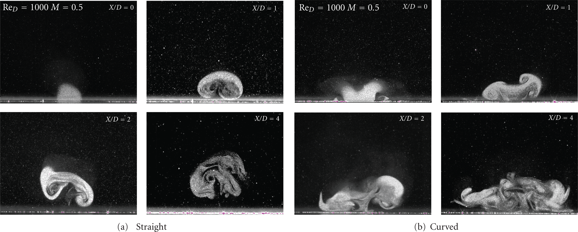
Figures 7 and 8 are instantaneous visualization pictures in the symmetric plane under

Instantaneous smoke visualizations in symmetric plane for straight hole configurations under

Instantaneous smoke visualizations in symmetric plane for curved hole configurations under
The shear-layer vortices viewed in the symmetric plane corresponds to the cut-off view of the hairpin vortices as shown in Figure 9 which presents a snapshot of the coherent structure of Q isosurface obtained with the DES method by Liang and Kang [19] under blowing ratio 0.5 and Reynolds number 4000 for straight and 90° curved holes. The Q is defined as


Instantaneous Q iso-surface for straight and 90° curved holes,
It is seen from Figure 9(a) that when a hairpin vortex is well formed and shaded downstream, a next hairpin vortex starts to be formed in series. These results may suggest that the development of hairpin vortices is the underlying mechanism of coolant liftup. For the curved hole as shown in Figure 9(b), the PVP (or Dean vortex pair) issued from the curved hole exit could be clearly observed and it has a great influence on the formation and evolution of the hairpin vortices. The hairpin downstream was skewed and weakened due to the interaction of PVP with shear layer vortices, so the liftup of jet fluids would be suppressed and then increase the cooling effectiveness.
A horseshoe vortex is seen upstream of the jet in Figure 9 which could not be resolved by the experimental visualization. Streamwise vorticity component of the hairpin vortices will form the CVP which is evolving in a periodic unsteady manner with intermittent vortex structures as viewed from DES results. The wake vortices in Figures 7 and 8 extend upright from the wall towards the trajectory, which could be the normal vorticity component of the hairpin vortices. The wake vortices allow fluid to be drawn from the boundary layer into the jet itself, with an efficient entrainment of the boundary layer fluid into the downstream and the wake region of the jet, as indicated by Fric and Roshko [6].
The shear-layer vortices with coherent counter-rotating vortex pairs, named as wind-ward vortices and lee-ward vortices observed by New et al. [10] along the trajectory for blowing ratios from 2.3 to 5.8 for straight hole could not be observed from Figures 7 and 8 for blowing ratios 0.5 and 1.0. However, this vortex structure could be clearly observed under higher blowing ratio in this study as shown in Figure 10 which presents an instantaneous smoke visualization in the symmetric plane for a straight hole under blowing ratio 1.3 and Reynolds number 240. In Figure 10 a chain of vortex pairs with coherent counter-rotating wind-ward vortices and lee-ward vortices is observed.

Instantaneous smoke visualizations of straight hole in symmetric plane under blowing ratio of 1.3.
It was believed that the curved hole could weaken the streamwise vorticity due to the secondary vortex pair, generated by the hole curvature, which is rotating in the opposite sense with CVP. As one can observe by comparing the height of the trajectory from the wall is reduced by the curved hole configuration under all the blowing ratios and Reynolds numbers. The number of the hairpin vortex under the same flow conditions is reduced by the curved hole, such as from 7 to 4 by comparing Figures 7(a) and 8(a). Even the less visible vortex structure could be observed at the higher Reynolds number condition in Figures 8(c) and 8(d). The jet flow breaks up in a short distance into small scale vortices. These behaviors could enhance the transportation of jet fluids towards the wall surface and lead to greater adherence.
Besides, care should be taken in concluding the vortex structure presented in Figures 7 to 10. Since they are instantaneous visualizations, the structure observed may be strongly associated with the time when a snapshot is taken. Hence, discussions on the time-averaged parameter are necessary which are given below.
3.1.2. Time-Averaged Presentation
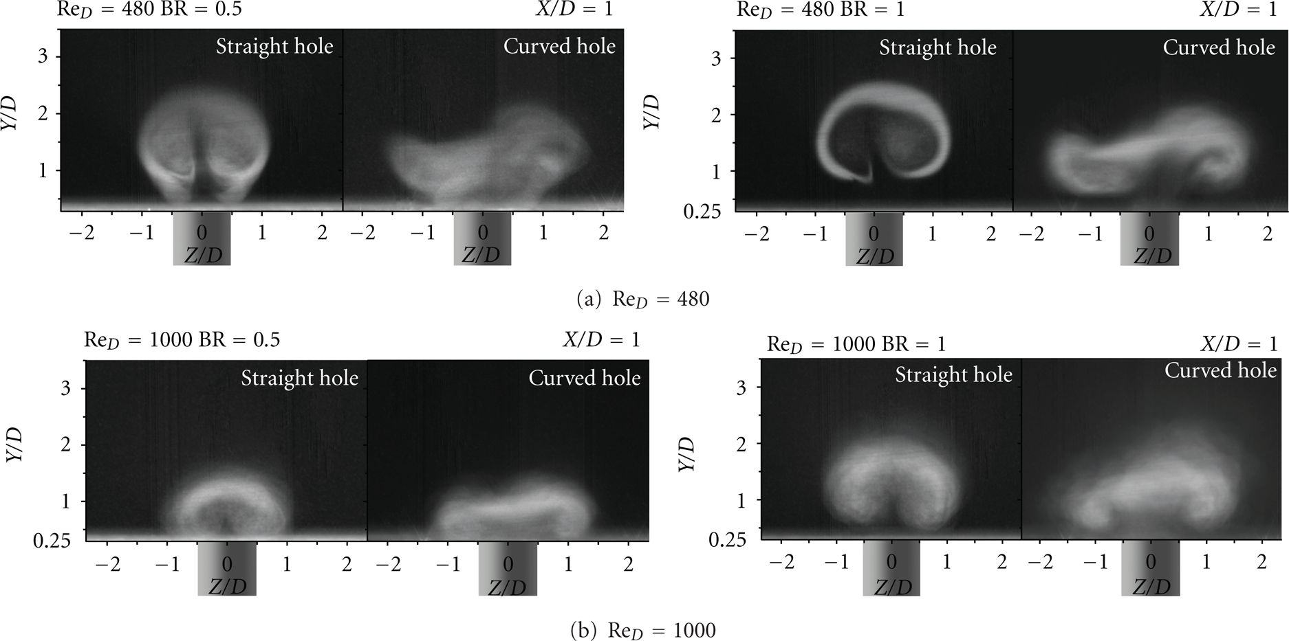
All the time-averaged quantities to be presented hereafter are obtained over 50 to 100 sequential shots, with the sampling frequency 7.24 Hz, of the PIV measurement results. Figures 11–13 show time-averaged smoke photography, contours of the time averaged velocity magnitude Vmag and vorticity ω
y
, in the symmetric plane for both holes under blowing ratios of 0.5 and 1.0 for Reynolds number 1000. It is seen from Figure 11 that, instead of the obviously observed vortices in the instantaneous smoke visualizations (Figures 7 and 8), jet smoke fluid in white is diffused along the main flow direction without visible vortices. A dark area close to the wall downstream of the jet exit is clearly observed in the pictures for straight hole cases but not for the curved hole cases. This indicates that the jet fluids issued from the curved hole could well adhere to the wall surface and could definitely improve the cooling effectiveness. It is seen from Figure 12, velocity contour with vectors, that the coming boundary layer flow is disturbed by the jet flow. Thickness of the boundary layer downstream the hole exit increases with the mainstream due to the motion of CVP and the blowing ratio. Compared to the straight hole cases, the thickness is reduced in the curved hole cases due to the passage vortex pair, generated in the curved hole passage, with an opposite rotation sense to the CVP. Location of maximum velocity near the hole exit deviates from the hole center towards the main flow direction due to the shearing action of cross-flow. It can be observed that the maximum velocity near the jet exit is increased with blowing ratio and reduced in the curved hole case, which can also be seen from Figure 13. Figure 13 shows the normal velocity component V
z
profile, extracted from Figure 12, at the location of
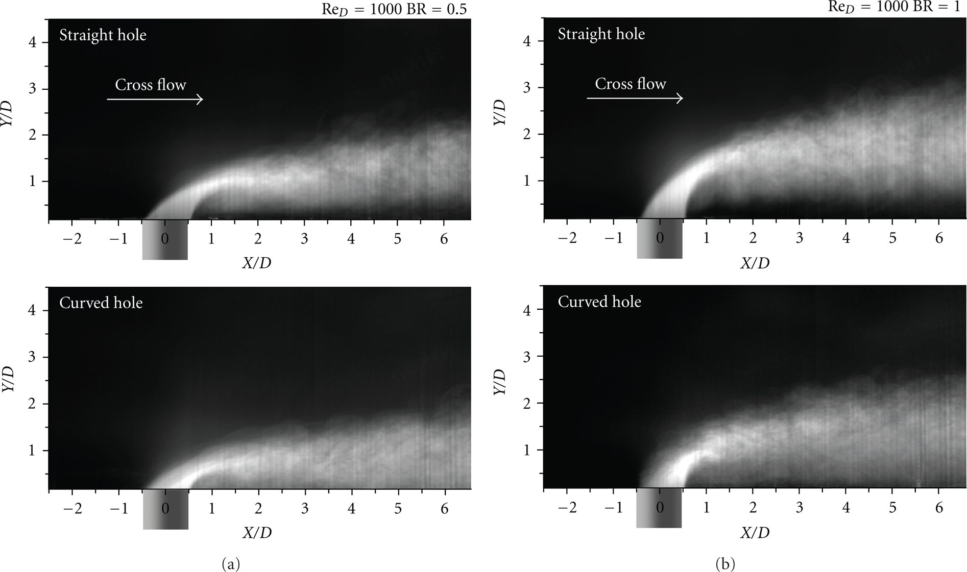
Time averaged smoke visualizations in symmetric plane, Re
D
= 1000 and
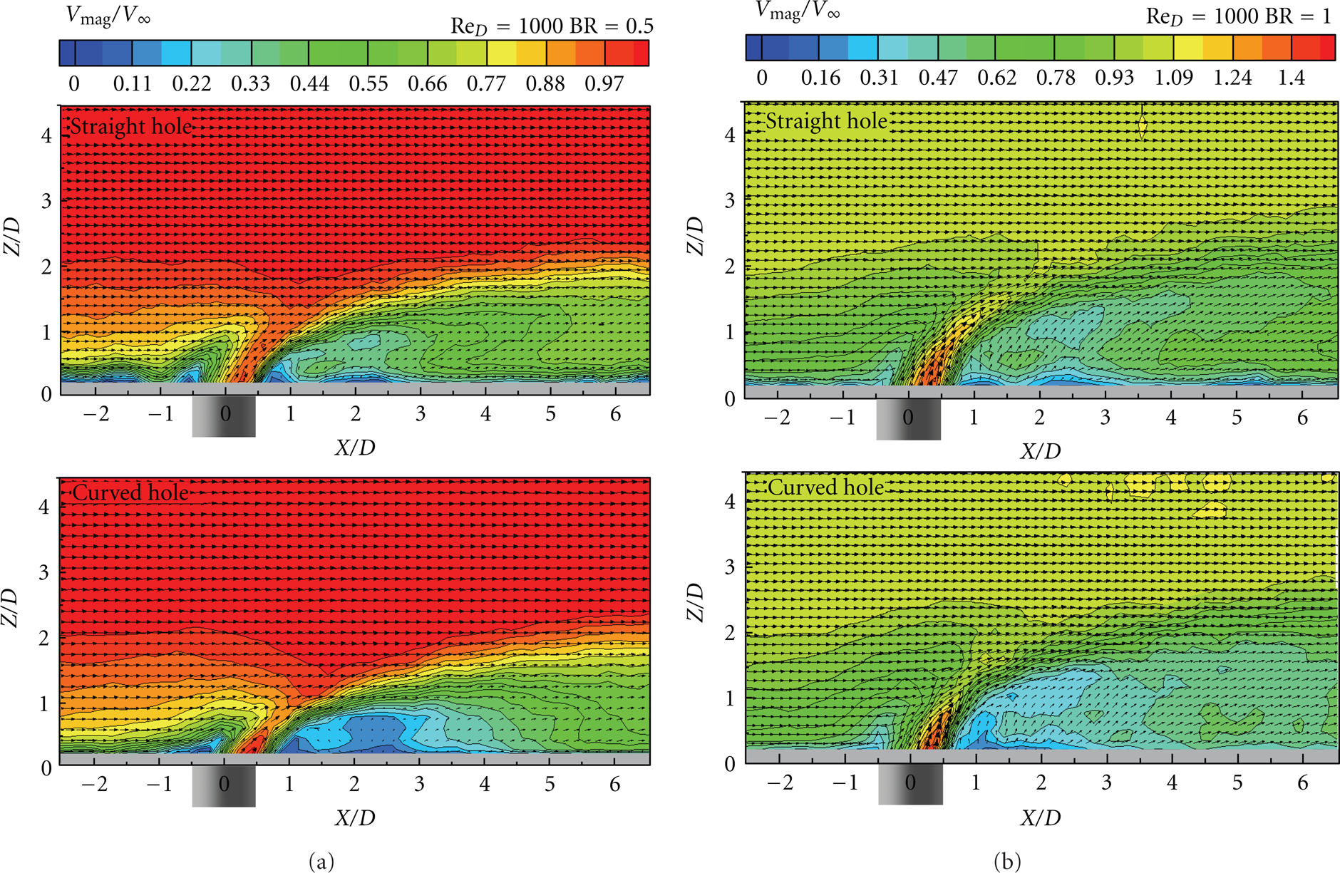
Time averaged velocity in symmetric plane for both holes at Re
D
= 1000 and

Profiles of normal velocity component V
z
near hole exit center in symmetric plane,
Figure 14 shows the contours of time averaged vorticity ω y in the symmetric plane, with positive vorticity turning in the counter clockwise. It is seen that vorticity near the wall for both holes is negative, associated with the boundary layer, except for a small range, a short distance downstream of the hole exit under blowing ratio of 0.5. Along the jet trajectory, vorticity is positive at the wind-ward side and negative at the lee-ward side. The value of the vorticity increases with blowing ratio for both straight and curved holes and reduces from the straight hole to the curved hole for the same blowing ratio, which is consistent with the velocity profiles in Figure 14. It can be seen that the wind-ward side vorticity cannot be maintained as far as the lee-ward vorticity towards downstream, which is consistent with the instantaneous smoke visualization observations in Figures 7 and 8 in which only vortices in clockwise could be clearly visible along the trajectory. Zones, with positive vorticity, located between the wall and the jet trajectory may indicate the wake vortisity.

Time averaged vorticity ω
y
in symmetric plane, Re
D
= 1000 and
3.2. Cross-Sections
In order to further understand the jet flow structure in its cross sections, the smoke is again seeded only in the jet fluid and four cross sections
3.2.1. Instantaneous Visualization
Figures 15 and 16 present the instantaneous visualization pictures of the jet flow in the four cross sections for straight and curved holes, respectively, at Reynolds number Re
D
= 480 and blowing ratios of 0.5 and 1.0. Scale of the space occupied by each of the pictures and their resolution are the same. It is seen that the jet flow is expanding in both vertical and transverse directions with distance towards downstream from
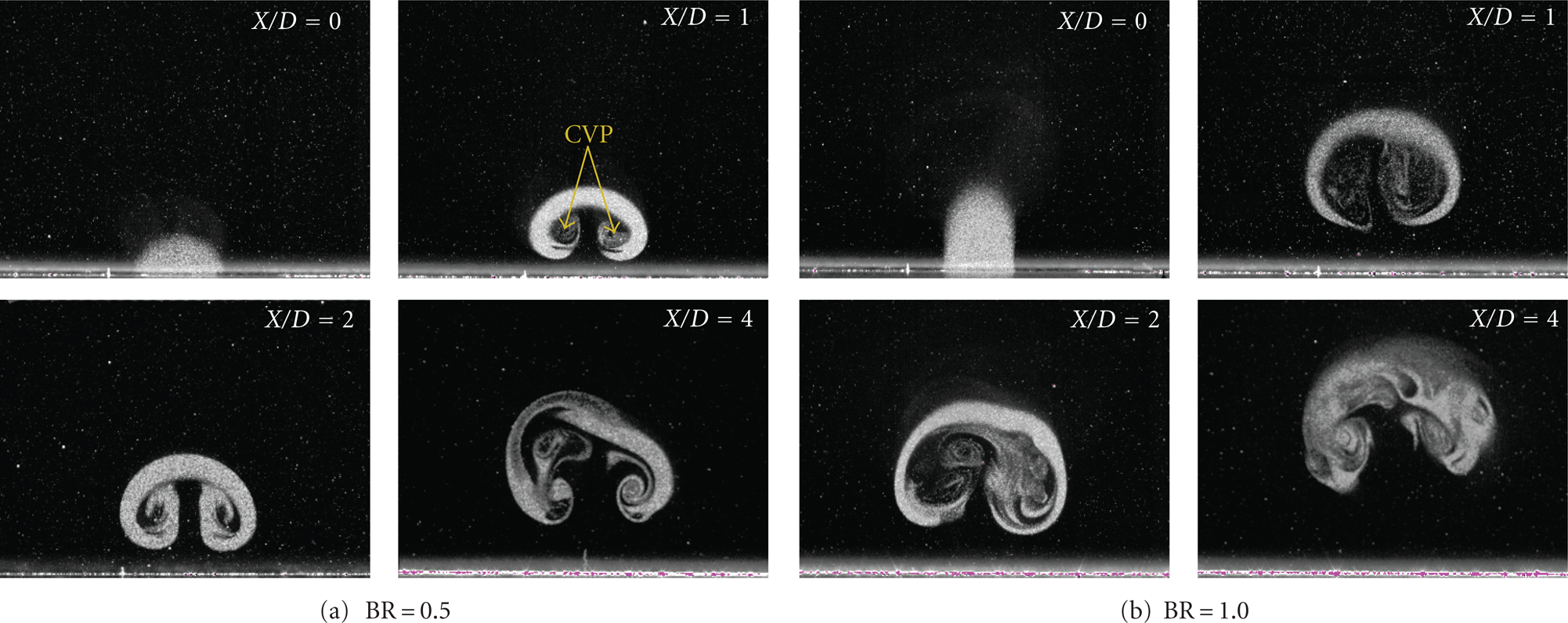
Instantaneous smoke visualizations of jet flow in four streamwise sections for straight hole at Re
D
= 480, (a)
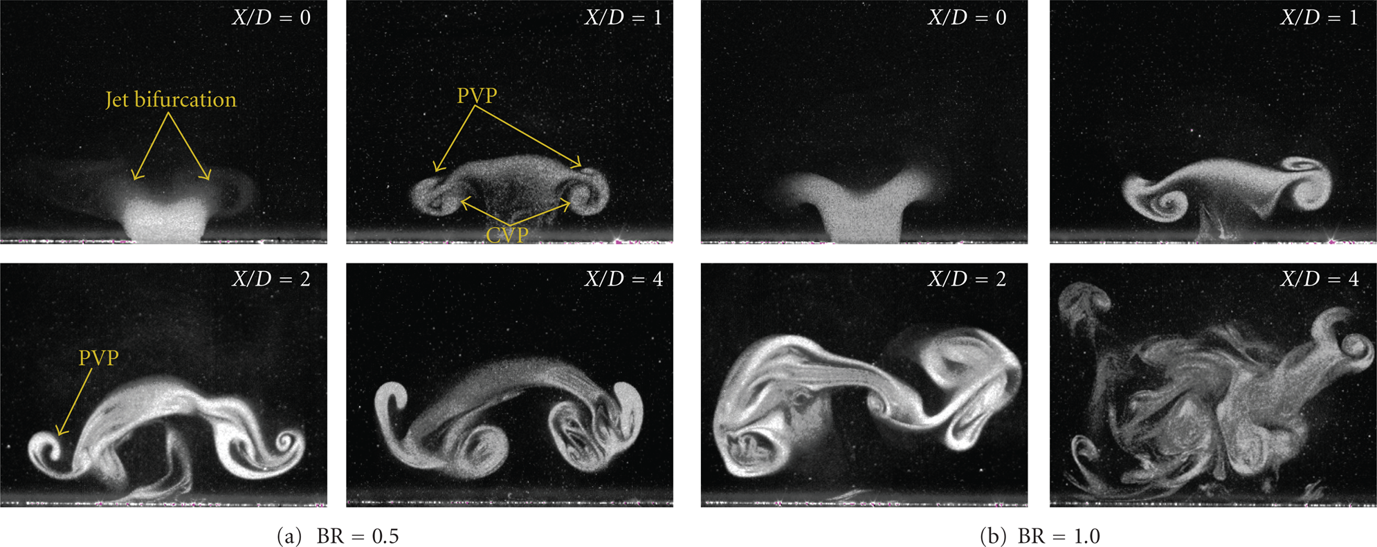
Instantaneous smoke visualizations of jet flow in four streamwise sections for curved hole at Re
D
= 480, (a)
It is observed from Figure 16 (curved hole) that the structure of the jet flow is totally different from that in Figure 15 (straight hole) and exhibits completely different flow characteristics, caused from the passage vortex pair (PVP) generated by the curved hole passage. Interaction between PVP and CVP leads to form a new vortex structure, as observed, which is distinct from the kidney shaped vortex structure in the straight hole cases. At section
With increasing Reynolds number, the instantaneous smoke visualization pictures show highly unstable and less well-organized vortex structure for all the blowing ratios and hole geometries studied, especially for the curved hole cases, as one can see from Figure 17. Figure 17 shows the instantaneous smoke visualization pictures in the four sections of both straight and curved holes under
Instantaneous smoke visualizations of jet flow in four streamwise sections at Re
D
= 1000 and
3.2.2. Time-Averaged Presentation
Figure 18 is the time-averaged smoke visualization pictures for both hole in the section of
Time averaged smoke visualizations in the section
In order to further understand the evolution of PVP and CVP and their interaction along the jet trajectory, contours of time averaged vorticity ω
x
in the four sections
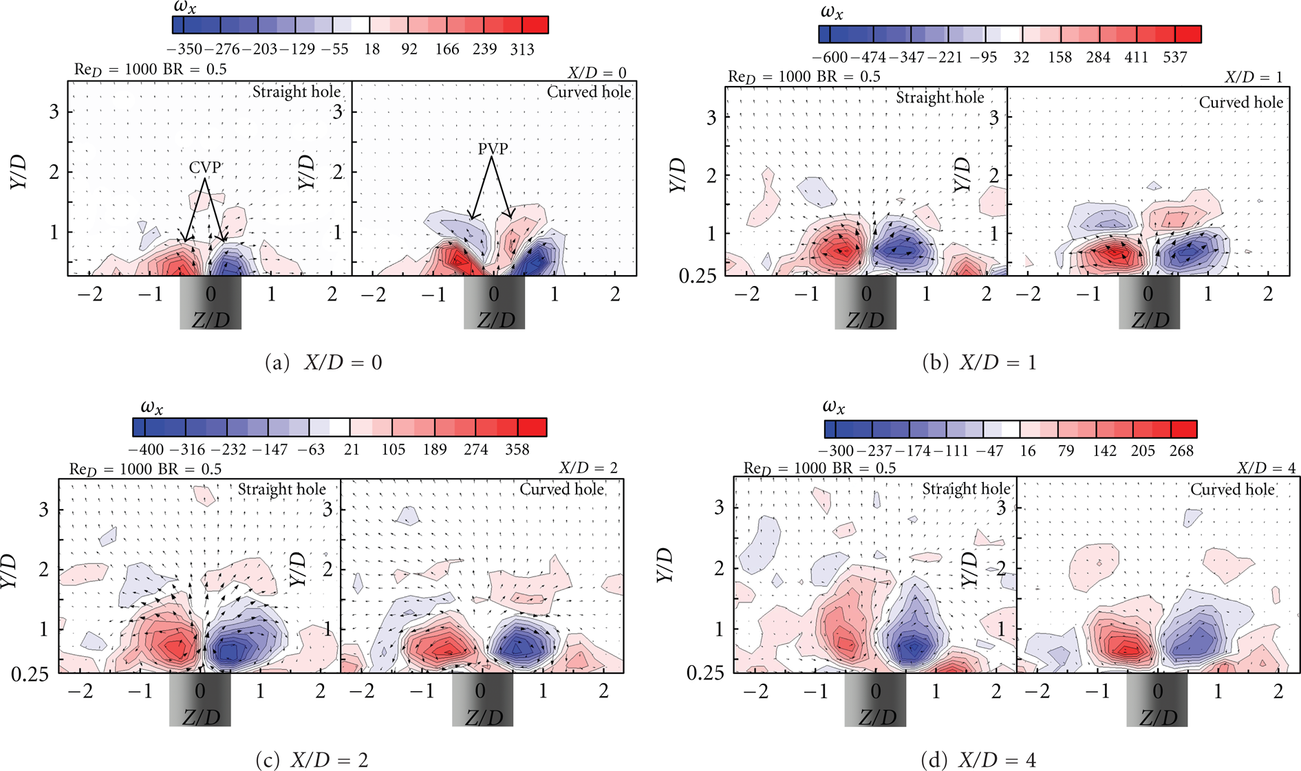
Contours of time averaged vorticity ω
x
in four cross sections, Re
D
= 1000 and
Figure 20 shows the variation of CVP center height (Y/D), read from time-averaged section streamline patterns of one vortex due to its symmetry, with streamsiwe sections. As expected, the height is increasing with distance for all the conditions studied. Increasing blowing ratio and/or reducing of the Reynolds number will result in the increase of Y/D for both holes. It may be noticed that high Reynolds numbers correspond to low boundary layer thickness or displacement thickness. It then may be concluded that the evolution of CVP center height in the mainstream direction is affected not only by the blowing ratios but also the boundary layer thickness. It can also be seen again that the height of the curved hole is lower for all the flow conditions than that of straight holes.
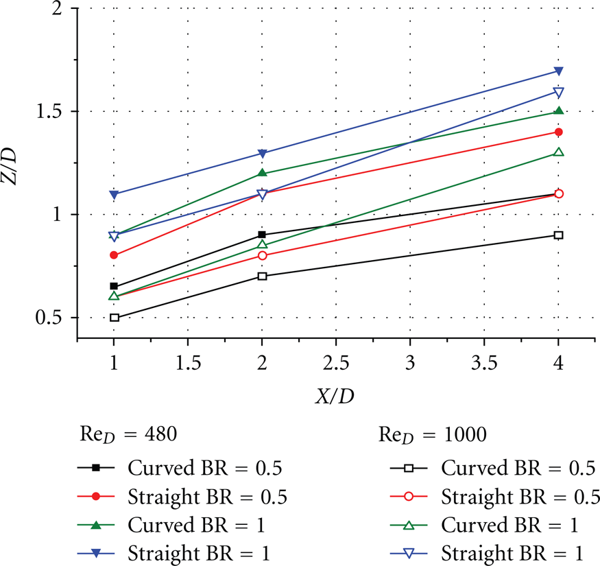
Variation of CVP center in wall normal direction along streamwise direction, read from the time-averaged section streamline patterns.
4. Conclusions
The flow structure downstream of jet in cross-flow has been investigated by means of PIV. Instantaneous and time-averaged visualization pictures and quantities in the symmetric plane and four cross-sections are presented and discussed for different Reynolds numbers and blowing ratios, with the comparison of curved hole to straight hole.
The flow leaves the jet upwards to a certain distance from its exit without visible vortex motion and then turns towards the mainstream direction with a series of hairpin vortices along the jet trajectory and a wake vortex system under the trajectory. Height of the trajectory reduces with increasing Reynolds number and decreasing the blowing ratio. With increasing Reynolds number, the smoke traces become more unstable and disordered and break up into small scale vortices in a short distance downstream of the jet exit for all the blowing ratios and hole geometries studied, especially for the curved hole cases.
The PVP generated inside the curved hole rotating in a sense opposite to CVP downstream. PVP could weaken CVP due the interaction between them and enhance the transportation of jet fluids towards the wall surface and lead to greater adherence of the jet fluid to the wall in all conditions studied. The curved hole configuration shows its high potential in the film cooling applications.
Footnotes
Acknowledgment
The authors would like to acknowledge the financial support received from the National Natural Science Fundamental of China.