
Abstract
A wheelchair with a lifting function is designed to assist a caregiver when transferring a wheelchair user not only indoors but also outdoors. The target user is typically a severely disabled person with disabled upper and lower limbs and therefore needs the physical support when using a toilet or transferring from a bed to a wheelchair and so forth. Both the wheelchair and the lift are driven by their respective motors. The user can approach above the toilet stool or the bed from the rear because the large driving wheels are located in front of the body, and the seat can be folded. This wheelchair is allowed to travel on public roads because of the mechanism of folding the frame for lifting. This paper presents the concept design and the experimental results of a full-sized prototype wheelchair with the lifting function, which confirms the design effectiveness.
1. Introduction
Persons with disabilities attributable to the lower limbs are becoming increasingly numerous worldwide. In Japan, they number about 3,480,000 (severely disabled persons were about 760,000) in 2006 [1]. Most of them use wheelchairs in daily life. Representative nursing care in daily life entails basing, evacuating, and feeding. Transfer when basing, evacuating, and other processes cause back pain to caregivers [2, 3]. Matsumoto and Kusunose reported that 77% of caregivers and 64% of nurses have back pain [4]. Consequently, various devices and robots have been developed. Imado et al. developed a simple supporter for reducing lower back exertion when lifting a person using rubber tubes [5]. Molift Inc. developed the “Quick Raiser 2,” which lifts a user with a linear actuator and supports the standing up and seating motions [6]. Koyama et al., Satoh et al., and Yamamoto et al. proposed some exoskeleton-type power-assisted systems using electric motors and air actuators [3, 7, 8]. Bostelman et al. developed a robot system that a user himself wears and enables him to use a toilet, a bed, and so forth [9]. A caregiver robot “RI-MAN” developed at RIKEN is aimed at realizing autonomous motion transfer [10]. Some of those tools and robots are, however, expensive and are limited for use in indoor environments.
For patients whose mobility is limited, a patient lift (Hoyer Lift) is commonly used indoors during transfer between a bed and a chair or other similar resting place. We take notice of a transfer tool that can be used even when going away. Similar to some commercial transfer products, “LikoLight” is a foldable mobile lift [11], and “Komawari-san” is a simple tool based on lever principles [12]. These tools, however, are too large and heavy to carry over long distances. “RODEM” is a new type of electric wheelchair on which the user can ride from the backside and which can run outdoors, but the target is limited to mild patients [13].
This paper presents a wheelchair with a lifting function that is intended mainly for use by an electric wheelchair user with disabled upper and lower limbs. This equipment has good maneuverability. Moreover, it can move over a step because of the front driving wheels. It realizes easy and safe transfer from/to a bed and a toilet stool by virtue of the opposite wheel allocation of a usual wheelchair. Furthermore, the mechanism of folding the frame for lifting allows this wheelchair to travel on public roads. We demonstrate its design effectiveness through several indoor and outdoor experiments.
2. Conceptual Design
We assume a single caregiver for the use of this wheelchair. It helps alleviate the burden of the caregiver when a disabled person moves between the wheelchair and toilet/bed easily and safely. Figure 1 presents the conceptual design of the wheelchair and its features. We presuppose that the target users for this equipment will be able to take a seating position (e.g., in the case of spinal cord injury, the level is milder than C6).
The wheelchair has a lifting function. The lifting mechanism comprises a lifting frame, a sling seat, and a winch such as a conventional lift (see Figure 1(a)). The winch is driven by an electric motor that a caregiver operates using an up/down switch. This winch is not back-drivable because a worm gear and a worm wheel are used in it. Therefore, this design is safe: the previous state remains even if the power source is cut off. A toileting sling is used for this equipment. Therefore the user can wear it in a seated position and take off underclothes in the lifting position.
Large driving wheels are located in front of the body, and the seat can be folded. Therefore, the user can approach above a toilet stool and a bed from the rear. As a result, this equipment can lift a user easily and safely. Furthermore, this location: front driving wheels are rigid and rear wheels are casters, has good maneuverability resembling that of a forklift truck.

Wheelchair with a lifting function.
The user can travel outdoors, even on public roads, because a driving unit for an electric wheelchair is used for this equipment, and it has a mechanism of folding the frame for lifting (see Figure 1(c)).
3. Usage of the Equipment
In this section, we address the usage of the equipment for two representative transfer motions: a bed and a toilet.
3.1. Transfer from a Bed to the Equipment
The sequence of transfer from a bed to the equipment is the following. The alphabet characters of each item given below correspond to those of the panel in Figure 2.
The equipment with its seat, backrest, and armrest folded is moved near a user, who is seated on a bed.
The sling seat that the user is wearing is hooked up to the lifting cord. Then the user is lifted by winding the lifting cord.
The user goes forward and is lifted from the bed. The caregiver lightly touches the user to prevent the body from swinging.
After expanding the backrest, armrest, and seat, the user sits on the seat. The user can unfasten or take off the lifting cord.
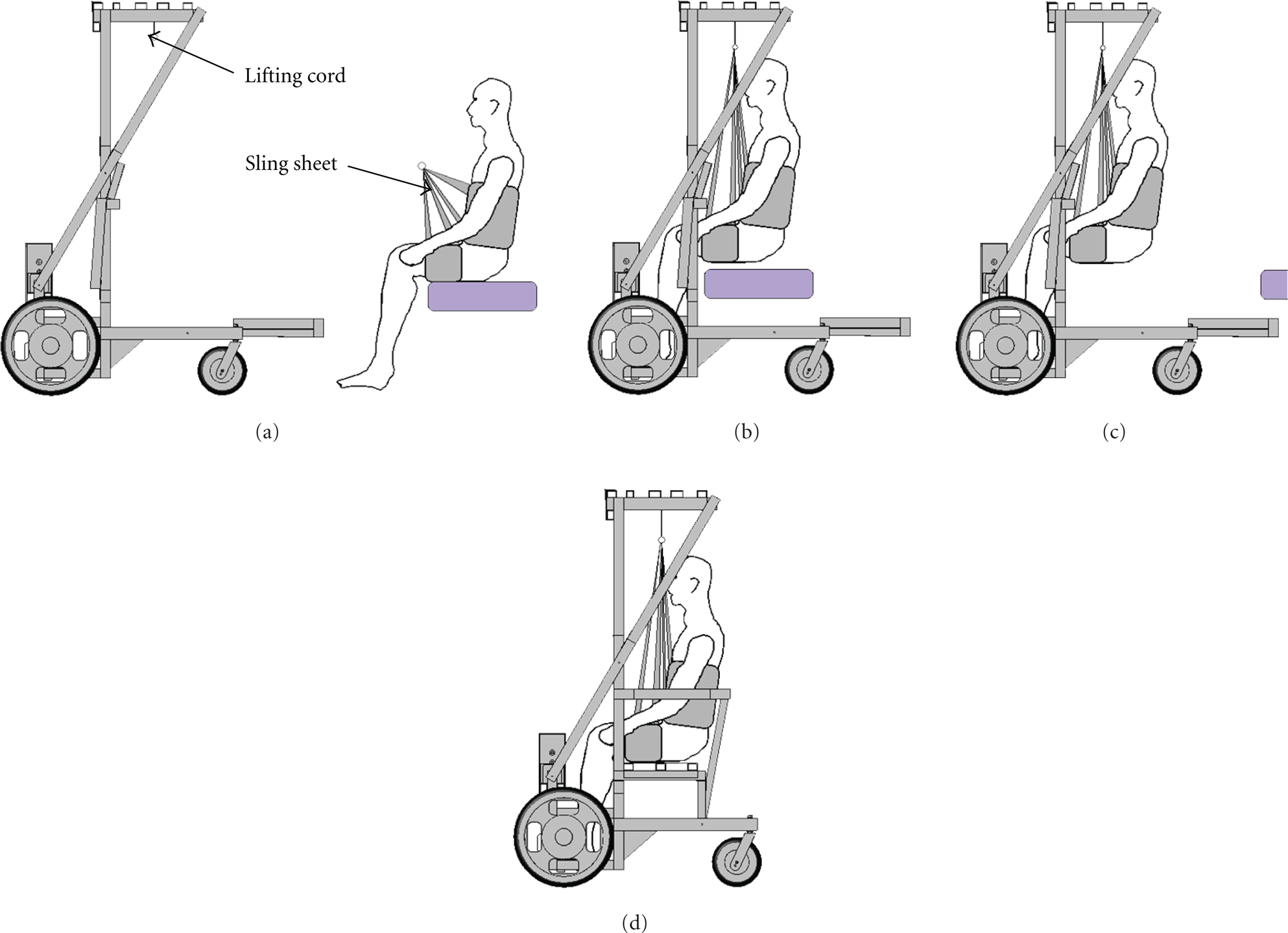
Procedure when transferring from a bed.
3.2. Transfer from the Equipment to a Toilet
The sequence of transfer from the equipment to a toilet is the following. The alphabet characters of each item given below correspond to those of the panel in Figure 3.
Expand the lift if it is folded.
Attach the sling seat to the lifting cord and lift the user by winding the lifting cord. Then remove the seat and fold the seat frame. Here it is not necessary to fold the armrest and backrest because the width between the rear frames is wider than that of the toilet stool (see Figure 12(c)).
Take off the user's underwear with the user lifting. Then the user moves backward and moves above the toilet stool.
The user moves downward slowly and sits down on the toilet stool.

Procedure when transferring to a toilet.
4. Analyses of Strength and Stability
4.1. Analysis of the Strength
The strength of the equipment is analyzed using finite element method with COSMOSWorks, which is add-in software of 3D-CAD software SolidWorks. The conditions of the analysis are the following.
The user weight is 150 kg. Vertical loads are taken to the lifting frame or the seat frame.
Aluminum alloy (A6063, yield stress = 145 N/mm2) is referred.
The following results were obtained through these analyses.
The maximum stress is 54.8 N/mm2 at the lifting frame when lifting, which is 51.9 N/mm2 at the rear frame when seating. Both values are under the yield stress of the aluminum alloy (145 N/mm2).
The maximum displacement is 4.00 mm at the lifting frame when lifting, which is 0.79 mm at the rear frame when seating.
The safety ratio is 2.15 FOS when lifting, which is 2.04 FOS when seating. The results are portrayed in Figures 4(a) and 4(b). Here, the minimum value is shown in each circle.

Analysis of the strength.
Through those results, we confirmed that this model has sufficient strength as a prototype model. A 2 mm thick hollow square aluminum bar is assumed for these analyses referring to the commercial product. However, we must reconsider the material, shape, and thickness when producing commercial equipment.
4.2. Analysis of the Stability
The equipment stability during transfer is discussed in this subsection. We discuss two cases because the user is lifted vertically in a stationary state; then the user moves to a target point in horizontal direction. We analyze the former and latter cases, respectively, using the stability margin and zero moment point (ZMP).
Figure 5 shows the model during expansion. Here, x1 and

Model for analysis of falling.
The calculated position of COG of the equipment when carrying a subject (166 cm and 65 kg), considering the weights of the equipment and the subject, is nearly at the top of his thigh (
Next, we discuss stability during travel. The safety acceleration against falling a
i

where M represents the total mass of the user and the equipment and g signifies acceleration of gravity. The position of the rear caster to the rotation axis changes according to the traveling direction,
Next, we described that the fear of falling is related to the acceleration and deceleration. Nagata and Koda examine the fear during transfer using a ceiling lift [14]. Results show that the acceleration of 0.24 m/s2 is the moderate value for humans and that humans feel too much danger if the acceleration is greater than 0.42 m/s2. Comparing those values with calculated accelerations (
5. Hardware
Figure 6 shows the appearance of the hardware. The size in expansion is
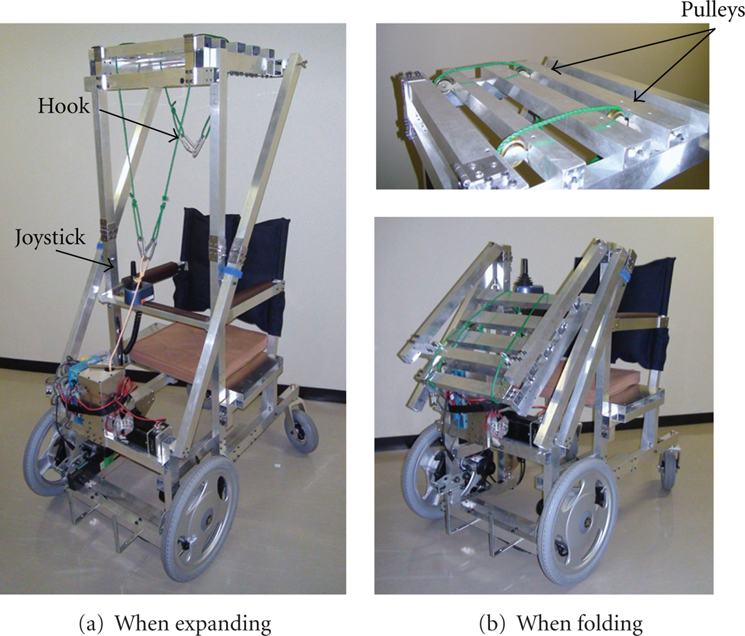
Full-sized prototype of a wheelchair with a lifting function.
5.1. Lifting Mechanism
Figure 7 shows the winch gearbox of the lifting mechanism that comprises a DC motor (250 W, RE75; Maxon Precision Motors Inc.), a winding rod, spur gears, a worm gear, and a worm wheel. The worm gear and the worm wheel make this winch non-back-drivable. Therefore, the user is safe even if the power source is cut off. The lifting cord connected to the winding rod is split into two parts and passes on pulleys that are attached to the lifting frame. A hook is attached to each end of the lifting cord. Two hooks connect the lifting cord to the sling seat.
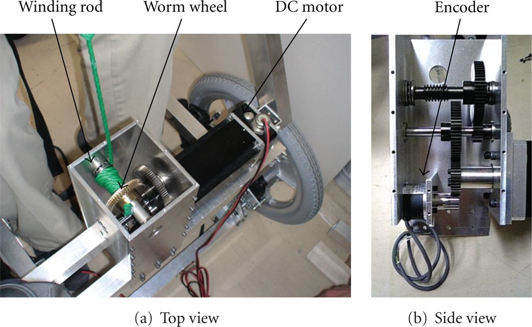
Gearbox of the lifting mechanism.
Output torque of 44.2 Nm is necessary to lift a 100 kg load. The maximum torque of the winch (its reduction ratio = 1/257) is 95.6 Nm (transmission efficiencies of the spur gears and worm gears = 0.98% and 0.5%, resp.). The maximum lifting rate is designed to be 10 mm/s.
We used a V55 CPU board (16 MHz; Japan System Design Corp.) and two batteries (WP2.6–12; Kung Long Batteries Industrial Co., Ltd.) for the lifting mechanism, which was controlled based on PD control theory. The sampling time was 20 ms. The caregiver operates up/down motions of the lift using a triple-pole switch. An encoder installed in the gearbox measures the height of the lift and functions as a stopper. A sling seat “Active Micro Plus (M size; V. Guldmann A/S)” was used for this equipment.
5.2. Wheel Mechanism
This equipment has large driving wheels in the front, which are the parts of a commercial electric driving unit used for wheelchairs (8.2 km/1-charge, forward: 2.5 km/h and 4.5 km/h, backward: 2.0 km/h, approximately 17 kg including a battery, Joy Unit; Yamaha Corp.). This equipment has casters for electric wheelchairs (ABSOLEX, diameter = 20 cm; Araya Industrial Co., Ltd.) for travel outdoors. The casters generate less vibration when traveling on bumpy roads with a built-in suspension.
5.3. Folding Mechanism
This equipment has folding mechanisms in the following parts: the lifting frame, the backrest and armrest frames, and the seat frame. First, Figure 8 presents the procedure that is used when folding the lifting frame.
The diagonal frame is freed when wing bolt (i) in Figure 8 is removed; then it is folded forward after snap lock (ii) is unlocked.
The lifting frame is folded forward.
The lifting frame is folded forward again after snap lock (iii) is unlocked.
The folding procedure is complete.
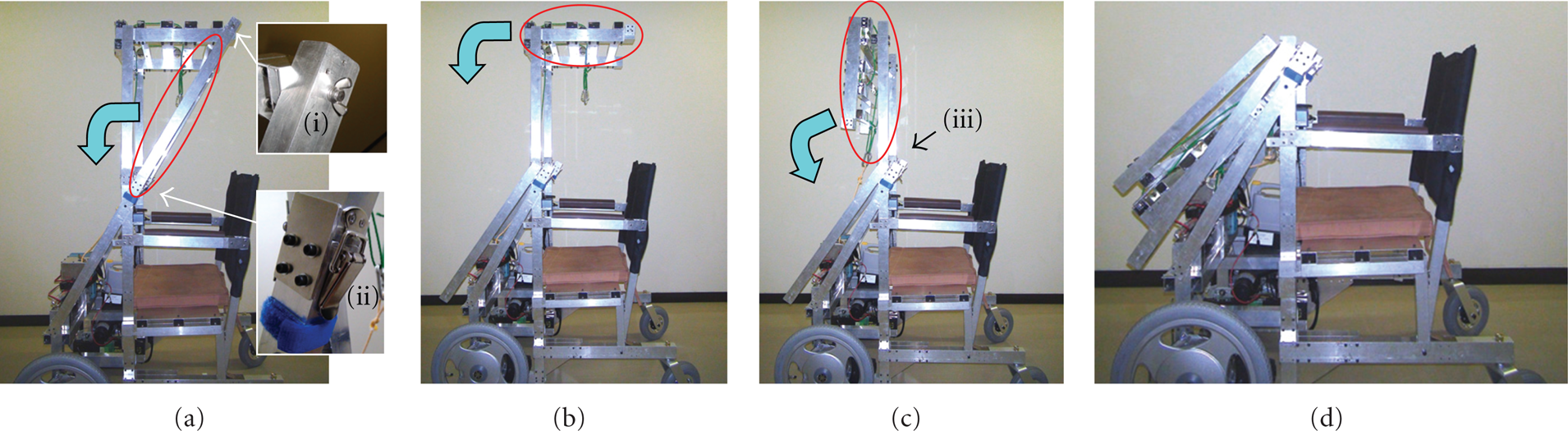
Procedure when folding the lifting frame.
The total time necessary for this procedure was about 40 s, which can be shortened by exchanging the wing bolt (i) for a pin.
Figure 9 shows the procedure that is followed when folding the seat frame, the backrest, and the armrest frame. The backrest frame is connected to the seat frame. They can be folded as desired. The backrest is cloth enclosing a cotton cushion.
Remove the seat and put it aside in a hook in front of the equipment. Then the seat frame is lifted upward and fastened to the diagonal frame by Velcro tape (see Figure 9(b)).
Pull out the backrest frame from the seat frame, and put it aside in a hook in front of the equipment.
Take of a wing bolt (iv) in Figure 9(c), and fold the armrest frame backward (see Figure 9(c)).
The folding procedure is thereby completed.

Procedure when folding the backrest and armrest frames.
The total time of this procedure, which was about 30 s, will be shortened using a pin instead of the wing bolt. Operations (c)-(d) are necessary for transfer to a bed. However, they can be omitted during transfer to a toilet stool (see Figure 12).
6. Experiments
We next address two basic operations: traveling and transfer experiments. The subject was a man (166 cm height, 65 kg weight) with no leg motion impairment.
6.1. Traveling Experiments
First, we confirmed the motions of traveling forward and backward and for turning in indoor environments. The user operated the equipment using a joystick in the same way as that used for a commercial electric wheelchair. Consequently, we noted that the user was not required to lean the joystick when turning because the driving wheels were arranged in front of the body.
We examined the steering performance of the equipment when passing through a door whose frontage size was about 80 cm. We confirmed that the arrangement of forward driving wheels as a forklift truck had better maneuverability than that of backward driving wheels as a normal electric wheelchair. The turning radius of the former is about 40 cm whereas that of the latter is about 86 cm. We also confirmed that it was possible to ride an elevator.
Finally, Figure 10 shows results of the outdoor examination. Figure 10(a) presents results obtained when ascending a 5 cm step. It was possible to go up/down the step because of the front driving wheels, although it is difficult for a conventional electric wheelchair to go up about 3 cm step. Figure 10(b) presents results obtained when traveling on a field. We confirmed that the equipment had sufficient ability to travel outdoors.

Snapshots of the traveling experiments.
6.2. Transfer Experiments
We examined the lifting motions. The results are presented in Figure 11; Figures 11(a) and 11(b), respectively, portray the time responses of the lifting height and velocity. Here, the lifting velocity was calculated from the difference of the lifting height measured by an encoder installed in the winch. The motion is operated manually using an up/down switch. The lifting mechanism was controlled with trapezoidal speed profile, with target acceleration of 2.5 cm/s2 and target maximum velocity of 1 cm/s. The directing maximum lifting velocity was about one-third of that of commercial lifts considering the clearance about 20 cm from the lifting frame to the head of the user. Accuracy of better than approximately 0.3 cm for the lifting height and approximately 0.04 cm/s for the lifting velocity at 25 s was obtained. The error of the lifting height was approximately 0.01 cm after 30 s. Those results show that this winch can follow the target trajectory. The trapezoidal speed controller realized smooth up/down motions, and the subject was lifted stably.

Experimental results of lifting.
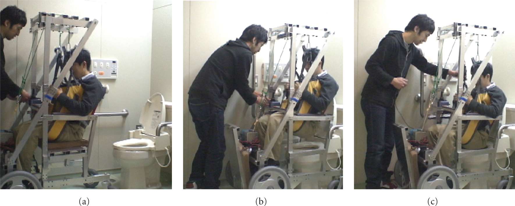
Snapshots when transferring to a toilet.
Figure 12 depicts the experimentally obtained result obtained for transfer to a toilet stool in a toilet for physically handicapped persons. The toilet stool height was 45.6 cm. The toilet stool width was about 20 cm, although the minimum width between the rear frames of the equipment is 37 cm. We confirmed that the subject was able to approach above the toilet stool from the rear. Each motion for a series of processes was the following, with the initial position of the equipment as 60 cm in front of the toilet stool.
0–21 s: the lifting cord was lowered; it was attached to the sling seat.
21–41 s: the subject was lifted; then the seat was removed, and the seat frame was folded (see Figure 12(a)).
41–56 s: the caregiver touched the subject to prevent swinging. The subject traveled backward approximately 60 cm (see Figure 12(b)).
56–83 s: the lift was lowered. The subject was seated on the toilet stool. Then the sling seat was detached from the lifting cord (see Figure 12(c)).
The height of the lift from the (a) position was 16.5 cm in the position of (b) and
7. Conclusions
We proposed a novel wheelchair with a lifting function for an electric wheelchair user with disabled upper and lower limbs. This equipment facilitates easy and safe transfer from/to a bed and a toilet stool by virtue of the opposite allocation of wheels from that for a usual wheelchair. Furthermore, the mechanism of frame folding for lifting allows this wheelchair to be used on public roads. Results show that this equipment had good maneuverability like a forklift truck. We also demonstrated that the equipment had sufficient ability of moving up/down a 5 cm step and of traveling on a field. It can be used in an actual toilet.
We presupposed that the target users for this equipment will be able to take a seating position. The proposed equipment can lift a person who is lying on a bed. However, the practical use of it for the user will be difficult because of the seating conditions and use of the toilet.
In future works, we plan to improve this system for better practical use, mechanical strength, and design. We are planning to add a headrest to the backrest frame. Better seating, safety, and comfort will also be required. We intend to produce this system to have a similar price to that of an electric wheelchair that has some additional functions, such as a reclining function. In addition, we are considering a manual winch to reduce costs and pricing.