
Abstract
Network coding (NC) can be applied to achieve the maximal information flow in a network. In energy-constraint wireless networks such as wireless sensor networks, applying NC can further reduce the number of wireless transmissions and hence prolong the life time of sensor nodes. Although applying NC in wireless networks is obviously beneficial, it is possible that a malicious node (Byzantine attacker) can take advantage of the inherent vulnerability of error propagation in the NC scheme to corrupt all the information transmissions. In the NC scheme, an intermediate node linearly combines several incoming messages as its outgoing messages. Thus a data error injected in any intermediate nodes will corrupt the information reaching a destination. Recent research efforts have shown that NC can be combined with classical error control codes and cryptography for secure communications or misbehavior detections. Nevertheless, when it comes to Byzantine attacks, these results have limited effects. In this paper, a distributed algorithm is developed to effectively detect, locate, and isolate the Byzantine attackers in a wireless ad hoc network with random linear network coding (RLNC). To the best of our knowledge, our work is the first to address the problem of Byzantine failures in a wireless network with RLNC.
1. Introduction
1.1. Network Coding
Network coding has become a paradigm shift in information transmission, it is first brought up by Ahlswede et al. [1]. Instead of traditional information transmission method, simply storing and forwarding, network coding allows intermediate nodes to mix received information together and transmit new information generated by the received information in terms of encoding. Due to encoding operation at intermediate nodes, data can be regarded as information flowing through a network, which is a sense of data compression. Therefore, throughput and bandwidth efficiency can be increased and delay can be decreased via network coding. In [1], it has showed that network capacity with network coding can be bounded by min-cut max-flow theory, which is larger than traditional storing-and-forwarding method.
1.2. Random Linear Network Coding
Recent research proving throughput gain of network coding in a variety of application makes network coding an attractive topic. With algebraic approaches, such as [2], a communication pattern with network coding of a network can be designed and achieve its promised capacity, which is the min-cut from the source to the sinks in a network graph [1]. However, the requirement of global topology information and the adoption of centralized optimization make algebraic approaches difficult to implement [3]. Therefore, a distributed network coding scheme, named random linear network coding (RLNC) was proposed [4]. RLNC is a powerful tool to disseminate information in networks for it is distributed and robust against dynamic topology. Without knowing global information such as network topology, RLNC regards every encoded packet as a coding vector over a finite field
1.3. Security Issue of Network Coding
Network coding shows its variety of possibilities and benefit in information dissemination; however, it also introduces a new type of security issue. The most serious security challenges posed by network coding thus come from various types of Byzantine attacks, especially packet-modifying attack. In particular, RLNC has been very robust to packet losses induced by node misbehavior [5]. Nevertheless, when it comes to packet-modifying attack, RLNC has become quite vulnerable. In RLNC, one intermediate node will linearly combine received packets and generate new packets to next multiple receivers. If this node has been compromised and generates error packets, other nodes receiving those error packets will also be modified for those error packets will stay in buffer and keep being combined with normal packets. Hence, nodes on a path that these error packets go through would become new compromised nodes without self-awareness and disseminate more error packets. In other word, the error due to modified packets will propagate in network with RLNC. Eventually, the whole communication network may be crushed just because of one single adversary node. Figure 1 shows how a single adversary node propagates error.

Error propagation due to modifying packets by Byzantine nodes in a network with RLNC.
The paper is organized as follows: Section 2 illustrates pros and cons of related works on Byzantine attacks, Section 3 describes our model and algorithm, Section 4 gives the simulation results and analysis, and Section 5 shows mathematical analysis. Section 6 concludes the paper with a summary of the results and discussion of further work.
2. Related Work
Existing method mostly modifies the format of coded packet against Byzantine attacks and can be divided into two main categories: (1) misbehavior detection and (2) end-to-end error correction.
2.1. Misbehavior Detection
Misbehavior detection applies error control technique or information-theoretic frameworks of encryptography to detect the modification introduced by Byzantine attackers. By types of nodes who take care of coding burden, misbehavior detection can be further divided into generation-based and packet based. Generation based detection takes similar advantage as error-correcting codes and lays expensive computation tasks on destination nodes. As long as enough information is retrieved by destinations, modification can be detected. Reference [6] proposes an information-theoretic approach for detecting Byzantine modification in networks employing RLNC. Each exogenous source packet is augmented with a flexible number of hash symbols that are obtained as a polynomial function of the data symbol. This approach depends only on the adversary not knowing the random coefficient of all other packets received by the sink nodes when designing its adversarial packets. The hash schemes can be used without the need of secret key distribution but the use of block code forces an priori decision on the coding rate. Moreover, the main disadvantage of generation-based detection schemes is that only nodes with enough packets from a generation are able to detect modifications and thus, result in large end-to-end delays.
On the contrary to generation-based detection schemes, packet-based detection schemes allow intermediate nodes in the network detecting modified data on the fly and drop modified packets instead of only relying on destinations, which is more suitable for high attack probability compared to generation-based detection schemes. Packet-based detection schemes require active participation of intermediate nodes with the ability to compute hash function or generate signature based on homomorphic hash functions [7, 8]. Hash of a coded packet can be easily derived from the hashes of previously encoded packets; in that way, intermediate nodes can verify validity of encoded packets before linearly combining them. This characteristic also prevents from error propagating in network. Unfortunately, homomorphic hash function is also computationally expensive and cannot be used in intersession network coding scenario while different sources combine their own source information together.
2.2. End-to-End Error Correction
End-to-end error correction schemes include error-correcting code method into the process of encoding packets and sinks can correct error and recover original information under certain amount of error. Like generation-based detection schemes, end-to-end error correction schemes lay all encoding and decoding tasks on sources and sinks, such that intermediate nodes are not required to change their mode of operation. The transmission mode for end-to-end error correction schemes with network coding can be described by matrix channel
Even though end-to-end error correcting schemes can recover original information at sinks, it cannot stop error from propagating and introducing large overhead (in worst case, only
3. Network Model and Byzantine Attackers
3.1. Network Model with RLNC
Consider a wireless network of n nodes with communication range of r randomly distributed in a square area, represented by an undirected graph
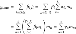
In the communication pattern in which we are interested, each node can perform RLNC to disseminate messages. One source S trying to multicast k messages


The practical format of transmitted packets.
3.2. Threat Model and Our Algorithm
We propose an algorithm, Distributed Hierarchical Adversary Identification and Quarantine, to fight against packet-modifying attack introduced by compromised Byzantine nodes. Assume
As mentioned above, network coding is susceptible to the packet-modifying attacks for errors will propagate by operation of linear combinations. However, our algorithm, DHAIQ, uses this characteristic to let error propagate within a certain range in order to let some chosen nodes, referred as watchdogs, detect that there are some Byzantine nodes in the monitored area. Before starting our algorithm, we assume that node density and its being known by every nodes from operating other algorithm such as aggregate computation. DHAIQ can mainly be divided into 5 steps.
When a network is under packet-modifying attacks, an arbitrary node in the network will trigger the whole algorithm. This node is the watchdog of the 1st level. This first watchdog will awake the 2nd level's four watchdogs and pass two messages, which are node density and the monitoring area size. The node density is a criterion of termination scheme and the whole deployment area is the 2nd level's monitoring range as Figure 3(a) illustrates. The awaken watchdogs are chosen by locations. These four watchdogs are situated in each corner of their common monitoring area. After awaking the 2nd level's watchdogs, the first watchdog ends its monitoring mode and turns back to its normal mode. Each of the 2nd level's watchdogs will generate its own special packet, referred as probe packet. It then sends this probe packet to the other three watchdogs in an area-restricted flooding way as described in Figure 3(b). Except for these watchdogs, every node that receives these packets will do encoding and then sends new packets to all its neighbors. These packets will be linearly combined via intermediate nodes and constrained to disseminate within the monitoring range. This is all determined at the 2nd level. There are four watchdogs and obviously four different probe packets which are in the same generation. The packets belonging to the same generation will start and terminate transmitting simultaneously based on a time stamp. Any node that receives the probe packets the first time will record this time stamp. Nodes will continue encoding and sending out packets until the time stamp is expired. If a probe packet reaches a node outside the monitoring range, this node will drop that packet. The information carried by probe packets only traverse in the monitoring range. With the time stamp, all nodes that belong to the same monitoring area can terminate transmitting simultaneously. Before the termination of monitoring, all watchdogs keep retrieving packets from other nodes and keep a packet pool in their buffer. An arriving packet is called innovative packet only if it is linear independent to each packets stored in a watchdog's buffer. The discard rule is to keep innovative packets and drop all noninnovative packets. In this way, we also can limit buffer size to a pretty small value. There will be only four packets if there is no adversary node in the monitoring area. Watchdogs also keep computing the rank of vector space spanned by buffered packets until this generation is expired. If there is any adversary node in the monitoring areas, errors would propagate in the monitoring area and some of the watchdogs would receive modified packets with high probability. Watchdogs can judge whether they receive modified packets by the rank of packet pools. For example, one can say that there is at least an adversary node located in the monitoring area when a watchdog has a packet pool of rank 5. As soon as any of watchdogs detects the existence of adversary nodes, that watchdog will notify the other watchdogs in the same generation and trigger the next level's watchdogs together as shown in Figure 3(c). These four watchdogs will divide their common monitoring rang into four subareas by their corners discussed previously. Each watchdog can then duplicate what the first watchdog does in step (1). Each of them awakes four arbitrary nodes in its corresponding subarea and pass node density and next level's monitoring range, which is a quarter of a current monitoring range according to the location of the upper level's watchdog. The awaken four nodes will also approximately locate at each corner of the subarea and there will be a total of sixteen watchdogs awaken for four subareas of the next level (3rd level) as displayed in Figure 3(d). Repeat step (2) and step (3), keep dividing the areas in a distributed way until we can locate adversary nodes in a small enough area. We define this “small enough area” by the number of nodes locating in it. When the number is small and under a threshold λ, we terminate the monitoring of this area. The number of the node in an area can be estimated by the information of node density and monitoring range, which are carried by probe packets. Therefore, this “small enough area” will be the least monitoring area we can divide. In the least monitoring area, it is very possible that an adversary node is chosen as a watchdog. In this case, adversary nodes may realize this is the time to temporarily act normal and stop modifying the contents of packets. The detection will fail due to adversary nodes' temporary good behaviors. Any detection in progress will be terminated if its monitoring range is under the threshold and all the nodes in this area will be marked as suspect nodes. After some random time intervals, another arbitrary node will trigger the algorithm again, and this time its monitoring range will be shifted by a short distance. In the very end of the algorithm, we will mark some small squares, which contain adversary nodes. If we shift the monitoring range a little in the beginning of the algorithm, the squares we choose will not be identically overlapped but partially overlapped. This partially overlapped area may contain adversary nodes with high probability and the other nonoverlapped areas, which may contain normal nodes but remarked as suspect, would be less suspicious. In this way, we can eliminate the number of nodes who are marked as suspects but in fact are normal nodes, referred as innocent nodes. To get the final result, each node in the network maintains a suspect table. Whenever a node is reported as a suspect, its suspect level in the other nodes' tables increases by 1. The nodes with high suspect level will be regarded as adversary nodes and isolated. Our simulation results show this shift scheme can greatly reduce the amount of mistaken nodes.
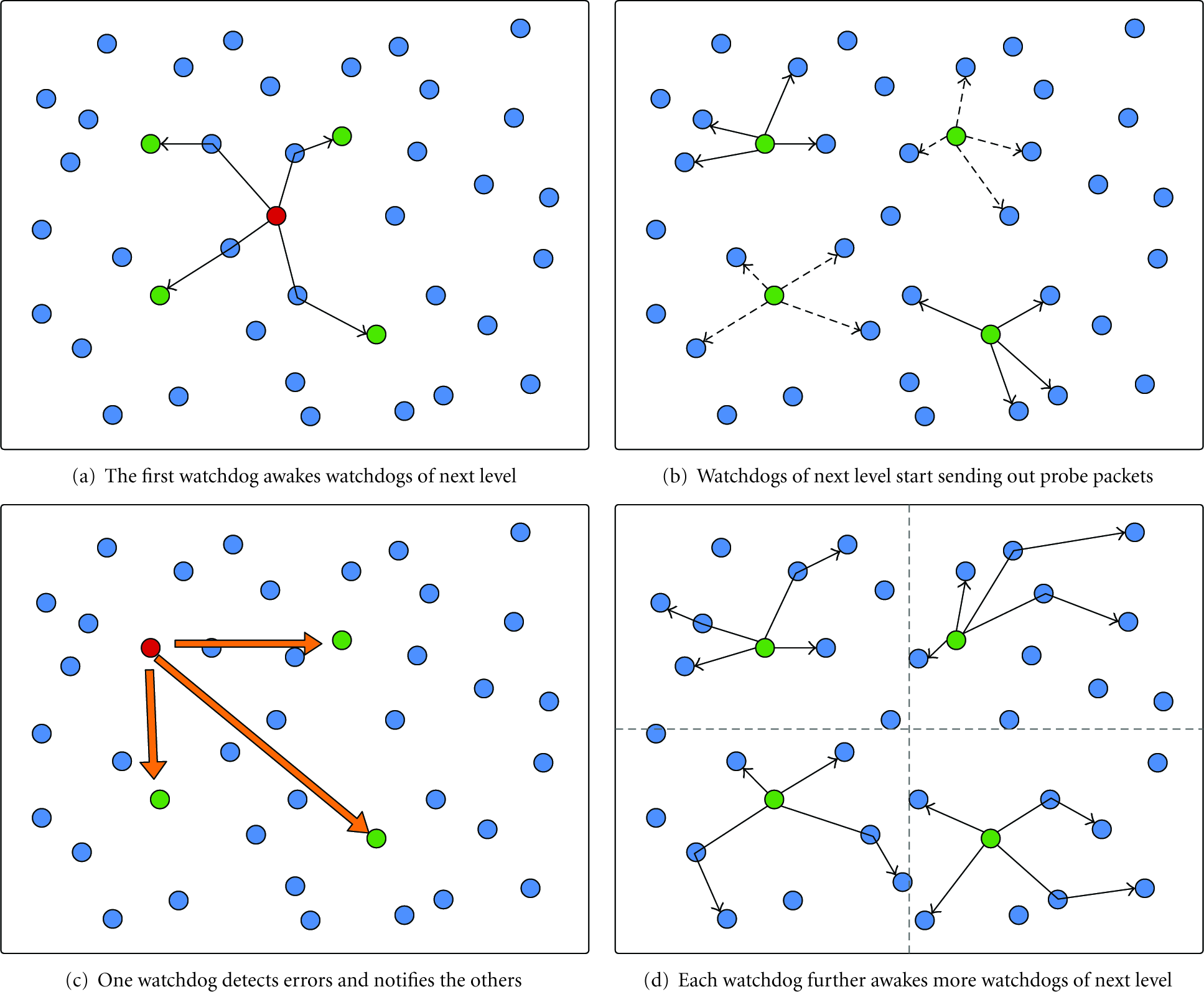
Hierarchical division of the monitoring areas.
4. Analysis and Simulation Result
4.1. Probe Packets and Time Stamp
In most scenarios of RLNC application, the destinations do the decoding as long as they receive full rank of packets. In our algorithm, we modify this scheme by saying that destinations do not decode to fit our requirements. Considering the worst case, to detect an adversary node is that all watchdogs gather around the center of the monitoring area and the adversary node is located at the very edge. Based on the flooding method, the least time slot required for watchdogs to receive modified packets is the hop number of the shortest path from the adversary nodes to the watchdogs, which is half diagonal of the monitoring area. Since the source of modified packets also come from watchdogs, the average number of hop for a modified packet to arrive the watchdogs is
4.2. Range of Shifting
Simply repeating the algorithm will not perform better since the sub-areas are equally divided. If the algorithm starts with the same monitoring area, it will eventually lead to the same result and be in vain. Thus we shift the starting monitoring area in order to minimize the number of innocent nodes. Now the question is how many we should shift each time. It is straightforward to see that if we shift more than a single least monitoring area, this shift is useless. Hence we know the shift range should be no larger than the length of edge of the least monitoring area.
The purpose that we use shift scheme is to further divide the least monitoring area into smaller areas so that we can eliminate the number of innocent nodes. To this end, we shift in both horizontal and vertical directions to let overlapped areas divide the least monitoring area into four smaller areas. Hence the question has become how to divide these four smaller areas in order to get the least innocent nodes. Basically we have two options here, equal division and nonequal division. In fact, the equal division method will have the least expected value of innocent nodes. The mathematical analysis is in Section 5, and the simulation results also support our idea.
4.3. Innocent Nodes and Overhead
When we mark the nodes in the least monitoring area as suspect nodes, we mark all the nodes in the area. In fact, some nodes are normal nodes but marked as suspects, and we call them innocent nodes. Consider the case in which we only perform identification algorithm once without using suspect table. It is straightforward that uniform distribution of Byzantine nodes can lead to the worst result with the most innocent nodes. The ratio of innocent nodes is upper bounded by
4.4. Simulation Results
In our simulation, we uniformly distribute 400, 600, 800, and 1000 nodes in a square area with width of 800 and node communication range is 50. We simulate our algorithm under the circumstance of the amount of adversary nodes varying from 5 to 45, and these adversaries are uniformly and normally distributed. Figure 4 is the first result of our algorithm, we can see that the innocent ratio of uniform distribution pattern is quite high. The uniform distribution pattern is the worst case to our algorithm. In order to decrease the amount of innocent nodes, we introduce shift scheme. The results are shown in Figure 5. The results with more nodes are in Figure 6. As we can see, our algorithm performs better in a dense topology. Performing shift scheme in our algorithm can eliminate innocent ratio effectively, but it also drags down the catch ratio a little bit, because shift scheme also generates holes around boundaries, which cannot be detected sometimes. The result shows that the catch ratio only drops a little, which is an acceptable value.

Innocent ratio and Byzantine catch ratio for two different distribution pattern of adversaries.

Innocent ratio and Byzantine catch ratio with shift scheme.

Results for more nodes.
5. Analysis
The shift scheme aims to further divide the least monitoring areas into smaller areas so that we can decrease the number of innocent nodes. With it, the final results of marked areas in each run of algorithm will be different. The overlapped marked areas are smaller than the least monitoring areas and contain less innocent nodes. Consider the case that overlapped areas divide a least monitoring area A into four smaller areas,
Claim
The expectation value of number of innocent nodes will reach a minimum when the least monitoring area A is divided into four equal areas.
Proof.
Assume that the area A is of size

We want to have


Now we need to resort to the second-order sufficient conditions to determine if the problem reaches a maximum or minimum at


6. Conclusions and Further Work
We have proposed a locating algorithm in appliance of RLNC to locate compromised Byzantine nodes in a network. Our algorithm can locate the areas where adversary nodes locate with some normal nodes being mistaken as adversary nodes. To reduce the number of mistaken nodes, we use a shift scheme to eliminate the probability of being mistaken. The simulation results show that our algorithm performs well in Guassian distribution pattern for adversary nodes. In the worst case, uniform distribution pattern for adversary nodes, we still can locate most adversary nodes and reduce almost 10% of mistaken ratio by shift scheme. We also give discussion about the best policy for shift scheme. Fixing the shift range to the half length of the least monitoring area has the best performance.
Even though we do locate the areas where adversary nodes lie, but there still exist mistaken nodes. A second stage algorithm is required in order to precisely identify each adversary node. Sampling each node one by one in the most suspicious area or combining some special coding scheme with our algorithm may be a worthy researching direction.