
Abstract
Magnetorheological (MR) damper, a kind of intelligent vibration mitigation device, can be used to reduce the vibration or dynamic responses of structures. Its damping forces can be adjusted in real-time by updating control currents of the MR damper according to the state parameters of the structure. In this paper, a single-chip microprocessor (SCM) for MR damper coupling sensing and control is developed. The SCM has three main functions: the first one is that it can collect the acceleration responses of the structure by using the acceleration sensor in real-time; the second one is that it can use the segmented control strategy to decide the control currents of the MR damper according to the collected acceleration information; the third one is that based on the PWM technology it can realize to accurately supply power for the MR damper. The developed SCM is tested through experiment. The analysis results of the simulation and experiment show that the SCM can collect the state information of the structure in real-time and realize to choose the currents of MR damper accurately to control the damping forces of the MR damper.
1. Instruction
The magnetorheological (MR) fluid belongs to the class of smart materials. The essential characteristic of MR fluids is that it can reversibly change from free-flowing, linear viscous liquids to semisolids having controllable yield strength in milliseconds when exposed to a magnetic field. This feature provides simple, quiet, rapid-response interfaces between electronic controls and mechanical systems [1]. The MR damper utilizing MR fluids to provide controllable damping forces is a kind of intelligent semiactive vibration mitigation device. In 1996, Carlson and Spencer [2] have been designed and built a 20t MR damper to study the salient features of large-scale MR devices. In 2001, the first full-scale implementation of MR dampers in building was realized in the National Museum of Emerging Science and Innovation of Tokyo. In this building, two 30t MR dampers built by the Sanwa Tekki Corporation were installed between the third and fifth floors; the MR fluids inside the damper are manufactured by the Lord Corporation [3]. In 2001, Ni et al. [4] presented a method to identify the characteristics of a MR damper for a cable bridge. In 2003, Fujitani et al. [5] developed a 40t MR damper for a real base-isolated building in Japan. In 2008, Xu and Guo [6] built a 26t MR damper to investigate its mechanical performances. In 2012, Li et al. [7] researched wind-induced vibration control of Dalian international trade mansion by tuned liquid dampers.
MR dampers are controllable devices by adjusting currents of the coils to change the magnetic field intensity to control their damping forces, so these are very important that how to choose the control currents, and then how to apply the control currents to MR dampers. Some control strategies and power supply methods of MR dampers have been developed by researchers. In 1996, Dyke et al. [8] proposed a semiactive clipped optimal control strategy based on acceleration feedback for the MR damper. In 1998, Chung et al. [9] also used the acceleration feedback control of seismic structures to successfully reduce vibration of structures. In 2003, Xu et al. [10] presented a neural networks control method. In 2005, Wang and Liao [11] presented an inverse neural network model for MR dampers to generate the control voltage. In 2006, Xu and Guo [12] developed a fuzzy control method for earthquake mitigation structures with MR dampers. In 2004, Yang et al. [13] developed a current-driver power supply to power a MR damper, and the current-driven power supply can substantially reduce the MR damper response time. In 2004, Lord Corporation and Motorola Incorporation [14] have designed controllers of MR dampers in the automobile field. In 2007, Liu [15] presented a controllable current amplifier for MR damper. In 2011, Yi et al. [16] present a method to place sensors for structure.
If MR dampers will be used to reduce the vibration successfully, except for the current-driver power supply, the information collection system is necessary. That is, the sensing system should be used to monitor state parameters of the structure building to realize the real-time vibration control of the structure. In this paper a single-chip microprocessor (SCM) for MR damper coupling sensing and control is developed to monitor the structure and control MR dampers. The SCM has three main functions: the first one is that it can collect the acceleration responses of the structure by using the acceleration sensor in real-time; the second one is that it can use the segmented control strategy to decide the control currents of the MR damper according to the collected acceleration information; the third one is that based on the PWM technology it can realize to accurately supply power for the MR damper. The developed SCM is tested through experiment. The analysis results of the simulation and experiment show that the SCM can collect the state information of the structure in real-time and realize to choose the currents of MR damper accurately to control the damping forces of the MR damper.
2. Mathematical Model of MR Dampers
MR dampers typically consist of a hydraulic cylinder containing micrometer-sized magnetically polarizable particles dispersed in hydrocarbon oil, as shown in Figure 1. The Bingham model [12] is often used to one of the mathematical model of MR dampers, and its relationship between the stress and strain rate can be expressed as


Schematic of MR damper.
3. Design of SCM for MR Damper Coupling Sensing and Control
A SCM for MR dampers coupling sensing and control, monitoring the structure and controlling MR dampers, is developed. Its design block diagram is shown in Figure 2. As shown in Figure 2, the SCM has three main functions: the first one is that it can collect the acceleration responses of the structure by using the acceleration sensor in real-time; the second one is that it can use the segmented control strategy to decide the control currents of the MR damper according to the collected acceleration information by using SCM; the third one is that based on the PWM technology it can realize to accurately supply power for the MR damper.

The block design diagram of the SCM for MR dampers coupling sensing and control.
3.1. Design of Sensing System
In the process of the vibration mitigation control of structures with MR dampers, structural acceleration is one of important parameters will clearly show the vibration condition of the structure, and it is also very useful to decide control currents of MR dampers. This paper will use a three axis low-g acceleration sensor (MMA7260QT [17]) to collect acceleration responses of the structure in real-time. The MMA7260QT low cost capacitive micromachined accelerometer features signal conditioning, a 1-pole low pass filter, temperature compensation, and g-Select which allows for the selection among 4 sensitivities. Zero-g offset full scale span and filter cut-off are factory set and require no external devices. It includes a sleep mode that makes it ideal for handheld battery powered electronics. The device can measure both + and − acceleration, and transform acceleration to voltage signal. With no input acceleration, the output is at mid-supply. For positive acceleration, the output will increase above


The connection diagram of MMA7260QT.
3.2. Design of Control Strategy
In order to effectively reduce the vibration responses of the structure with MR dampers under earthquake or wind excitation, the control currents must be adjusted in real-time according to the structural state parameters collected by sensors. This paper uses a microcontroller, Atmega16, to receive the voltage output signal of the acceleration sensor, produce the control signal of the MR damper's current by using the segmented control strategy, and then output control current signal to the MR damper by using PWM technology.
The segmented control strategy is an easy method to be realized. It can be described as

The microcontroller cannot output the control current of the MR damper, so pulse-width modulation (PWM) technique is used. PWM [18] is a powerful technique for controlling analog circuits with a processor's digital outputs. PWM is employed in a wide variety of applications, ranging from measurement and communications to power control and conversion. As we all know, at any moment, the output of the digital circuit only has two states, ON and OFF. On the other hand, an analog signal has a continuously varying value, with infinite resolution in both time and magnitude. PWM is a way of digitally encoding analog signal levels. Through the use of high-resolution counters, the duty cycle of a square wave is modulated to encode a specific analog signal level. The PWM signal is still digital because, at any given instant of time, the full DC supply is either fully on or fully off. The voltage or current source is supplied to the analog load by means of a repeating series of ON and OFF pulses. The ON-time is the time during which the DC supply is applied to the load, and the OFF-time is the period during which the supply is switched off. Given a sufficient bandwidth, any analog value can be encoded with PWM. At the same time, one of the advantages of PWM is that the signal remains digital all the way from the processor to the controlled system; no digital-to-analog conversion is necessary. By keeping the digital signal, noise effects are minimized.
The microcontroller, Atmega16 [19], produced by Atmel Corporation, can output PWM control signal to the MR damper. Figure 4 is the Atmega16's connection diagram. It can be seen from Figures 3 and 4 that: (1) the Atmega16's PB0 and PB1 pins are connected with the MMA7260QT's g-select1 and g-select2 pins, respectively, to setup the sensor's working rage as

The connection diagram of Atmegal16.
4. Experiment of SCM for MR Damper Coupling Sensing and Control
According to the above principle, the SCM for MR damper coupling sensing and control is developed, as shown in Figure 5. In order to grasp and analysis the performance of the SCM, a series of experiments are carried out, including static experiment and dynamic experiment, as shown in Figure 6.
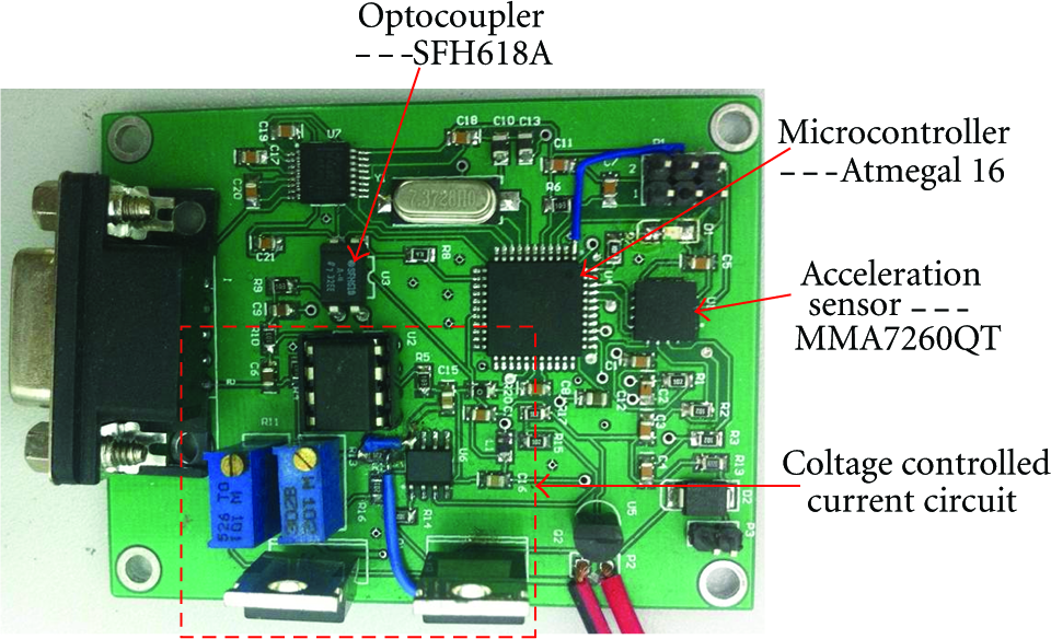
The SCM for MR dampers coupling sensing and control.

The performance experiment of SCM (a) the static experiment of SCM and (b) the dynamic experiment of SCM.
In the process of the static experiment of the SCM, the SCM is connected with the MR damper, and it will be motionless. Because the SCM is motionless, the acceleration and the PWM waveform by produced by the microcontroller will be not change. It can be seen from Figure 6(a) that the direction of the z-axis of the acceleration sensor is the direction of the Earth's gravity field, so the three axis outputs of the acceleration are

During the dynamic experiment of the SCM, the SCM is fastened the top of the vibration machine, and it will vibrate under the different sine wave excitation. Figure 6(b) shows the PWM waveforms and values of the magnetic field intensity produced by the MR damper under the same sine wave excitation and at the different moment. At the same time, the currents of the MR damper are measured under the different acceleration, and compared with the expected values, as shown in Table 1 and Figure 7. It can be seen from Table 1 and Figure 7 that the measured values of the currents and the expected values are consistent, and the maximum relative error, 4.17%, meets the requirement of the vibration mitigation of the structure.
Acceleration comparison of excepted value and measured value.


The comparison cure of measured value and excepted value.
5. Conclusions
In this paper, a single-chip microprocessor (SCM) for MR damper coupling sensing and control is developed to monitor the structure and control MR dampers. It has three main functions: the first one is that it can collect the acceleration responses of the structure by using the acceleration sensor in real-time; the second one is that it can use the segmented control strategy to decide the control currents of the MR damper according to the collected acceleration information; the third one is that based on the PWM technology it can realize to accurately supply power for the MR damper. The developed SCM is tested by simulation and experiment. The following conclusions are obtained from this study.
The MMA7260QT is a three-axis low-g acceleration sensor. It integrates a low pass filter and can realize accurately measure the acceleration responses of the structure. Furthermore, it is easy to connect with the microcontroller and send the acceleration information to the microcontroller by voltage signals.
The static and dynamic experiments of the SCM indicate that the SCM can use the segmented control strategy to produce the accurate PWM signal according to the collected acceleration data. And the measured values of the currents and the expected values are consistent.
Footnotes
Acknowledgments
This work was financially supported by the National Natural Science Foundation of China (61004064), NSAF of China (11176008), Jiangsu Province Brace Program (BE2010069), Jiangsu Province Postgraduate Research, and Innovation Project of the Universities in (CXZZ_0160).