
Abstract
We discuss the proof of concept that gives mobile robotic units the ability to provide a mobile wireless mesh network providing wireless service to end-clients and also demonstrate the ability to increase the throughput of this mobile wireless mesh system by autonomously reducing the hop count required for network traffic to transit through. In doing so, this proof-of-concept contributes to future development of a robust system which can be deployed and utilized in different situations and industry.
1. Introduction
In the 21st century, WIFI and wireless hotspots are familiar services provided to consumers—specifically referring to the 802.11a/b/g/n IEEE standard. In many nations, consumers access data and web content using mobile devices such as tablets, phones, and laptops via WIFI. It has integrated so effectively into our lives and social fabric that we easily take it for granted. What would we do without broadband wireless?
The motivation of the paper is to demonstrate the ability of using mobile robotic units to establish a mobile mesh network. The concept of mobile networks using robotics is nothing of a novel idea as our research group already introduced in [1, 2]; however, the use of robots to form a wireless mesh broadband network is a novel idea and approach to providing broadband wireless service almost anywhere in the world and in any situation. We believe robotics autonomously forming self-healing broadband wireless networks will be the future of wireless services and data communication. Realisticlly, we look to apply this technology first to search-and-rescue situations. However, we introduce this concept with the intent for it to be applicable to many different industries and situations.
The purpose of this paper is to demonstrate a proof-of-concept robotic system that utilizes wireless mesh technology to form autonomous wireless broadband networks. Furthermore, the system will also demonstrate the ability to increase the throughput of the existing system by redistributing the nodes of the existing network given that a precondition is met. Through this proof-of-concept, we hope to show the potential of future networks to be self-forming, adaptable, and self-healing whenever node failures exist in the network. We further emphasize that the use of mesh technology is a differentiating factor from other existing systems with a similar purpose.
In this paper, we will discuss related works and how our system and concept differ from other systems. We further explain and demonstrate how it is more scalable and adaptable. We reference our previous work regarding radio frequency (RF) signal sensing and the use of relative signal strength indicator (RSSI) [3] to control the actions of our robotic units. Thereafter, we apply this basic concept to multiple robotic units and test the system in an open outdoor environment. We will describe the layout and results of our simulation and experiment. Additionally, we will explain the algorithm of our system, demonstrating the proof of concept of which we hope future research could use as a basis to build upon. Finally, we will discuss the assumptions and limitations that enable this system and concept to work and the future work that is required.
2. Background
Conventional mesh technology is known to be extensible, resilient, self-healing, and provide coverage in hard-to-wire areas [4, 5]. Conventional wireless implementations rely on a wired wireless distribution system (WDS) to communicate between APs for roaming and management; this communication link is known as the backhaul [6]. Mesh technology eliminates the need of a wired WDS. This enables mesh technology to be rapidly deployed with a lower-cost backhaul and allows more flexibility in the configuration of the network based on demand. Additionally, another benefit of wireless mesh technology is the high data rate of 54 Mbps [7]. With these benefits of wireless mesh access point (AP) compared to conventional wireless AP implementation and configuration, wireless mesh APs were used in our system to establish an autonomous wireless broadband networks [8].
We understand the importance of wireless communication; we utilize its services every time we check our email at the airport or coffee shop on our laptops, whenever we turn our phones to WIFI mode when we enter a building to check the news or the weather. Without a doubt, WIFI services are important. The degree of importance of communication and wireless communication is further elevated during instances of natural disasters. According to a World Health Organization (WHO) report after the earthquake of Haiti:
Information may be the most important commodity during emergencies. Information may also be the most rapid public health response ahead of the delivery of aid. In addition, the dissemination of information in a timely and transparent manner also helps generate trust and credibility in response activities and agencies providing relief [9].
During severe natural disasters, like the earthquake of Haiti [10] or the tsunami that hit Japan in 2011 [11], communication infrastructures are either obliterated or so severely damaged that they are rendered inoperable. Hence, rescue teams and responders resort to two-way radios [12] or flying in circles broadcasting emergency messages to victims [13].
Our system or proof-of-concept's design goal is to provide broadband wireless communication. We find that if we can prove the ability to establish a mobile wireless mesh network, we can provide a basis for which this concept can be integrated onto different robotic platforms to be implemented during severe natural disasters. Because mesh network technology is known to be resilient, self-healing, and scalable, we find these qualities appropriate to address the need to fulfill a communication gap during severe natural disasters. Additionally, the ability of a mobile platform is desirable to accommodate for topographical challenges and operational movement of personnel.
There are similar systems and research ongoing with the same purpose and goal as our system; however, none have implemented mesh technology; hence, they do not benefit from the attributes of a mesh network. The US Navy uses robots to deploy network “relay bricks” to extend a single communication link to a robot from a far distance, allowing the operator to control the unit from many miles away [14]. The limitations of this approach are the ability to communicate with one end-device and the immovable nature of the “relay bricks.” If the bricks were laid out in a northward direction, but later in the operation, the robot on the far end needed to move west, east, or south, the system would not be able to accommodate due to the immovable bricks.
In London, researchers use mobile robots equipped with ad hoc radios to help officials coordinate search and rescue operations. The use of ad hoc radios, however, limits the system from establishing communication with other nodes through a third-party node; all communication established must be peer to peer using ad hoc radios [15]. Another system known as Autonomous Wireless Aerial Vehicles (AWARE) uses aerial vehicles and personnel to establish a communication medium for emergency personnel. The system relies on aerial vehicles to place static wireless sensors in different locations to provide communication coverage for personnel. The system's static placement of wireless nodes does not scale well to changing environments and conditions or operational needs [16].
Our research concept began using small robotic units, iRobot Create [17], integrated with mesh AP, Proxim-4000 [18]; we successfully demonstrated the ability to have robots perform specified actions based on the RF signal received. We further demonstrated that based on simple RF sensing, our robotic unit was able to complete and optimize a communication link of which two stationary APs were initially placed at a distance and initially unreachable [1]. From this basic concept, we derived a more robust system, of which outdoor robots, P3-AT [19], were equipped with mesh APs with the goal to establish autonomously a linear wireless broadband mesh network [20].
The motivation for this paper is to demonstrate that it is possible to establish a mobile broadband wireless network using mobile robots and wireless mesh technology. The proof-of-concept is evaluated through a two-stage experiment of which the first stage, a wireless mesh network, is established in a linear topology. In the second stage of the experiment, we demonstrate the ability for a robot to redistribute autonomously the network to reduce the hop count network traffic transit, which results in an increase in throughput. The increase in throughput allows for more devices and units to exist on the network and to communicate and transmit data in a timely manner.
3. Concept of RF Signal Sensing
In our previous work, we experimented with the basic concept of RF signal sensing, and based on the RSSI the robotic unit performed a certain action. We denote the RSSI which a robotic unit responds to as the RSSI Threshold. Figure 1 demonstrates the robotic unit's ability to stop when it detects an RSSI level greater than 53. This condition could have been applied to any RSSI level, but the condition

Basic RF sensing using iRobot Create and simple-reflex agent model [1].
Based on this simple concept of RF sensing and utilizing simple-reflex agent model, we further applied it to our proof-of-concept using mesh technology with more robust robotic units.
4. Algorithm
The algorithm of this proof-of-concept consists of two stages: linear expansion (LE) and the backbone infrastructure route optimization (BIRO). Essentially, not only is it the experiment demonstrating that robotic units can autonomously create a mobile broadband mesh network but also it is capable of increasing the throughput of the network by autonomously reducing the hop count that network traffic requires to transit through. The basic concept of using multiple robots in the proposed application is shown in Figure 2.

A configuration of self-configurable wireless networks using multiple mobile robots carrying antennas.
As depicted in Figure 2, the use of multiple mobile robots carrying APs will allow a wireless signal to be relayed from the server to the client. Each robot carries one AP with an internal antenna to form a linear network for long distance coverage. Also, additional antennas and radios can be added to create additional multipoint connections. The number of robots is determined by the requirements of the system, that is,

where
In the first stage of the algorithm, LE, the purpose is to establish a wireless mesh link using multiple mobile mesh APs and a root AP. Additionally, the purpose of the LE stage is to stretch the coverage of the mobile network as far as possible without losing the established connection with the previous node.
LE stage begins with all multiple mobile units associated to the root node, which remains stationary and positioned in a straight convoy formation, as depicted in Figure 3(a). Each unit is assigned a role based on its position in the convoy. The first node is designated as L (leader). The nodes from the second unit to the unit preceding the last in line are designated as

Visual description of LE algorithm: (a) initial state (b) for leader, L (c) for followers,
The algorithm is set up so that the robots are always sensing RF signal to determine their action. In this algorithm, each robot is responsible for sensing the RF of the robot preceding it, and the tail node robot is responsible for sensing the RF of the stationary root or gateway meshed enabled AP. With this algorithm, if the “root” AP is to move closer to the T node unit, then the entire system will move forward to account for the change in RSSI Threshold in effect, it would create a ripple effect that is reflected throughout the system.
Each robotic unit looks up their assigned priority and the assigned RSSI threshold limit, and sonar range limit. If robot is assigned “L,” the robot will drive straight until the RSSI connection with “
/* /* Search for RSSI of AP “ Stop driving; Drive straight;
If robot is assigned priority “
/* Stage 1. /* Stop driving; Search for RSSI of AP “ Stop driving; Drive straight;
If robot is assigned T, object detection capabilities have been enabled as well, and the robot will drive straight until the RSSI connection with root1,
/* /* Stop driving; Search for RSSI of AP root 1 “ Stop driving; Drive straight;

LE Algorithm formalized.
It is important to mention that the root or gateway mesh AP, denoted as
In the BIRO algorithm, the robotic unit is designated as
/*
View topology tree; Stop driving; Drive straight;
5. Simulation
To validate our approach, especially for the LE algorithm, we have built a simulation environment in Simulink of Matlab. We have then run the program in a second time scale to obtain the simulation results that would be the same as those from the real world. Figure 5 represents the entire simulation environment, mainly composed of mobile robots motion block and main block with the LE algorithm (original simulation blocks were from [21] and slightly modified for this research). We have then established several assumptions as follows.
Slew rates of the mobile robots’ velocity are instant; that is, acceleration and deceleration of the robot's motion are ignored.
RSSI values for RF signal sensing are proportional to the distance between neighboring two nodes.
All robots are located in a same point at the initial simulation run.

LE Algorithm test environment built in Simulink.
The second assumption may differ from the real world application, because the RSSI values are not often proportional to the distance between the two nodes due to the ever-changing RSSI patterns [2]. However, in the Friis transmission formular (2), if we assume antenna gains

where
For simulation, we have used a simple model of the mobile robot having a motion equation as [21]

where x, y, θ, V are the robot's x position, y position, heading angle, velocity in the world frame. L is a length between two wheels, and γ is the angle of the steered wheel. Note that the position of the robot having this motion equation is controlled by the robot's velocity manipulation in general. We have used five mobile robots (
Figure 6 shows the linear formation was generated over about 110 seconds of the simulation time. In Figure 6, time transitions during the simulation are depicted on top right figures. At the beginning of simulation, all robots and the root node were located in the origin. Then, the first mobile robot, denoted as L, started moving forward. This robot kept moving until the stop condition was activated at 105 sec (look at the top graph in Figure 8). The second mobile robot then, denoted as

Linear formation results using LE Algorithm.
After the complete of the first linear formation (around 110 sec), we have investigated the effect to the entire system when the root AP moves closer to the T node unit. In this simulation (from 120 sec to 200 sec), we have intentionally moved the root AP to 15 meters to the right direction from the beginning of simulation (120 sec) so that it could be closer to the tail node T. The results of this additional simulation are depicted in Figure 7. As shown in Figures 7 and 8 around at 120 sec, as soon as root was closer to the T, the distance-based condition of the most left node was deactivated, and then the T resumed moving forward. The movement of the T resulted in having

Effects of relocating of root node.

Mobile robots’ velocities from the LE simulation.
6. Experiment Setup
Before the experiment could be executed, 4 mobile P3-AT (three are for the LE, and one is for the BIRO, so the number of nodes and robots in the algorithm becomes
On the left of the tail node T, a P3-AT equipped with a Proxim-4000 is set to Mesh Portal mode and remains until the first stage of the experiment is completed. Two laptops are equipped with Iperf [22]; one is set as the server, and the other is set as the client. Additionally, crossover Ethernet cables are used to ensure that the laptops are associated to their assigned units and do not associate wirelessly to other units; this ensures validity in the experiment.
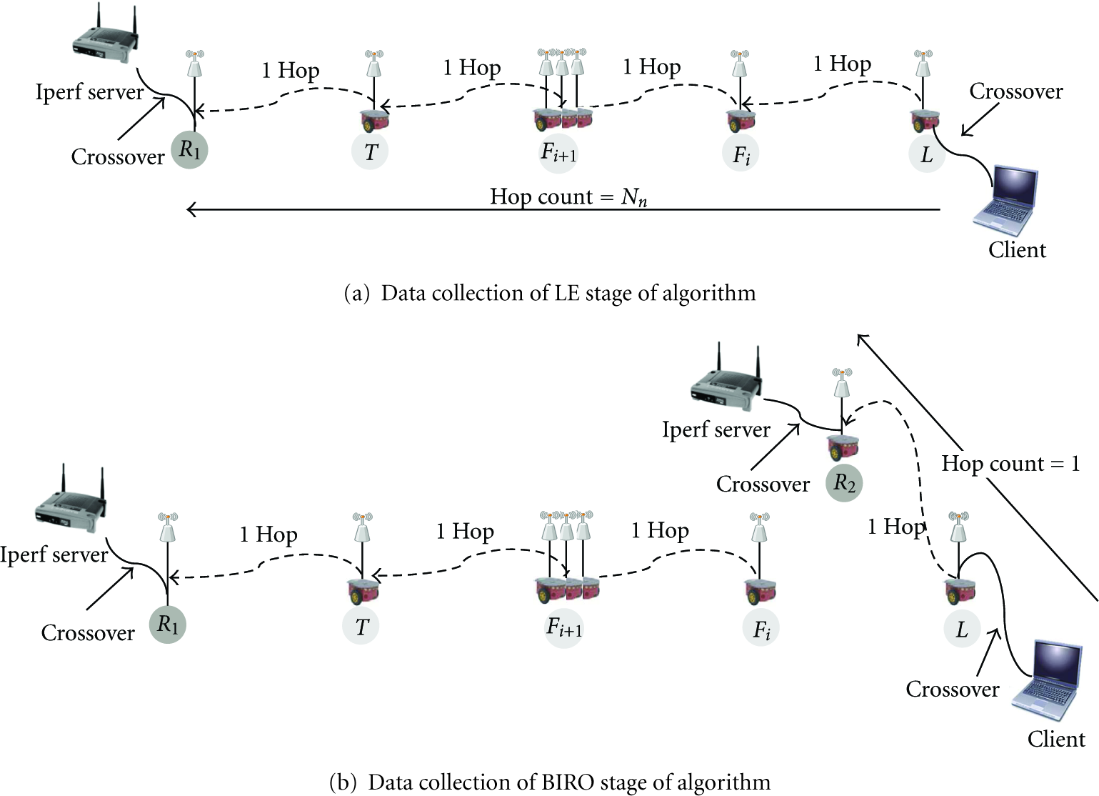
The experiment is executed in two stages: LE and BIRO. Procedures for the first stage of the experiment, LE, are depicted in Figure 9(a) and as follows.
Initiate and start all robotic units, execute LE algorithm.
Wait for all units to stabilize (stop) for good.
Start Iperf server connected via crossover to
Connect Iperf client connected via crossover to L.
Collect throughput measurement three times, each measurement collected in 10 seconds interval.
Stage transition from LE to BIRO.
After the completion of the LE stage, the BIRO stage executes as depicted in Figure 9(b) and as follows.
Wait for
Start Iperf server connected via crossover to
Connect Iperf client connected via crossover to
Collect throughput measurement three times, each measurement collected in 10 seconds interval.
The entire 2-staged experiment was repeated 10 times. Over 300 data points were collected as a result. Additionally, the RSSI Threshold set for this experiment was 30.
7. Results and Analysis
The results of the experiment were a linear formation of robotic units connected via wireless mesh APs using internal antennae. The backhaul was using 802.11a, and 802.11g was used to provide wireless data service to end-users and end-devices. Figure 10 shows the robots in formation and ready for deployment, and Figure 11 shows the three robotic units stretched over a football field.

Initial state of system, robots in a convoy formation.

Outdoor field experiment of LE stage of experiment.
Figure 12 shows the three nodes stretched over a distance up to 70 meters. This figure proves that a short communication link with one node could be extended to a far distance using multiple robots in a linear link. Also, it proves that the BIRO node successfully detected the end node “L” and stopped around it.

Distances from outdoor field experiment of LE stage and BIRO stage.
In the LE stage of the experiment, when all three mobile units were stretched out in a linear formation, the

Network Topology.
Following the completion of the LE stage, the BIRO stage was executed. Upon the completion of the BIRO stage, the following network topology was established as shown in Figure 13(b). As shown in Figure 13(b), root AP
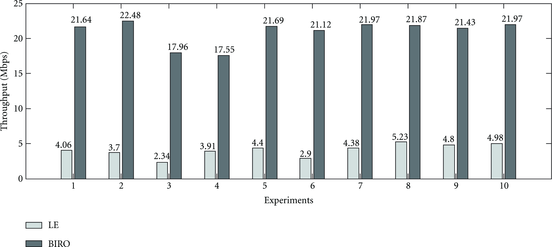
From the collection of network throughput from 10 experimental runs, Figure 14 shows the throughput performance of the experiment for the LE and BIRO stage of the experiment. From the chart in Figure 14, it is observed that by reducing the hop count during the BIRO stage of the experiment, the throughput was significantly greater than the throughput performance during the LE stage of the experiment. During the LE stage, network traffic transits through 3 hops, compared to 1 hop during the BIRO stage. The chart also shows the numerical data of the throughput collected for each experimental run. During each experiment of each stage, the collection of throughput data was measured 3 times for 10 seconds. The average was calculated from the 3 measurement instances taken from each experiment of each stage.
Network throughput performance over 10 experimental runs.
As a result, Figure 14 shows that robotic units have the ability to optimize a mobile wireless mesh network by reducing the amount of hop counts a network much traverses. Finally, this experiment shows that it is not only possible to establish a mobile wireless mesh network but it is also possible to improve the existing mobile wireless mesh network with additional robotic units equipped with gateway AP that have the ability to redistribute the wireless mesh network.
8. Assumption and Limitations
The success of the experiment and the future applicability of this research concept run under the assumption that the root APs,
Additionally, the three mobile AP units were limited to the use of internal antennae, and the units were only mounted 0.5 meter above the ground. This low-level mount of the AP significantly reduces the distance covered by each mobile AP unit and the performance of the overall system. Additionally, the units were limited to a small power source lasting only 4 hours.
9. Future Work and Conclusion
Future work will include the implementation of a system that utilizes external antennae, both omnidirectional and directional. Additionally, a new mounting system will be designed to increase the height of the antennae to increase coverage and network performance for the system.
With the given experiment, we have successfully proved the proof-of-concept of establishing mobile broadband mesh networks using mobile robots. Additionally, we have shown that we can further improve network performance by reducing the hop count of the network traffic from the furthest network node, all of this operation done robotically and autonomously. If
We hope that through the use of the simple concept of RF sensing, the concept of mobile broadband mesh network can be further developed and matured to be implemented on different robotic platforms paving way to a new era of wireless communication and services by providing wireless communication almost anywhere and at anytime in the world.